US10361374B2 - Amine compound and organic light emitting device including the same - Google Patents
Amine compound and organic light emitting device including the same Download PDFInfo
- Publication number
- US10361374B2 US10361374B2 US15/199,764 US201615199764A US10361374B2 US 10361374 B2 US10361374 B2 US 10361374B2 US 201615199764 A US201615199764 A US 201615199764A US 10361374 B2 US10361374 B2 US 10361374B2
- Authority
- US
- United States
- Prior art keywords
- group
- formula
- substituted
- carbon atoms
- unsubstituted
- Prior art date
- Legal status (The legal status is an assumption and is not a legal conclusion. Google has not performed a legal analysis and makes no representation as to the accuracy of the status listed.)
- Active
Links
- 0 *C(*)(*)C.*C(*)=C(*)C.*C(*)=O.*N(*)*.*N=C(*)*.*O*.*P(*)(*)=O.*S(*)(=O)=O.*S(*)=O.*S*.*[Si](*)(*)C Chemical compound *C(*)(*)C.*C(*)=C(*)C.*C(*)=O.*N(*)*.*N=C(*)*.*O*.*P(*)(*)=O.*S(*)(=O)=O.*S(*)=O.*S*.*[Si](*)(*)C 0.000 description 30
- KUIVQPYPRSKMMM-UHFFFAOYSA-N C1=CC=C(C2(C3=CC=C(C4=CC=C(N(C5=C6C=CC=CC6=CC=C5)C5=C6C=CC=CC6=CC=C5)C=C4)C=C3)C3=CC=CC4=C3C3=C2C=CC=C3/C=C\4)C=C1.C1=CC=C(C2(C3=CC=C(C4=CC=C(N(C5=CC=C(C6=CC=CC7=C6C=CC=C7)C=C5)C5=C6C=CC=CC6=CC=C5)C=C4)C=C3)C3=CC=CC4=C3C3=C2C=CC=C3/C=C\4)C=C1.C1=CC=C(C2(C3=CC=C(C4=CC=C(N(C5=CC=C(C6=CC=CC7=C6C=CC=C7)C=C5)C5=CC=C(C6=C7C=CC=CC7=CC=C6)C=C5)C=C4)C=C3)C3=CC=CC4=C3C3=C2C=CC=C3/C=C\4)C=C1.C1=CC=C(C2=CC=C(N(C3=CC=C(C4=CC=C(C5(C6=CC=CC=C6)C6=CC=CC7=C6C6=C5C=CC=C6/C=C\7)C=C4)C=C3)C3=CC=C(C4=CC=CC5=C4C=CC=C5)C=C3)C=C2)C=C1 Chemical compound C1=CC=C(C2(C3=CC=C(C4=CC=C(N(C5=C6C=CC=CC6=CC=C5)C5=C6C=CC=CC6=CC=C5)C=C4)C=C3)C3=CC=CC4=C3C3=C2C=CC=C3/C=C\4)C=C1.C1=CC=C(C2(C3=CC=C(C4=CC=C(N(C5=CC=C(C6=CC=CC7=C6C=CC=C7)C=C5)C5=C6C=CC=CC6=CC=C5)C=C4)C=C3)C3=CC=CC4=C3C3=C2C=CC=C3/C=C\4)C=C1.C1=CC=C(C2(C3=CC=C(C4=CC=C(N(C5=CC=C(C6=CC=CC7=C6C=CC=C7)C=C5)C5=CC=C(C6=C7C=CC=CC7=CC=C6)C=C5)C=C4)C=C3)C3=CC=CC4=C3C3=C2C=CC=C3/C=C\4)C=C1.C1=CC=C(C2=CC=C(N(C3=CC=C(C4=CC=C(C5(C6=CC=CC=C6)C6=CC=CC7=C6C6=C5C=CC=C6/C=C\7)C=C4)C=C3)C3=CC=C(C4=CC=CC5=C4C=CC=C5)C=C3)C=C2)C=C1 KUIVQPYPRSKMMM-UHFFFAOYSA-N 0.000 description 6
- JQTWZTOMUZLYCO-UHFFFAOYSA-N C1=CC=C(C2(C3=CC=C(N(C4=C5C=CC=CC5=CC=C4)C4=C5C=CC=CC5=CC=C4)C=C3)C3=CC=CC4=C3C3=C2C=CC=C3/C=C\4)C=C1.C1=CC=C(C2(C3=CC=C(N(C4=CC=C(C5=CC=CC6=C5C=CC=C6)C=C4)C4=C5C=CC=CC5=CC=C4)C=C3)C3=CC=CC4=C3C3=C2C=CC=C3/C=C\4)C=C1.C1=CC=C(C2(C3=CC=C(N(C4=CC=C(C5=CC=CC6=C5C=CC=C6)C=C4)C4=CC=C(C5=C6C=CC=CC6=CC=C5)C=C4)C=C3)C3=CC=CC4=C3C3=C2C=CC=C3/C=C\4)C=C1.C1=CC=C(C2=CC=C(N(C3=CC=C(C4=CC=CC5=C4C=CC=C5)C=C3)C3=CC=C(C4(C5=CC=CC=C5)C5=CC=CC6=C5C5=C4C=CC=C5/C=C\6)C=C3)C=C2)C=C1 Chemical compound C1=CC=C(C2(C3=CC=C(N(C4=C5C=CC=CC5=CC=C4)C4=C5C=CC=CC5=CC=C4)C=C3)C3=CC=CC4=C3C3=C2C=CC=C3/C=C\4)C=C1.C1=CC=C(C2(C3=CC=C(N(C4=CC=C(C5=CC=CC6=C5C=CC=C6)C=C4)C4=C5C=CC=CC5=CC=C4)C=C3)C3=CC=CC4=C3C3=C2C=CC=C3/C=C\4)C=C1.C1=CC=C(C2(C3=CC=C(N(C4=CC=C(C5=CC=CC6=C5C=CC=C6)C=C4)C4=CC=C(C5=C6C=CC=CC6=CC=C5)C=C4)C=C3)C3=CC=CC4=C3C3=C2C=CC=C3/C=C\4)C=C1.C1=CC=C(C2=CC=C(N(C3=CC=C(C4=CC=CC5=C4C=CC=C5)C=C3)C3=CC=C(C4(C5=CC=CC=C5)C5=CC=CC6=C5C5=C4C=CC=C5/C=C\6)C=C3)C=C2)C=C1 JQTWZTOMUZLYCO-UHFFFAOYSA-N 0.000 description 6
- CVRDNLCTNQFDCD-UHFFFAOYSA-N C1=CC=C(C2(C3=CC=C(N(C4=CC=C5C(=C4)OC4=C5C=CC=C4)C4=C5C=CC=CC5=CC=C4)C=C3)C3=CC=CC4=C3C3=C2C=CC=C3O4)C=C1.C1=CC=C(C2(C3=CC=C(N(C4=CC=C5C(=C4)SC4=C5C=CC=C4)C4=C5C=CC=CC5=CC=C4)C=C3)C3=CC=CC4=C3C3=C2C=CC=C3O4)C=C1.C1=CC=C(C2=CC=C(N(C3=CC=CC=C3)C3=CC=C(C4=CC(C5(C6=CC=CC=C6)C6=CC=CC7=C6C6=C5/C=C\C=C\6C=C7)=CC=C4)C=C3)C=C2)C=C1.C1=CC=C(N(C2=CC=CC=C2)C2=CC=C(C3=CC(C4(C5=CC=CC=C5)C5=CC=CC6=C5C5=C4/C=C\C=C\5C=C6)=CC=C3)C=C2)C=C1.CC1(C)C2=CC(N(C3=CC=C(C4(C5=CC=CC=C5)C5=CC=CC6=C5C5=C4C=CC=C5O6)C=C3)C3=C4C=CC=CC4=CC=C3)=CC=C2C2=C1C=CC=C2 Chemical compound C1=CC=C(C2(C3=CC=C(N(C4=CC=C5C(=C4)OC4=C5C=CC=C4)C4=C5C=CC=CC5=CC=C4)C=C3)C3=CC=CC4=C3C3=C2C=CC=C3O4)C=C1.C1=CC=C(C2(C3=CC=C(N(C4=CC=C5C(=C4)SC4=C5C=CC=C4)C4=C5C=CC=CC5=CC=C4)C=C3)C3=CC=CC4=C3C3=C2C=CC=C3O4)C=C1.C1=CC=C(C2=CC=C(N(C3=CC=CC=C3)C3=CC=C(C4=CC(C5(C6=CC=CC=C6)C6=CC=CC7=C6C6=C5/C=C\C=C\6C=C7)=CC=C4)C=C3)C=C2)C=C1.C1=CC=C(N(C2=CC=CC=C2)C2=CC=C(C3=CC(C4(C5=CC=CC=C5)C5=CC=CC6=C5C5=C4/C=C\C=C\5C=C6)=CC=C3)C=C2)C=C1.CC1(C)C2=CC(N(C3=CC=C(C4(C5=CC=CC=C5)C5=CC=CC6=C5C5=C4C=CC=C5O6)C=C3)C3=C4C=CC=CC4=CC=C3)=CC=C2C2=C1C=CC=C2 CVRDNLCTNQFDCD-UHFFFAOYSA-N 0.000 description 6
- RPEPGAPMLASJSQ-UHFFFAOYSA-N C1=CC=C(C2(C3=CC=CC(C4=CC=C(N(C5=C6C=CC=CC6=CC=C5)C5=C6C=CC=CC6=CC=C5)C=C4)=C3)C3=CC=CC4=C3C3=C2/C=C\C=C\3C=C4)C=C1.C1=CC=C(C2(C3=CC=CC(C4=CC=C(N(C5=CC=C(C6=CC=CC7=C6C=CC=C7)C=C5)C5=CC=C(C6=C7C=CC=CC7=CC=C6)C=C5)C=C4)=C3)C3=CC=CC4=C3C3=C2/C=C\C=C\3C=C4)C=C1.C1=CC=C(C2=CC=C(N(C3=CC=C(C4=CC(C5(C6=CC=CC=C6)C6=CC=CC7=C6C6=C5/C=C\C=C\6C=C7)=CC=C4)C=C3)C3=CC=C(C4=CC=CC5=C4C=CC=C5)C=C3)C=C2)C=C1.C1=CC=C(C2=CC=C(N(C3=CC=C(C4=CC=CC=C4)C=C3)C3=CC=C(C4=CC(C5(C6=CC=CC=C6)C6=CC=CC7=C6C6=C5/C=C\C=C\6C=C7)=CC=C4)C=C3)C=C2)C=C1 Chemical compound C1=CC=C(C2(C3=CC=CC(C4=CC=C(N(C5=C6C=CC=CC6=CC=C5)C5=C6C=CC=CC6=CC=C5)C=C4)=C3)C3=CC=CC4=C3C3=C2/C=C\C=C\3C=C4)C=C1.C1=CC=C(C2(C3=CC=CC(C4=CC=C(N(C5=CC=C(C6=CC=CC7=C6C=CC=C7)C=C5)C5=CC=C(C6=C7C=CC=CC7=CC=C6)C=C5)C=C4)=C3)C3=CC=CC4=C3C3=C2/C=C\C=C\3C=C4)C=C1.C1=CC=C(C2=CC=C(N(C3=CC=C(C4=CC(C5(C6=CC=CC=C6)C6=CC=CC7=C6C6=C5/C=C\C=C\6C=C7)=CC=C4)C=C3)C3=CC=C(C4=CC=CC5=C4C=CC=C5)C=C3)C=C2)C=C1.C1=CC=C(C2=CC=C(N(C3=CC=C(C4=CC=CC=C4)C=C3)C3=CC=C(C4=CC(C5(C6=CC=CC=C6)C6=CC=CC7=C6C6=C5/C=C\C=C\6C=C7)=CC=C4)C=C3)C=C2)C=C1 RPEPGAPMLASJSQ-UHFFFAOYSA-N 0.000 description 6
- CBSJLXWVUDBVMI-UHFFFAOYSA-N C1=CC=C(C2(C3=CC=CC(C4=CC=C(N(C5=CC=C(C6=C7C=CC=CC7=CC=C6)C=C5)C5=CC=C6C(=C5)OC5=C6C=CC=C5)C=C4)=C3)C3=CC=CC4=C3C3=C2/C=C\C=C\3C=C4)C=C1.C1=CC=C(C2(C3=CC=CC(C4=CC=C(N(C5=CC=C6C(=C5)OC5=C6C=CC=C5)C5=C6C=CC=CC6=CC=C5)C=C4)=C3)C3=CC=CC4=C3C3=C2/C=C\C=C\3C=C4)C=C1.C1=CC=C(C2(C3=CC=CC(C4=CC=C(N(C5=CC=C6C(=C5)SC5=C6C=CC=C5)C5=C6C=CC=CC6=CC=C5)C=C4)=C3)C3=CC=CC4=C3C3=C2/C=C\C=C\3C=C4)C=C1.C1=CC=C(N(C2=CC=C(C3(C4=CC=CC=C4)C4=CC=CC5=C4C4=C3C=CC=C4/C=C\5)C=C2)C2=CC=C3C(=C2)OC2=C3C=CC=C2)C=C1.CC1(C)C2=CC(N(C3=CC=C(C4=CC(C5(C6=CC=CC=C6)C6=CC=CC7=C6C6=C5/C=C\C=C\6C=C7)=CC=C4)C=C3)C3=C4C=CC=CC4=CC=C3)=CC=C2C2=C1C=CC=C2 Chemical compound C1=CC=C(C2(C3=CC=CC(C4=CC=C(N(C5=CC=C(C6=C7C=CC=CC7=CC=C6)C=C5)C5=CC=C6C(=C5)OC5=C6C=CC=C5)C=C4)=C3)C3=CC=CC4=C3C3=C2/C=C\C=C\3C=C4)C=C1.C1=CC=C(C2(C3=CC=CC(C4=CC=C(N(C5=CC=C6C(=C5)OC5=C6C=CC=C5)C5=C6C=CC=CC6=CC=C5)C=C4)=C3)C3=CC=CC4=C3C3=C2/C=C\C=C\3C=C4)C=C1.C1=CC=C(C2(C3=CC=CC(C4=CC=C(N(C5=CC=C6C(=C5)SC5=C6C=CC=C5)C5=C6C=CC=CC6=CC=C5)C=C4)=C3)C3=CC=CC4=C3C3=C2/C=C\C=C\3C=C4)C=C1.C1=CC=C(N(C2=CC=C(C3(C4=CC=CC=C4)C4=CC=CC5=C4C4=C3C=CC=C4/C=C\5)C=C2)C2=CC=C3C(=C2)OC2=C3C=CC=C2)C=C1.CC1(C)C2=CC(N(C3=CC=C(C4=CC(C5(C6=CC=CC=C6)C6=CC=CC7=C6C6=C5/C=C\C=C\6C=C7)=CC=C4)C=C3)C3=C4C=CC=CC4=CC=C3)=CC=C2C2=C1C=CC=C2 CBSJLXWVUDBVMI-UHFFFAOYSA-N 0.000 description 6
- QEKXEBQFPKRBIC-UHFFFAOYSA-N C1=CC=C(C2(C3=CC=CC(C4=CC=C(N(C5=CC=C(C6=CC=CC7=C6C=CC=C7)C=C5)C5=C6C=CC=CC6=CC=C5)C=C4)=C3)C3=CC=CC4=C3C3=C2/C=C\C=C\3C=C4)C=C1.C1=CC=C(C2=CC=C(N(C3=CC=C(C4=CC(C5(C6=CC=CC=C6)C6=CC=CC7=C6C6=C5/C=C\C=C\6C=C7)=CC=C4)C=C3)C3=C4C=CC=CC4=CC=C3)C=C2)C=C1.C1=CC=C(C2=CC=C(N(C3=CC=C(C4=CC=CC=C4)C=C3)C3=CC(C4(C5=CC=CC=C5)C5=CC=CC6=C5C5=C4/C=C\C=C\5C=C6)=CC=C3)C=C2)C=C1.C1=CC=C(C2=CC=C(N(C3=CC=CC=C3)C3=CC(C4(C5=CC=CC=C5)C5=CC=CC6=C5C5=C4/C=C\C=C\5C=C6)=CC=C3)C=C2)C=C1.C1=CC=C(N(C2=CC=CC=C2)C2=CC(C3(C4=CC=CC=C4)C4=CC=CC5=C4C4=C3/C=C\C=C\4C=C5)=CC=C2)C=C1 Chemical compound C1=CC=C(C2(C3=CC=CC(C4=CC=C(N(C5=CC=C(C6=CC=CC7=C6C=CC=C7)C=C5)C5=C6C=CC=CC6=CC=C5)C=C4)=C3)C3=CC=CC4=C3C3=C2/C=C\C=C\3C=C4)C=C1.C1=CC=C(C2=CC=C(N(C3=CC=C(C4=CC(C5(C6=CC=CC=C6)C6=CC=CC7=C6C6=C5/C=C\C=C\6C=C7)=CC=C4)C=C3)C3=C4C=CC=CC4=CC=C3)C=C2)C=C1.C1=CC=C(C2=CC=C(N(C3=CC=C(C4=CC=CC=C4)C=C3)C3=CC(C4(C5=CC=CC=C5)C5=CC=CC6=C5C5=C4/C=C\C=C\5C=C6)=CC=C3)C=C2)C=C1.C1=CC=C(C2=CC=C(N(C3=CC=CC=C3)C3=CC(C4(C5=CC=CC=C5)C5=CC=CC6=C5C5=C4/C=C\C=C\5C=C6)=CC=C3)C=C2)C=C1.C1=CC=C(N(C2=CC=CC=C2)C2=CC(C3(C4=CC=CC=C4)C4=CC=CC5=C4C4=C3/C=C\C=C\4C=C5)=CC=C2)C=C1 QEKXEBQFPKRBIC-UHFFFAOYSA-N 0.000 description 6
- LGBOWOLOZLZOHT-UHFFFAOYSA-N C1=CC=C(C2(C3=CC=CC(N(C4=C5C=CC=CC5=CC=C4)C4=C5C=CC=CC5=CC=C4)=C3)C3=CC=CC4=C3C3=C2/C=C\C=C\3C=C4)C=C1.C1=CC=C(C2(C3=CC=CC(N(C4=CC=C(C5=CC=CC6=C5C=CC=C6)C=C4)C4=C5C=CC=CC5=CC=C4)=C3)C3=CC=CC4=C3C3=C2/C=C\C=C\3C=C4)C=C1.C1=CC=C(C2(C3=CC=CC(N(C4=CC=C(C5=CC=CC6=C5C=CC=C6)C=C4)C4=CC=C(C5=C6C=CC=CC6=CC=C5)C=C4)=C3)C3=CC=CC4=C3C3=C2/C=C\C=C\3C=C4)C=C1.C1=CC=C(C2=CC=C(N(C3=CC=C(C4=CC=CC5=C4C=CC=C5)C=C3)C3=CC(C4(C5=CC=CC=C5)C5=CC=CC6=C5C5=C4/C=C\C=C\5C=C6)=CC=C3)C=C2)C=C1 Chemical compound C1=CC=C(C2(C3=CC=CC(N(C4=C5C=CC=CC5=CC=C4)C4=C5C=CC=CC5=CC=C4)=C3)C3=CC=CC4=C3C3=C2/C=C\C=C\3C=C4)C=C1.C1=CC=C(C2(C3=CC=CC(N(C4=CC=C(C5=CC=CC6=C5C=CC=C6)C=C4)C4=C5C=CC=CC5=CC=C4)=C3)C3=CC=CC4=C3C3=C2/C=C\C=C\3C=C4)C=C1.C1=CC=C(C2(C3=CC=CC(N(C4=CC=C(C5=CC=CC6=C5C=CC=C6)C=C4)C4=CC=C(C5=C6C=CC=CC6=CC=C5)C=C4)=C3)C3=CC=CC4=C3C3=C2/C=C\C=C\3C=C4)C=C1.C1=CC=C(C2=CC=C(N(C3=CC=C(C4=CC=CC5=C4C=CC=C5)C=C3)C3=CC(C4(C5=CC=CC=C5)C5=CC=CC6=C5C5=C4/C=C\C=C\5C=C6)=CC=C3)C=C2)C=C1 LGBOWOLOZLZOHT-UHFFFAOYSA-N 0.000 description 6
- FCLZNMSFIJWWPH-UHFFFAOYSA-N C1=CC=C(C2=CC=C(N(C3=CC=C(C4=CC=C(C5(C6=CC=CC=C6)C6=CC=CC7=C6C6=C5C=CC=C6/C=C\7)C=C4)C=C3)C3=C4C=CC=CC4=CC=C3)C=C2)C=C1.C1=CC=C(C2=CC=C(N(C3=CC=C(C4=CC=CC=C4)C=C3)C3=CC=C(C4(C5=CC=CC=C5)C5=CC=CC6=C5C5=C4C=CC=C5/C=C\6)C=C3)C=C2)C=C1.C1=CC=C(C2=CC=C(N(C3=CC=CC=C3)C3=CC=C(C4(C5=CC=CC=C5)C5=CC=CC6=C5C5=C4C=CC=C5/C=C\6)C=C3)C=C2)C=C1.C1=CC=C(N(C2=CC=CC=C2)C2=CC=C(C3(C4=CC=CC=C4)C4=CC=CC5=C4C4=C3C=CC=C4/C=C\5)C=C2)C=C1 Chemical compound C1=CC=C(C2=CC=C(N(C3=CC=C(C4=CC=C(C5(C6=CC=CC=C6)C6=CC=CC7=C6C6=C5C=CC=C6/C=C\7)C=C4)C=C3)C3=C4C=CC=CC4=CC=C3)C=C2)C=C1.C1=CC=C(C2=CC=C(N(C3=CC=C(C4=CC=CC=C4)C=C3)C3=CC=C(C4(C5=CC=CC=C5)C5=CC=CC6=C5C5=C4C=CC=C5/C=C\6)C=C3)C=C2)C=C1.C1=CC=C(C2=CC=C(N(C3=CC=CC=C3)C3=CC=C(C4(C5=CC=CC=C5)C5=CC=CC6=C5C5=C4C=CC=C5/C=C\6)C=C3)C=C2)C=C1.C1=CC=C(N(C2=CC=CC=C2)C2=CC=C(C3(C4=CC=CC=C4)C4=CC=CC5=C4C4=C3C=CC=C4/C=C\5)C=C2)C=C1 FCLZNMSFIJWWPH-UHFFFAOYSA-N 0.000 description 6
- GQMAZIOSQDLMEE-UHFFFAOYSA-N C1=CC=C(C2=CC=C(N(C3=CC=CC=C3)C3=CC=C(C4=CC(C5(C6=CC=CC=C6)C6=CC=CC7=C6C6=C5C=CC=C6O7)=CC=C4)C=C3)C=C2)C=C1.C1=CC=C(N(C2=CC=CC=C2)C2=CC=C(C3=CC(C4(C5=CC=CC=C5)C5=CC=CC6=C5C5=C4C=CC=C5O6)=CC=C3)C=C2)C=C1.CC1(C)C2=CC(N(C3=CC=C(C4(C5=CC=CC=C5)C5=CC=CC6=C5C5=C4C=CC=C5C6(C)C)C=C3)C3=C4C=CC=CC4=CC=C3)=CC=C2C2=C1C=CC=C2.CC1(C)C2=CC=CC3=C2C2=C1C=CC=C2C3(C1=CC=CC=C1)C1=CC=C(N(C2=CC=C3C(=C2)OC2=C3C=CC=C2)C2=C3C=CC=CC3=CC=C2)C=C1.CC1(C)C2=CC=CC3=C2C2=C1C=CC=C2C3(C1=CC=CC=C1)C1=CC=C(N(C2=CC=C3C(=C2)SC2=C3C=CC=C2)C2=C3C=CC=CC3=CC=C2)C=C1 Chemical compound C1=CC=C(C2=CC=C(N(C3=CC=CC=C3)C3=CC=C(C4=CC(C5(C6=CC=CC=C6)C6=CC=CC7=C6C6=C5C=CC=C6O7)=CC=C4)C=C3)C=C2)C=C1.C1=CC=C(N(C2=CC=CC=C2)C2=CC=C(C3=CC(C4(C5=CC=CC=C5)C5=CC=CC6=C5C5=C4C=CC=C5O6)=CC=C3)C=C2)C=C1.CC1(C)C2=CC(N(C3=CC=C(C4(C5=CC=CC=C5)C5=CC=CC6=C5C5=C4C=CC=C5C6(C)C)C=C3)C3=C4C=CC=CC4=CC=C3)=CC=C2C2=C1C=CC=C2.CC1(C)C2=CC=CC3=C2C2=C1C=CC=C2C3(C1=CC=CC=C1)C1=CC=C(N(C2=CC=C3C(=C2)OC2=C3C=CC=C2)C2=C3C=CC=CC3=CC=C2)C=C1.CC1(C)C2=CC=CC3=C2C2=C1C=CC=C2C3(C1=CC=CC=C1)C1=CC=C(N(C2=CC=C3C(=C2)SC2=C3C=CC=C2)C2=C3C=CC=CC3=CC=C2)C=C1 GQMAZIOSQDLMEE-UHFFFAOYSA-N 0.000 description 6
- VMSOKCDXHKOPJE-UHFFFAOYSA-N CCN(C[Ar])CC1([Ar])/C2=C/C=C\C3=C2C2=C1/C=C/C=C\2O3.[Ar].[Ar] Chemical compound CCN(C[Ar])CC1([Ar])/C2=C/C=C\C3=C2C2=C1/C=C/C=C\2O3.[Ar].[Ar] VMSOKCDXHKOPJE-UHFFFAOYSA-N 0.000 description 6
- UYHLWSVPUVCCRN-UHFFFAOYSA-N CCN(C[Ar])CC1([Ar])C2=CC=CC3=C2C2=C1C=CC=C2C=C3.[Ar].[Ar] Chemical compound CCN(C[Ar])CC1([Ar])C2=CC=CC3=C2C2=C1C=CC=C2C=C3.[Ar].[Ar] UYHLWSVPUVCCRN-UHFFFAOYSA-N 0.000 description 6
- XQELRSOABZOIQV-UHFFFAOYSA-N C1=CC=C(C2=CC=C(N(C3=CC(C4(C5=CC=CC=C5)C5=CC=CC6=C5C5=C4/C=C\C=C\5C=C6)=CC=C3)C3=C4C=CC=CC4=CC=C3)C=C2)C=C1.C1=CC=C(C2=CC=C(N(C3=CC=C(C4=CC=CC=C4)C=C3)C3=CC=C(C4=CC=C(C5(C6=CC=CC=C6)C6=CC=CC7=C6C6=C5C=CC=C6/C=C\7)C=C4)C=C3)C=C2)C=C1.C1=CC=C(C2=CC=C(N(C3=CC=CC=C3)C3=CC=C(C4=CC=C(C5(C6=CC=CC=C6)C6=CC=CC7=C6C6=C5C=CC=C6/C=C\7)C=C4)C=C3)C=C2)C=C1.C1=CC=C(N(C2=CC=CC=C2)C2=CC=C(C3=CC=C(C4(C5=CC=CC=C5)C5=CC=CC6=C5C5=C4C=CC=C5/C=C\6)C=C3)C=C2)C=C1 Chemical compound C1=CC=C(C2=CC=C(N(C3=CC(C4(C5=CC=CC=C5)C5=CC=CC6=C5C5=C4/C=C\C=C\5C=C6)=CC=C3)C3=C4C=CC=CC4=CC=C3)C=C2)C=C1.C1=CC=C(C2=CC=C(N(C3=CC=C(C4=CC=CC=C4)C=C3)C3=CC=C(C4=CC=C(C5(C6=CC=CC=C6)C6=CC=CC7=C6C6=C5C=CC=C6/C=C\7)C=C4)C=C3)C=C2)C=C1.C1=CC=C(C2=CC=C(N(C3=CC=CC=C3)C3=CC=C(C4=CC=C(C5(C6=CC=CC=C6)C6=CC=CC7=C6C6=C5C=CC=C6/C=C\7)C=C4)C=C3)C=C2)C=C1.C1=CC=C(N(C2=CC=CC=C2)C2=CC=C(C3=CC=C(C4(C5=CC=CC=C5)C5=CC=CC6=C5C5=C4C=CC=C5/C=C\6)C=C3)C=C2)C=C1 XQELRSOABZOIQV-UHFFFAOYSA-N 0.000 description 5
- XTMMECLBBMDVRV-UHFFFAOYSA-N CCN(C[Ar])C[Y]1([Ar])C2=C3\C4=C(/C=C\C=C/41)C\C3=C\C=C\2.[Ar].[Ar] Chemical compound CCN(C[Ar])C[Y]1([Ar])C2=C3\C4=C(/C=C\C=C/41)C\C3=C\C=C\2.[Ar].[Ar] XTMMECLBBMDVRV-UHFFFAOYSA-N 0.000 description 5
- NJMNIEAJMSGFNX-UHFFFAOYSA-N C1=CC=C(C2(C3=CC(N(C4=CC=C(C5=C6C=CC=CC6=CC=C5)C=C4)C4=CC=C5C(=C4)OC4=C5C=CC=C4)=CC=C3)C3=C4C(=CC=C3)/C=C\C3=C4\C2=C/C=C/3)C=C1.C1=CC=C(C2(C3=CC(N(C4=CC=C(C5=C6C=CC=CC6=CC=C5)C=C4)C4=CC=C5C(=C4)OC4=C5C=CC=C4)=CC=C3)C3=C4C(=CC=C3)OC3=C4/C2=C\C=C\3)C=C1.C1=CC=C(C2(C3=CC(N(C4=CC=C(C5=C6C=CC=CC6=CC=C5)C=C4)C4=CC=C5C(=C4)SC4=C5C=CC=C4)=CC=C3)C3=C4C(=CC=C3)OC3=C4/C2=C\C=C\3)C=C1.C1=CC=C(C2(C3=CC(N(C4=CC=C5C(=C4)OC4=C5C=CC=C4)C4=C5C=CC=CC5=CC=C4)=CC=C3)C3=C4C(=CC=C3)/C=C\C3=C4\C2=C/C=C/3)C=C1 Chemical compound C1=CC=C(C2(C3=CC(N(C4=CC=C(C5=C6C=CC=CC6=CC=C5)C=C4)C4=CC=C5C(=C4)OC4=C5C=CC=C4)=CC=C3)C3=C4C(=CC=C3)/C=C\C3=C4\C2=C/C=C/3)C=C1.C1=CC=C(C2(C3=CC(N(C4=CC=C(C5=C6C=CC=CC6=CC=C5)C=C4)C4=CC=C5C(=C4)OC4=C5C=CC=C4)=CC=C3)C3=C4C(=CC=C3)OC3=C4/C2=C\C=C\3)C=C1.C1=CC=C(C2(C3=CC(N(C4=CC=C(C5=C6C=CC=CC6=CC=C5)C=C4)C4=CC=C5C(=C4)SC4=C5C=CC=C4)=CC=C3)C3=C4C(=CC=C3)OC3=C4/C2=C\C=C\3)C=C1.C1=CC=C(C2(C3=CC(N(C4=CC=C5C(=C4)OC4=C5C=CC=C4)C4=C5C=CC=CC5=CC=C4)=CC=C3)C3=C4C(=CC=C3)/C=C\C3=C4\C2=C/C=C/3)C=C1 NJMNIEAJMSGFNX-UHFFFAOYSA-N 0.000 description 4
- MICYQRYNXMKAPC-UHFFFAOYSA-N C1=CC=C(C2(C3=CC=C(C4=CC=C(N(C5=C6C=CC=CC6=CC=C5)C5=C6C=CC=CC6=CC=C5)C=C4)C=C3)C3=CC=CC4=C3C3=C2C=CC=C3O4)C=C1.C1=CC=C(C2(C3=CC=C(C4=CC=C(N(C5=CC=C(C6=CC=CC7=C6C=CC=C7)C=C5)C5=C6C=CC=CC6=CC=C5)C=C4)C=C3)C3=CC=CC4=C3C3=C2C=CC=C3O4)C=C1.C1=CC=C(C2=CC=C(N(C3=CC=C(C4=CC=C(C5(C6=CC=CC=C6)C6=CC=CC7=C6C6=C5C=CC=C6O7)C=C4)C=C3)C3=C4C=CC=CC4=CC=C3)C=C2)C=C1.C1=CC=C(N(C2=CC=CC=C2)C2=CC=C(C3(C4=CC=CC=C4)C4=CC=CC5=C4C4=C3C=CC=C4O5)C=C2)C=C1 Chemical compound C1=CC=C(C2(C3=CC=C(C4=CC=C(N(C5=C6C=CC=CC6=CC=C5)C5=C6C=CC=CC6=CC=C5)C=C4)C=C3)C3=CC=CC4=C3C3=C2C=CC=C3O4)C=C1.C1=CC=C(C2(C3=CC=C(C4=CC=C(N(C5=CC=C(C6=CC=CC7=C6C=CC=C7)C=C5)C5=C6C=CC=CC6=CC=C5)C=C4)C=C3)C3=CC=CC4=C3C3=C2C=CC=C3O4)C=C1.C1=CC=C(C2=CC=C(N(C3=CC=C(C4=CC=C(C5(C6=CC=CC=C6)C6=CC=CC7=C6C6=C5C=CC=C6O7)C=C4)C=C3)C3=C4C=CC=CC4=CC=C3)C=C2)C=C1.C1=CC=C(N(C2=CC=CC=C2)C2=CC=C(C3(C4=CC=CC=C4)C4=CC=CC5=C4C4=C3C=CC=C4O5)C=C2)C=C1 MICYQRYNXMKAPC-UHFFFAOYSA-N 0.000 description 4
- LDRMPQILDICEIO-UHFFFAOYSA-N C1=CC=C(C2(C3=CC=C(C4=CC=C(N(C5=CC=C(C6=CC=CC7=C6C=CC=C7)C=C5)C5=CC=C(C6=C7C=CC=CC7=CC=C6)C=C5)C=C4)C=C3)C3=CC=CC4=C3C3=C2C=CC=C3O4)C=C1.C1=CC=C(C2=CC=C(N(C3=CC=C(C4=CC=C(C5(C6=CC=CC=C6)C6=CC=CC7=C6C6=C5C=CC=C6O7)C=C4)C=C3)C3=CC=C(C4=CC=CC5=C4C=CC=C5)C=C3)C=C2)C=C1.C1=CC=C(C2=CC=C(N(C3=CC=C(C4=CC=CC=C4)C=C3)C3=CC=C(C4=CC=C(C5(C6=CC=CC=C6)C6=CC=CC7=C6C6=C5C=CC=C6O7)C=C4)C=C3)C=C2)C=C1 Chemical compound C1=CC=C(C2(C3=CC=C(C4=CC=C(N(C5=CC=C(C6=CC=CC7=C6C=CC=C7)C=C5)C5=CC=C(C6=C7C=CC=CC7=CC=C6)C=C5)C=C4)C=C3)C3=CC=CC4=C3C3=C2C=CC=C3O4)C=C1.C1=CC=C(C2=CC=C(N(C3=CC=C(C4=CC=C(C5(C6=CC=CC=C6)C6=CC=CC7=C6C6=C5C=CC=C6O7)C=C4)C=C3)C3=CC=C(C4=CC=CC5=C4C=CC=C5)C=C3)C=C2)C=C1.C1=CC=C(C2=CC=C(N(C3=CC=C(C4=CC=CC=C4)C=C3)C3=CC=C(C4=CC=C(C5(C6=CC=CC=C6)C6=CC=CC7=C6C6=C5C=CC=C6O7)C=C4)C=C3)C=C2)C=C1 LDRMPQILDICEIO-UHFFFAOYSA-N 0.000 description 4
- LZULUWRVPOJAEX-UHFFFAOYSA-N C1=CC=C(C2(C3=CC=C(N(C4=C5C=CC=CC5=CC=C4)C4=C5C=CC=CC5=CC=C4)C=C3)C3=CC=CC4=C3C3=C2C=CC=C3O4)C=C1.C1=CC=C(C2(C3=CC=C(N(C4=CC=C(C5=CC=CC6=C5C=CC=C6)C=C4)C4=C5C=CC=CC5=CC=C4)C=C3)C3=CC=CC4=C3C3=C2C=CC=C3O4)C=C1.C1=CC=C(C2=CC=C(N(C3=CC=C(C4(C5=CC=CC=C5)C5=CC=CC6=C5C5=C4C=CC=C5O6)C=C3)C3=C4C=CC=CC4=CC=C3)C=C2)C=C1.C1=CC=C(N(C2=CC=C(C3=CC(C4(C5=CC=CC=C5)C5=CC=CC6=C5C5=C4C=CC=C5O6)=CC=C3)C=C2)C2=CC=C3C(=C2)OC2=C3C=CC=C2)C=C1.C1=CC=C(N(C2=CC=C(C3=CC(C4(C5=CC=CC=C5)C5=CC=CC6=C5C5=C4C=CC=C5O6)=CC=C3)C=C2)C2=CC=C3C(=C2)SC2=C3C=CC=C2)C=C1 Chemical compound C1=CC=C(C2(C3=CC=C(N(C4=C5C=CC=CC5=CC=C4)C4=C5C=CC=CC5=CC=C4)C=C3)C3=CC=CC4=C3C3=C2C=CC=C3O4)C=C1.C1=CC=C(C2(C3=CC=C(N(C4=CC=C(C5=CC=CC6=C5C=CC=C6)C=C4)C4=C5C=CC=CC5=CC=C4)C=C3)C3=CC=CC4=C3C3=C2C=CC=C3O4)C=C1.C1=CC=C(C2=CC=C(N(C3=CC=C(C4(C5=CC=CC=C5)C5=CC=CC6=C5C5=C4C=CC=C5O6)C=C3)C3=C4C=CC=CC4=CC=C3)C=C2)C=C1.C1=CC=C(N(C2=CC=C(C3=CC(C4(C5=CC=CC=C5)C5=CC=CC6=C5C5=C4C=CC=C5O6)=CC=C3)C=C2)C2=CC=C3C(=C2)OC2=C3C=CC=C2)C=C1.C1=CC=C(N(C2=CC=C(C3=CC(C4(C5=CC=CC=C5)C5=CC=CC6=C5C5=C4C=CC=C5O6)=CC=C3)C=C2)C2=CC=C3C(=C2)SC2=C3C=CC=C2)C=C1 LZULUWRVPOJAEX-UHFFFAOYSA-N 0.000 description 4
- FBZPEICJOVQGBZ-UHFFFAOYSA-N C1=CC=C(C2(C3=CC=C(N(C4=CC=C(C5=C6C=CC=CC6=CC=C5)C=C4)C4=CC=C5C(=C4)OC4=C5C=CC=C4)C=C3)C3=CC=CC4=C3C3=C2C=CC=C3/C=C\4)C=C1.C1=CC=C(C2(C3=CC=C(N(C4=CC=C5C(=C4)OC4=C5C=CC=C4)C4=C5C=CC=CC5=CC=C4)C=C3)C3=CC=CC4=C3C3=C2C=CC=C3/C=C\4)C=C1.C1=CC=C(C2(C3=CC=C(N(C4=CC=C5C(=C4)SC4=C5C=CC=C4)C4=C5C=CC=CC5=CC=C4)C=C3)C3=CC=CC4=C3C3=C2C=CC=C3/C=C\4)C=C1.CC1(C)C2=CC(N(C3=CC=C(C4(C5=CC=CC=C5)C5=CC=CC6=C5C5=C4C=CC=C5/C=C\6)C=C3)C3=C4C=CC=CC4=CC=C3)=CC=C2C2=C1C=CC=C2 Chemical compound C1=CC=C(C2(C3=CC=C(N(C4=CC=C(C5=C6C=CC=CC6=CC=C5)C=C4)C4=CC=C5C(=C4)OC4=C5C=CC=C4)C=C3)C3=CC=CC4=C3C3=C2C=CC=C3/C=C\4)C=C1.C1=CC=C(C2(C3=CC=C(N(C4=CC=C5C(=C4)OC4=C5C=CC=C4)C4=C5C=CC=CC5=CC=C4)C=C3)C3=CC=CC4=C3C3=C2C=CC=C3/C=C\4)C=C1.C1=CC=C(C2(C3=CC=C(N(C4=CC=C5C(=C4)SC4=C5C=CC=C4)C4=C5C=CC=CC5=CC=C4)C=C3)C3=CC=CC4=C3C3=C2C=CC=C3/C=C\4)C=C1.CC1(C)C2=CC(N(C3=CC=C(C4(C5=CC=CC=C5)C5=CC=CC6=C5C5=C4C=CC=C5/C=C\6)C=C3)C3=C4C=CC=CC4=CC=C3)=CC=C2C2=C1C=CC=C2 FBZPEICJOVQGBZ-UHFFFAOYSA-N 0.000 description 4
- UVPLOKMLHJWBLI-UHFFFAOYSA-N C1=CC=C(C2(C3=CC=C(N(C4=CC=C(C5=C6C=CC=CC6=CC=C5)C=C4)C4=CC=C5C(=C4)OC4=C5C=CC=C4)C=C3)C3=CC=CC4=C3C3=C2C=CC=C3O4)C=C1.C1=CC=C(C2=CC=C(N(C3=CC=C(C4(C5=CC=CC=C5)C5=CC=CC6=C5C5=C4C=CC=C5O6)C=C3)C3=CC=C4C(=C3)OC3=C4C=CC=C3)C=C2)C=C1.C1=CC=C(C2=CC=C(N(C3=CC=C(C4(C5=CC=CC=C5)C5=CC=CC6=C5C5=C4C=CC=C5O6)C=C3)C3=CC=C4C(=C3)SC3=C4C=CC=C3)C=C2)C=C1 Chemical compound C1=CC=C(C2(C3=CC=C(N(C4=CC=C(C5=C6C=CC=CC6=CC=C5)C=C4)C4=CC=C5C(=C4)OC4=C5C=CC=C4)C=C3)C3=CC=CC4=C3C3=C2C=CC=C3O4)C=C1.C1=CC=C(C2=CC=C(N(C3=CC=C(C4(C5=CC=CC=C5)C5=CC=CC6=C5C5=C4C=CC=C5O6)C=C3)C3=CC=C4C(=C3)OC3=C4C=CC=C3)C=C2)C=C1.C1=CC=C(C2=CC=C(N(C3=CC=C(C4(C5=CC=CC=C5)C5=CC=CC6=C5C5=C4C=CC=C5O6)C=C3)C3=CC=C4C(=C3)SC3=C4C=CC=C3)C=C2)C=C1 UVPLOKMLHJWBLI-UHFFFAOYSA-N 0.000 description 4
- OLGVJFHXBNKDAG-UHFFFAOYSA-N C1=CC=C(C2(C3=CC=C(N(C4=CC=C(C5=CC=CC6=C5C=CC=C6)C=C4)C4=CC=C(C5=C6C=CC=CC6=CC=C5)C=C4)C=C3)C3=CC=CC4=C3C3=C2C=CC=C3O4)C=C1.C1=CC=C(C2=CC=C(N(C3=CC=C(C4=CC=CC5=C4C=CC=C5)C=C3)C3=CC=C(C4(C5=CC=CC=C5)C5=CC=CC6=C5C5=C4C=CC=C5O6)C=C3)C=C2)C=C1.C1=CC=C(C2=CC=C(N(C3=CC=C(C4=CC=CC=C4)C=C3)C3=CC=C(C4(C5=CC=CC=C5)C5=CC=CC6=C5C5=C4C=CC=C5O6)C=C3)C=C2)C=C1.C1=CC=C(C2=CC=C(N(C3=CC=CC=C3)C3=CC=C(C4(C5=CC=CC=C5)C5=CC=CC6=C5C5=C4C=CC=C5O6)C=C3)C=C2)C=C1 Chemical compound C1=CC=C(C2(C3=CC=C(N(C4=CC=C(C5=CC=CC6=C5C=CC=C6)C=C4)C4=CC=C(C5=C6C=CC=CC6=CC=C5)C=C4)C=C3)C3=CC=CC4=C3C3=C2C=CC=C3O4)C=C1.C1=CC=C(C2=CC=C(N(C3=CC=C(C4=CC=CC5=C4C=CC=C5)C=C3)C3=CC=C(C4(C5=CC=CC=C5)C5=CC=CC6=C5C5=C4C=CC=C5O6)C=C3)C=C2)C=C1.C1=CC=C(C2=CC=C(N(C3=CC=C(C4=CC=CC=C4)C=C3)C3=CC=C(C4(C5=CC=CC=C5)C5=CC=CC6=C5C5=C4C=CC=C5O6)C=C3)C=C2)C=C1.C1=CC=C(C2=CC=C(N(C3=CC=CC=C3)C3=CC=C(C4(C5=CC=CC=C5)C5=CC=CC6=C5C5=C4C=CC=C5O6)C=C3)C=C2)C=C1 OLGVJFHXBNKDAG-UHFFFAOYSA-N 0.000 description 4
- KJCWYAUFHJOQEL-UHFFFAOYSA-N C1=CC=C(C2(C3=CC=CC(C4=CC=C(N(C5=C6C=CC=CC6=CC=C5)C5=C6C=CC=CC6=CC=C5)C=C4)=C3)C3=CC=CC4=C3C3=C2C=CC=C3O4)C=C1.C1=CC=C(C2(C3=CC=CC(C4=CC=C(N(C5=CC=C(C6=CC=CC7=C6C=CC=C7)C=C5)C5=C6C=CC=CC6=CC=C5)C=C4)=C3)C3=CC=CC4=C3C3=C2C=CC=C3O4)C=C1.C1=CC=C(C2=CC=C(N(C3=CC=C(C4=CC(C5(C6=CC=CC=C6)C6=CC=CC7=C6C6=C5C=CC=C6O7)=CC=C4)C=C3)C3=C4C=CC=CC4=CC=C3)C=C2)C=C1.C1=CC=C(C2=CC=C(N(C3=CC=CC=C3)C3=CC(C4(C5=CC=CC=C5)C5=CC=CC6=C5C5=C4C=CC=C5O6)=CC=C3)C=C2)C=C1.C1=CC=C(N(C2=CC=CC=C2)C2=CC(C3(C4=CC=CC=C4)C4=CC=CC5=C4C4=C3C=CC=C4O5)=CC=C2)C=C1 Chemical compound C1=CC=C(C2(C3=CC=CC(C4=CC=C(N(C5=C6C=CC=CC6=CC=C5)C5=C6C=CC=CC6=CC=C5)C=C4)=C3)C3=CC=CC4=C3C3=C2C=CC=C3O4)C=C1.C1=CC=C(C2(C3=CC=CC(C4=CC=C(N(C5=CC=C(C6=CC=CC7=C6C=CC=C7)C=C5)C5=C6C=CC=CC6=CC=C5)C=C4)=C3)C3=CC=CC4=C3C3=C2C=CC=C3O4)C=C1.C1=CC=C(C2=CC=C(N(C3=CC=C(C4=CC(C5(C6=CC=CC=C6)C6=CC=CC7=C6C6=C5C=CC=C6O7)=CC=C4)C=C3)C3=C4C=CC=CC4=CC=C3)C=C2)C=C1.C1=CC=C(C2=CC=C(N(C3=CC=CC=C3)C3=CC(C4(C5=CC=CC=C5)C5=CC=CC6=C5C5=C4C=CC=C5O6)=CC=C3)C=C2)C=C1.C1=CC=C(N(C2=CC=CC=C2)C2=CC(C3(C4=CC=CC=C4)C4=CC=CC5=C4C4=C3C=CC=C4O5)=CC=C2)C=C1 KJCWYAUFHJOQEL-UHFFFAOYSA-N 0.000 description 4
- UXFGOPAPEJGIJA-UHFFFAOYSA-N C1=CC=C(C2(C3=CC=CC(C4=CC=C(N(C5=CC=C(C6=C7C=CC=CC7=CC=C6)C=C5)C5=CC=C6C(=C5)OC5=C6C=CC=C5)C=C4)=C3)C3=CC=CC4=C3C3=C2C=CC=C3O4)C=C1.C1=CC=C(C2(C3=CC=CC(C4=CC=C(N(C5=CC=C6C(=C5)OC5=C6C=CC=C5)C5=C6C=CC=CC6=CC=C5)C=C4)=C3)C3=CC=CC4=C3C3=C2C=CC=C3O4)C=C1.C1=CC=C(C2=CC=C(N(C3=CC=C(C4=CC(C5(C6=CC=CC=C6)C6=CC=CC7=C6C6=C5C=CC=C6O7)=CC=C4)C=C3)C3=CC=C4C(=C3)OC3=C4C=CC=C3)C=C2)C=C1.C1=CC=C(C2=CC=C(N(C3=CC=C(C4=CC(C5(C6=CC=CC=C6)C6=CC=CC7=C6C6=C5C=CC=C6O7)=CC=C4)C=C3)C3=CC=C4C(=C3)SC3=C4C=CC=C3)C=C2)C=C1 Chemical compound C1=CC=C(C2(C3=CC=CC(C4=CC=C(N(C5=CC=C(C6=C7C=CC=CC7=CC=C6)C=C5)C5=CC=C6C(=C5)OC5=C6C=CC=C5)C=C4)=C3)C3=CC=CC4=C3C3=C2C=CC=C3O4)C=C1.C1=CC=C(C2(C3=CC=CC(C4=CC=C(N(C5=CC=C6C(=C5)OC5=C6C=CC=C5)C5=C6C=CC=CC6=CC=C5)C=C4)=C3)C3=CC=CC4=C3C3=C2C=CC=C3O4)C=C1.C1=CC=C(C2=CC=C(N(C3=CC=C(C4=CC(C5(C6=CC=CC=C6)C6=CC=CC7=C6C6=C5C=CC=C6O7)=CC=C4)C=C3)C3=CC=C4C(=C3)OC3=C4C=CC=C3)C=C2)C=C1.C1=CC=C(C2=CC=C(N(C3=CC=C(C4=CC(C5(C6=CC=CC=C6)C6=CC=CC7=C6C6=C5C=CC=C6O7)=CC=C4)C=C3)C3=CC=C4C(=C3)SC3=C4C=CC=C3)C=C2)C=C1 UXFGOPAPEJGIJA-UHFFFAOYSA-N 0.000 description 4
- HGXFCHBNVFDDRV-UHFFFAOYSA-N C1=CC=C(C2(C3=CC=CC(C4=CC=C(N(C5=CC=C(C6=CC=CC7=C6C=CC=C7)C=C5)C5=CC=C(C6=C7C=CC=CC7=CC=C6)C=C5)C=C4)=C3)C3=CC=CC4=C3C3=C2C=CC=C3O4)C=C1.C1=CC=C(C2=CC=C(N(C3=CC=C(C4=CC(C5(C6=CC=CC=C6)C6=CC=CC7=C6C6=C5C=CC=C6O7)=CC=C4)C=C3)C3=CC=C(C4=CC=CC5=C4C=CC=C5)C=C3)C=C2)C=C1.C1=CC=C(C2=CC=C(N(C3=CC=C(C4=CC=CC=C4)C=C3)C3=CC=C(C4=CC(C5(C6=CC=CC=C6)C6=CC=CC7=C6C6=C5C=CC=C6O7)=CC=C4)C=C3)C=C2)C=C1 Chemical compound C1=CC=C(C2(C3=CC=CC(C4=CC=C(N(C5=CC=C(C6=CC=CC7=C6C=CC=C7)C=C5)C5=CC=C(C6=C7C=CC=CC7=CC=C6)C=C5)C=C4)=C3)C3=CC=CC4=C3C3=C2C=CC=C3O4)C=C1.C1=CC=C(C2=CC=C(N(C3=CC=C(C4=CC(C5(C6=CC=CC=C6)C6=CC=CC7=C6C6=C5C=CC=C6O7)=CC=C4)C=C3)C3=CC=C(C4=CC=CC5=C4C=CC=C5)C=C3)C=C2)C=C1.C1=CC=C(C2=CC=C(N(C3=CC=C(C4=CC=CC=C4)C=C3)C3=CC=C(C4=CC(C5(C6=CC=CC=C6)C6=CC=CC7=C6C6=C5C=CC=C6O7)=CC=C4)C=C3)C=C2)C=C1 HGXFCHBNVFDDRV-UHFFFAOYSA-N 0.000 description 4
- CTEPACYOHPRVCZ-UHFFFAOYSA-N C1=CC=C(C2(C3=CC=CC(C4=CC=C(N(C5=CC=C6C(=C5)SC5=C6C=CC=C5)C5=C6C=CC=CC6=CC=C5)C=C4)=C3)C3=CC=CC4=C3C3=C2C=CC=C3O4)C=C1.C1=CC=C(N(C2=CC=C(C3(C4=CC=CC=C4)C4=CC=CC5=C4C4=C3C=CC=C4O5)C=C2)C2=CC=C3C(=C2)OC2=C3C=CC=C2)C=C1.C1=CC=C(N(C2=CC=C(C3(C4=CC=CC=C4)C4=CC=CC5=C4C4=C3C=CC=C4O5)C=C2)C2=CC=C3C(=C2)SC2=C3C=CC=C2)C=C1.CC1(C)C2=CC(N(C3=CC=C(C4=CC(C5(C6=CC=CC=C6)C6=CC=CC7=C6C6=C5C=CC=C6O7)=CC=C4)C=C3)C3=C4C=CC=CC4=CC=C3)=CC=C2C2=C1C=CC=C2 Chemical compound C1=CC=C(C2(C3=CC=CC(C4=CC=C(N(C5=CC=C6C(=C5)SC5=C6C=CC=C5)C5=C6C=CC=CC6=CC=C5)C=C4)=C3)C3=CC=CC4=C3C3=C2C=CC=C3O4)C=C1.C1=CC=C(N(C2=CC=C(C3(C4=CC=CC=C4)C4=CC=CC5=C4C4=C3C=CC=C4O5)C=C2)C2=CC=C3C(=C2)OC2=C3C=CC=C2)C=C1.C1=CC=C(N(C2=CC=C(C3(C4=CC=CC=C4)C4=CC=CC5=C4C4=C3C=CC=C4O5)C=C2)C2=CC=C3C(=C2)SC2=C3C=CC=C2)C=C1.CC1(C)C2=CC(N(C3=CC=C(C4=CC(C5(C6=CC=CC=C6)C6=CC=CC7=C6C6=C5C=CC=C6O7)=CC=C4)C=C3)C3=C4C=CC=CC4=CC=C3)=CC=C2C2=C1C=CC=C2 CTEPACYOHPRVCZ-UHFFFAOYSA-N 0.000 description 4
- NHYNPGZQASSNQJ-UHFFFAOYSA-N C1=CC=C(C2(C3=CC=CC(N(C4=C5C=CC=CC5=CC=C4)C4=C5C=CC=CC5=CC=C4)=C3)C3=CC=CC4=C3C3=C2C=CC=C3O4)C=C1.C1=CC=C(C2(C3=CC=CC(N(C4=CC=C(C5=CC=CC6=C5C=CC=C6)C=C4)C4=CC=C(C5=C6C=CC=CC6=CC=C5)C=C4)=C3)C3=CC=CC4=C3C3=C2C=CC=C3O4)C=C1.C1=CC=C(C2=CC=C(N(C3=CC=C(C4=CC=CC5=C4C=CC=C5)C=C3)C3=CC(C4(C5=CC=CC=C5)C5=CC=CC6=C5C5=C4C=CC=C5O6)=CC=C3)C=C2)C=C1.C1=CC=C(C2=CC=C(N(C3=CC=C(C4=CC=CC=C4)C=C3)C3=CC(C4(C5=CC=CC=C5)C5=CC=CC6=C5C5=C4C=CC=C5O6)=CC=C3)C=C2)C=C1 Chemical compound C1=CC=C(C2(C3=CC=CC(N(C4=C5C=CC=CC5=CC=C4)C4=C5C=CC=CC5=CC=C4)=C3)C3=CC=CC4=C3C3=C2C=CC=C3O4)C=C1.C1=CC=C(C2(C3=CC=CC(N(C4=CC=C(C5=CC=CC6=C5C=CC=C6)C=C4)C4=CC=C(C5=C6C=CC=CC6=CC=C5)C=C4)=C3)C3=CC=CC4=C3C3=C2C=CC=C3O4)C=C1.C1=CC=C(C2=CC=C(N(C3=CC=C(C4=CC=CC5=C4C=CC=C5)C=C3)C3=CC(C4(C5=CC=CC=C5)C5=CC=CC6=C5C5=C4C=CC=C5O6)=CC=C3)C=C2)C=C1.C1=CC=C(C2=CC=C(N(C3=CC=C(C4=CC=CC=C4)C=C3)C3=CC(C4(C5=CC=CC=C5)C5=CC=CC6=C5C5=C4C=CC=C5O6)=CC=C3)C=C2)C=C1 NHYNPGZQASSNQJ-UHFFFAOYSA-N 0.000 description 4
- MOMSHWJZXFWQPJ-UHFFFAOYSA-N C1=CC=C(C2(C3=CC=CC(N(C4=CC=C(C5=CC=CC6=C5C=CC=C6)C=C4)C4=C5C=CC=CC5=CC=C4)=C3)C3=CC=CC4=C3C3=C2C=CC=C3O4)C=C1.C1=CC=C(C2=CC=C(N(C3=CC(C4(C5=CC=CC=C5)C5=CC=CC6=C5C5=C4C=CC=C5O6)=CC=C3)C3=C4C=CC=CC4=CC=C3)C=C2)C=C1.C1=CC=C(C2=CC=C(N(C3=CC=CC=C3)C3=CC=C(C4=CC=C(C5(C6=CC=CC=C6)C6=CC=CC7=C6C6=C5C=CC=C6O7)C=C4)C=C3)C=C2)C=C1.C1=CC=C(N(C2=CC=CC=C2)C2=CC=C(C3=CC=C(C4(C5=CC=CC=C5)C5=CC=CC6=C5C5=C4C=CC=C5O6)C=C3)C=C2)C=C1 Chemical compound C1=CC=C(C2(C3=CC=CC(N(C4=CC=C(C5=CC=CC6=C5C=CC=C6)C=C4)C4=C5C=CC=CC5=CC=C4)=C3)C3=CC=CC4=C3C3=C2C=CC=C3O4)C=C1.C1=CC=C(C2=CC=C(N(C3=CC(C4(C5=CC=CC=C5)C5=CC=CC6=C5C5=C4C=CC=C5O6)=CC=C3)C3=C4C=CC=CC4=CC=C3)C=C2)C=C1.C1=CC=C(C2=CC=C(N(C3=CC=CC=C3)C3=CC=C(C4=CC=C(C5(C6=CC=CC=C6)C6=CC=CC7=C6C6=C5C=CC=C6O7)C=C4)C=C3)C=C2)C=C1.C1=CC=C(N(C2=CC=CC=C2)C2=CC=C(C3=CC=C(C4(C5=CC=CC=C5)C5=CC=CC6=C5C5=C4C=CC=C5O6)C=C3)C=C2)C=C1 MOMSHWJZXFWQPJ-UHFFFAOYSA-N 0.000 description 4
- QBYXMWKCLCCKGA-UHFFFAOYSA-N C1=CC=C(C2=CC=C(N(C3=CC=C(C4(C5=CC=CC=C5)C5=CC=CC6=C5C5=C4C=CC=C5/C=C\6)C=C3)C3=C4C=CC=CC4=CC=C3)C=C2)C=C1.C1=CC=C(C2=CC=C(N(C3=CC=C(C4=CC(C5(C6=CC=CC=C6)C6=CC=CC7=C6C6=C5C=CC=C6C=C7)=CC=C4)C=C3)C3=CC=C4C(=C3)OC3=C4C=CC=C3)C=C2)C=C1.C1=CC=C(C2=CC=C(N(C3=CC=C(C4=CC(C5(C6=CC=CC=C6)C6=CC=CC7=C6C6=C5C=CC=C6C=C7)=CC=C4)C=C3)C3=CC=C4C(=C3)SC3=C4C=CC=C3)C=C2)C=C1.C1=CC=C(N(C2=CC=C(C3=CC(C4(C5=CC=CC=C5)C5=CC=CC6=C5C5=C4C=CC=C5C=C6)=CC=C3)C=C2)C2=CC=C3C(=C2)OC2=C3C=CC=C2)C=C1.C1=CC=C(N(C2=CC=C(C3=CC(C4(C5=CC=CC=C5)C5=CC=CC6=C5C5=C4C=CC=C5C=C6)=CC=C3)C=C2)C2=CC=C3C(=C2)SC2=C3C=CC=C2)C=C1 Chemical compound C1=CC=C(C2=CC=C(N(C3=CC=C(C4(C5=CC=CC=C5)C5=CC=CC6=C5C5=C4C=CC=C5/C=C\6)C=C3)C3=C4C=CC=CC4=CC=C3)C=C2)C=C1.C1=CC=C(C2=CC=C(N(C3=CC=C(C4=CC(C5(C6=CC=CC=C6)C6=CC=CC7=C6C6=C5C=CC=C6C=C7)=CC=C4)C=C3)C3=CC=C4C(=C3)OC3=C4C=CC=C3)C=C2)C=C1.C1=CC=C(C2=CC=C(N(C3=CC=C(C4=CC(C5(C6=CC=CC=C6)C6=CC=CC7=C6C6=C5C=CC=C6C=C7)=CC=C4)C=C3)C3=CC=C4C(=C3)SC3=C4C=CC=C3)C=C2)C=C1.C1=CC=C(N(C2=CC=C(C3=CC(C4(C5=CC=CC=C5)C5=CC=CC6=C5C5=C4C=CC=C5C=C6)=CC=C3)C=C2)C2=CC=C3C(=C2)OC2=C3C=CC=C2)C=C1.C1=CC=C(N(C2=CC=C(C3=CC(C4(C5=CC=CC=C5)C5=CC=CC6=C5C5=C4C=CC=C5C=C6)=CC=C3)C=C2)C2=CC=C3C(=C2)SC2=C3C=CC=C2)C=C1 QBYXMWKCLCCKGA-UHFFFAOYSA-N 0.000 description 4
- VBPJNQDSLXASCM-UHFFFAOYSA-N C1=CC=C(C2=CC=C(N(C3=CC=C(C4(C5=CC=CC=C5)C5=CC=CC6=C5C5=C4C=CC=C5/C=C\6)C=C3)C3=CC=C4C(=C3)OC3=C4C=CC=C3)C=C2)C=C1.C1=CC=C(C2=CC=C(N(C3=CC=C(C4(C5=CC=CC=C5)C5=CC=CC6=C5C5=C4C=CC=C5/C=C\6)C=C3)C3=CC=C4C(=C3)SC3=C4C=CC=C3)C=C2)C=C1.C1=CC=C(N(C2=CC=C(C3(C4=CC=CC=C4)C4=CC=CC5=C4C4=C3C=CC=C4/C=C\5)C=C2)C2=CC=C3C(=C2)SC2=C3C=CC=C2)C=C1 Chemical compound C1=CC=C(C2=CC=C(N(C3=CC=C(C4(C5=CC=CC=C5)C5=CC=CC6=C5C5=C4C=CC=C5/C=C\6)C=C3)C3=CC=C4C(=C3)OC3=C4C=CC=C3)C=C2)C=C1.C1=CC=C(C2=CC=C(N(C3=CC=C(C4(C5=CC=CC=C5)C5=CC=CC6=C5C5=C4C=CC=C5/C=C\6)C=C3)C3=CC=C4C(=C3)SC3=C4C=CC=C3)C=C2)C=C1.C1=CC=C(N(C2=CC=C(C3(C4=CC=CC=C4)C4=CC=CC5=C4C4=C3C=CC=C4/C=C\5)C=C2)C2=CC=C3C(=C2)SC2=C3C=CC=C2)C=C1 VBPJNQDSLXASCM-UHFFFAOYSA-N 0.000 description 4
- OIRVRYLXYHRLOJ-UHFFFAOYSA-N C1=CC=C(C2=CC=C(N(C3=CC=C4C(=C3)OC3=C4C=CC=C3)C3=CC=CC(C4(C5=CC=CC=C5)C5=C6C(=CC=C5)/C=C\C5=C6\C4=C/C=C/5)=C3)C=C2)C=C1.C1=CC=C(C2=CC=C(N(C3=CC=C4C(=C3)OC3=C4C=CC=C3)C3=CC=CC(C4(C5=CC=CC=C5)C5=C6C(=CC=C5)OC5=C6/C4=C\C=C\5)=C3)C=C2)C=C1.C1=CC=C(C2=CC=C(N(C3=CC=C4C(=C3)SC3=C4C=CC=C3)C3=CC=CC(C4(C5=CC=CC=C5)C5=C6C(=CC=C5)/C=C\C5=C6\C4=C/C=C/5)=C3)C=C2)C=C1.C1=CC=C(C2=CC=C(N(C3=CC=C4C(=C3)SC3=C4C=CC=C3)C3=CC=CC(C4(C5=CC=CC=C5)C5=C6C(=CC=C5)OC5=C6/C4=C\C=C\5)=C3)C=C2)C=C1 Chemical compound C1=CC=C(C2=CC=C(N(C3=CC=C4C(=C3)OC3=C4C=CC=C3)C3=CC=CC(C4(C5=CC=CC=C5)C5=C6C(=CC=C5)/C=C\C5=C6\C4=C/C=C/5)=C3)C=C2)C=C1.C1=CC=C(C2=CC=C(N(C3=CC=C4C(=C3)OC3=C4C=CC=C3)C3=CC=CC(C4(C5=CC=CC=C5)C5=C6C(=CC=C5)OC5=C6/C4=C\C=C\5)=C3)C=C2)C=C1.C1=CC=C(C2=CC=C(N(C3=CC=C4C(=C3)SC3=C4C=CC=C3)C3=CC=CC(C4(C5=CC=CC=C5)C5=C6C(=CC=C5)/C=C\C5=C6\C4=C/C=C/5)=C3)C=C2)C=C1.C1=CC=C(C2=CC=C(N(C3=CC=C4C(=C3)SC3=C4C=CC=C3)C3=CC=CC(C4(C5=CC=CC=C5)C5=C6C(=CC=C5)OC5=C6/C4=C\C=C\5)=C3)C=C2)C=C1 OIRVRYLXYHRLOJ-UHFFFAOYSA-N 0.000 description 4
- GSZHGVAQIUJAIW-UHFFFAOYSA-N CC1(C)C2=CC(N(C3=CC=C(C4=CC(C5(C6=CC=CC=C6)C6=C7C(=CC=C6)C(C)(C)C6=C7/C5=C/C=C\6)=CC=C4)C=C3)C3=C4C=CC=CC4=CC=C3)=CC=C2C2=C1C=CC=C2.CC1(C)C2=CC=CC3=C2C2=C1/C=C\C=C\2C3(C1=CC=CC=C1)C1=CC=CC(C2=CC=C(N(C3=CC=C4C(=C3)SC3=C4C=CC=C3)C3=C4C=CC=CC4=CC=C3)C=C2)=C1.CC1(C)C2=CC=CC3=C2C2=C1C=CC=C2C3(C1=CC=CC=C1)C1=CC=C(N(C2=CC=CC=C2)C2=CC=C3C(=C2)OC2=C3C=CC=C2)C=C1.CC1(C)C2=CC=CC3=C2C2=C1C=CC=C2C3(C1=CC=CC=C1)C1=CC=C(N(C2=CC=CC=C2)C2=CC=C3C(=C2)SC2=C3C=CC=C2)C=C1 Chemical compound CC1(C)C2=CC(N(C3=CC=C(C4=CC(C5(C6=CC=CC=C6)C6=C7C(=CC=C6)C(C)(C)C6=C7/C5=C/C=C\6)=CC=C4)C=C3)C3=C4C=CC=CC4=CC=C3)=CC=C2C2=C1C=CC=C2.CC1(C)C2=CC=CC3=C2C2=C1/C=C\C=C\2C3(C1=CC=CC=C1)C1=CC=CC(C2=CC=C(N(C3=CC=C4C(=C3)SC3=C4C=CC=C3)C3=C4C=CC=CC4=CC=C3)C=C2)=C1.CC1(C)C2=CC=CC3=C2C2=C1C=CC=C2C3(C1=CC=CC=C1)C1=CC=C(N(C2=CC=CC=C2)C2=CC=C3C(=C2)OC2=C3C=CC=C2)C=C1.CC1(C)C2=CC=CC3=C2C2=C1C=CC=C2C3(C1=CC=CC=C1)C1=CC=C(N(C2=CC=CC=C2)C2=CC=C3C(=C2)SC2=C3C=CC=C2)C=C1 GSZHGVAQIUJAIW-UHFFFAOYSA-N 0.000 description 4
- FAUBJPLKQGTMOX-UHFFFAOYSA-N CC1(C)C2=CC=CC3=C2C2=C1/C=C\C=C\2C3(C1=CC=CC=C1)C1=CC=CC(C2=CC=C(N(C3=CC=C(C4=C5C=CC=CC5=CC=C4)C=C3)C3=CC=C4C(=C3)OC3=C4C=CC=C3)C=C2)=C1.CC1(C)C2=CC=CC3=C2C2=C1/C=C\C=C\2C3(C1=CC=CC=C1)C1=CC=CC(C2=CC=C(N(C3=CC=C(C4=CC=CC=C4)C=C3)C3=CC=C4C(=C3)OC3=C4C=CC=C3)C=C2)=C1.CC1(C)C2=CC=CC3=C2C2=C1/C=C\C=C\2C3(C1=CC=CC=C1)C1=CC=CC(C2=CC=C(N(C3=CC=C(C4=CC=CC=C4)C=C3)C3=CC=C4C(=C3)SC3=C4C=CC=C3)C=C2)=C1.CC1(C)C2=CC=CC3=C2C2=C1/C=C\C=C\2C3(C1=CC=CC=C1)C1=CC=CC(C2=CC=C(N(C3=CC=C4C(=C3)OC3=C4C=CC=C3)C3=C4C=CC=CC4=CC=C3)C=C2)=C1 Chemical compound CC1(C)C2=CC=CC3=C2C2=C1/C=C\C=C\2C3(C1=CC=CC=C1)C1=CC=CC(C2=CC=C(N(C3=CC=C(C4=C5C=CC=CC5=CC=C4)C=C3)C3=CC=C4C(=C3)OC3=C4C=CC=C3)C=C2)=C1.CC1(C)C2=CC=CC3=C2C2=C1/C=C\C=C\2C3(C1=CC=CC=C1)C1=CC=CC(C2=CC=C(N(C3=CC=C(C4=CC=CC=C4)C=C3)C3=CC=C4C(=C3)OC3=C4C=CC=C3)C=C2)=C1.CC1(C)C2=CC=CC3=C2C2=C1/C=C\C=C\2C3(C1=CC=CC=C1)C1=CC=CC(C2=CC=C(N(C3=CC=C(C4=CC=CC=C4)C=C3)C3=CC=C4C(=C3)SC3=C4C=CC=C3)C=C2)=C1.CC1(C)C2=CC=CC3=C2C2=C1/C=C\C=C\2C3(C1=CC=CC=C1)C1=CC=CC(C2=CC=C(N(C3=CC=C4C(=C3)OC3=C4C=CC=C3)C3=C4C=CC=CC4=CC=C3)C=C2)=C1 FAUBJPLKQGTMOX-UHFFFAOYSA-N 0.000 description 4
- OFJFGYSOCGRHFA-UHFFFAOYSA-N CC1(C)C2=CC=CC3=C2C2=C1C=CC=C2C3(C1=CC=CC=C1)C1=CC=C(C2=CC=C(N(C3=CC=CC=C3)C3=CC=CC=C3)C=C2)C=C1.CC1(C)C2=CC=CC3=C2C2=C1C=CC=C2C3(C1=CC=CC=C1)C1=CC=CC(N(C2=C3C=CC=CC3=CC=C2)C2=C3C=CC=CC3=CC=C2)=C1.CC1(C)C2=CC=CC3=C2C2=C1C=CC=C2C3(C1=CC=CC=C1)C1=CC=CC(N(C2=CC=C(C3=CC=CC4=C3C=CC=C4)C=C2)C2=C3C=CC=CC3=CC=C2)=C1.CC1(C)C2=CC=CC3=C2C2=C1C=CC=C2C3(C1=CC=CC=C1)C1=CC=CC(N(C2=CC=C(C3=CC=CC=C3)C=C2)C2=C3C=CC=CC3=CC=C2)=C1 Chemical compound CC1(C)C2=CC=CC3=C2C2=C1C=CC=C2C3(C1=CC=CC=C1)C1=CC=C(C2=CC=C(N(C3=CC=CC=C3)C3=CC=CC=C3)C=C2)C=C1.CC1(C)C2=CC=CC3=C2C2=C1C=CC=C2C3(C1=CC=CC=C1)C1=CC=CC(N(C2=C3C=CC=CC3=CC=C2)C2=C3C=CC=CC3=CC=C2)=C1.CC1(C)C2=CC=CC3=C2C2=C1C=CC=C2C3(C1=CC=CC=C1)C1=CC=CC(N(C2=CC=C(C3=CC=CC4=C3C=CC=C4)C=C2)C2=C3C=CC=CC3=CC=C2)=C1.CC1(C)C2=CC=CC3=C2C2=C1C=CC=C2C3(C1=CC=CC=C1)C1=CC=CC(N(C2=CC=C(C3=CC=CC=C3)C=C2)C2=C3C=CC=CC3=CC=C2)=C1 OFJFGYSOCGRHFA-UHFFFAOYSA-N 0.000 description 4
- AOWYFOBWSITSCZ-UHFFFAOYSA-N CC1(C)C2=CC=CC3=C2C2=C1C=CC=C2C3(C1=CC=CC=C1)C1=CC=C(N(C2=CC=C(C3=C4C=CC=CC4=CC=C3)C=C2)C2=CC=C3C(=C2)OC2=C3C=CC=C2)C=C1.CC1(C)C2=CC=CC3=C2C2=C1C=CC=C2C3(C1=CC=CC=C1)C1=CC=C(N(C2=CC=C(C3=CC=CC=C3)C=C2)C2=CC=C3C(=C2)OC2=C3C=CC=C2)C=C1.CC1(C)C2=CC=CC3=C2C2=C1C=CC=C2C3(C1=CC=CC=C1)C1=CC=C(N(C2=CC=C(C3=CC=CC=C3)C=C2)C2=CC=C3C(=C2)SC2=C3C=CC=C2)C=C1 Chemical compound CC1(C)C2=CC=CC3=C2C2=C1C=CC=C2C3(C1=CC=CC=C1)C1=CC=C(N(C2=CC=C(C3=C4C=CC=CC4=CC=C3)C=C2)C2=CC=C3C(=C2)OC2=C3C=CC=C2)C=C1.CC1(C)C2=CC=CC3=C2C2=C1C=CC=C2C3(C1=CC=CC=C1)C1=CC=C(N(C2=CC=C(C3=CC=CC=C3)C=C2)C2=CC=C3C(=C2)OC2=C3C=CC=C2)C=C1.CC1(C)C2=CC=CC3=C2C2=C1C=CC=C2C3(C1=CC=CC=C1)C1=CC=C(N(C2=CC=C(C3=CC=CC=C3)C=C2)C2=CC=C3C(=C2)SC2=C3C=CC=C2)C=C1 AOWYFOBWSITSCZ-UHFFFAOYSA-N 0.000 description 4
- HSLFEDKYHOJUBU-UHFFFAOYSA-N CC1(C)C2=CC=CC3=C2C2=C1C=CC=C2C3(C1=CC=CC=C1)C1=CC=CC(C2=CC=C(N(C3=C4C=CC=CC4=CC=C3)C3=C4C=CC=CC4=CC=C3)C=C2)=C1.CC1(C)C2=CC=CC3=C2C2=C1C=CC=C2C3(C1=CC=CC=C1)C1=CC=CC(C2=CC=C(N(C3=CC=C(C4=CC=CC5=C4C=CC=C5)C=C3)C3=C4C=CC=CC4=CC=C3)C=C2)=C1.CC1(C)C2=CC=CC3=C2C2=C1C=CC=C2C3(C1=CC=CC=C1)C1=CC=CC(C2=CC=C(N(C3=CC=C(C4=CC=CC5=C4C=CC=C5)C=C3)C3=CC=C(C4=C5C=CC=CC5=CC=C4)C=C3)C=C2)=C1.CC1(C)C2=CC=CC3=C2C2=C1C=CC=C2C3(C1=CC=CC=C1)C1=CC=CC(C2=CC=C(N(C3=CC=C(C4=CC=CC=C4)C=C3)C3=C4C=CC=CC4=CC=C3)C=C2)=C1.CC1(C)C2=CC=CC3=C2C2=C1C=CC=C2C3(C1=CC=CC=C1)C1=CC=CC(N(C2=CC=CC=C2)C2=CC=CC=C2)=C1 Chemical compound CC1(C)C2=CC=CC3=C2C2=C1C=CC=C2C3(C1=CC=CC=C1)C1=CC=CC(C2=CC=C(N(C3=C4C=CC=CC4=CC=C3)C3=C4C=CC=CC4=CC=C3)C=C2)=C1.CC1(C)C2=CC=CC3=C2C2=C1C=CC=C2C3(C1=CC=CC=C1)C1=CC=CC(C2=CC=C(N(C3=CC=C(C4=CC=CC5=C4C=CC=C5)C=C3)C3=C4C=CC=CC4=CC=C3)C=C2)=C1.CC1(C)C2=CC=CC3=C2C2=C1C=CC=C2C3(C1=CC=CC=C1)C1=CC=CC(C2=CC=C(N(C3=CC=C(C4=CC=CC5=C4C=CC=C5)C=C3)C3=CC=C(C4=C5C=CC=CC5=CC=C4)C=C3)C=C2)=C1.CC1(C)C2=CC=CC3=C2C2=C1C=CC=C2C3(C1=CC=CC=C1)C1=CC=CC(C2=CC=C(N(C3=CC=C(C4=CC=CC=C4)C=C3)C3=C4C=CC=CC4=CC=C3)C=C2)=C1.CC1(C)C2=CC=CC3=C2C2=C1C=CC=C2C3(C1=CC=CC=C1)C1=CC=CC(N(C2=CC=CC=C2)C2=CC=CC=C2)=C1 HSLFEDKYHOJUBU-UHFFFAOYSA-N 0.000 description 4
- DIKHOUWPJZZSMF-UHFFFAOYSA-N CC1(C)C2=CC=CC3=C2C2=C1C=CC=C2C3(C1=CC=CC=C1)C1=CC=CC(C2=CC=C(N(C3=CC=C(C4=CC=CC=C4)C=C3)C3=CC=C(C4=CC=CC5=C4C=CC=C5)C=C3)C=C2)=C1.CC1(C)C2=CC=CC3=C2C2=C1C=CC=C2C3(C1=CC=CC=C1)C1=CC=CC(C2=CC=C(N(C3=CC=C(C4=CC=CC=C4)C=C3)C3=CC=C(C4=CC=CC=C4)C=C3)C=C2)=C1.CC1(C)C2=CC=CC3=C2C2=C1C=CC=C2C3(C1=CC=CC=C1)C1=CC=CC(C2=CC=C(N(C3=CC=CC=C3)C3=CC=C(C4=CC=CC=C4)C=C3)C=C2)=C1.CC1(C)C2=CC=CC3=C2C2=C1C=CC=C2C3(C1=CC=CC=C1)C1=CC=CC(C2=CC=C(N(C3=CC=CC=C3)C3=CC=CC=C3)C=C2)=C1 Chemical compound CC1(C)C2=CC=CC3=C2C2=C1C=CC=C2C3(C1=CC=CC=C1)C1=CC=CC(C2=CC=C(N(C3=CC=C(C4=CC=CC=C4)C=C3)C3=CC=C(C4=CC=CC5=C4C=CC=C5)C=C3)C=C2)=C1.CC1(C)C2=CC=CC3=C2C2=C1C=CC=C2C3(C1=CC=CC=C1)C1=CC=CC(C2=CC=C(N(C3=CC=C(C4=CC=CC=C4)C=C3)C3=CC=C(C4=CC=CC=C4)C=C3)C=C2)=C1.CC1(C)C2=CC=CC3=C2C2=C1C=CC=C2C3(C1=CC=CC=C1)C1=CC=CC(C2=CC=C(N(C3=CC=CC=C3)C3=CC=C(C4=CC=CC=C4)C=C3)C=C2)=C1.CC1(C)C2=CC=CC3=C2C2=C1C=CC=C2C3(C1=CC=CC=C1)C1=CC=CC(C2=CC=C(N(C3=CC=CC=C3)C3=CC=CC=C3)C=C2)=C1 DIKHOUWPJZZSMF-UHFFFAOYSA-N 0.000 description 4
- VYIMXDBUJYNXFU-UHFFFAOYSA-N CC1(C)C2=CC=CC3=C2C2=C1C=CC=C2C3(C1=CC=CC=C1)C1=CC=CC(N(C2=CC=C(C3=CC=CC4=C3C=CC=C4)C=C2)C2=CC=C(C3=C4C=CC=CC4=CC=C3)C=C2)=C1.CC1(C)C2=CC=CC3=C2C2=C1C=CC=C2C3(C1=CC=CC=C1)C1=CC=CC(N(C2=CC=C(C3=CC=CC=C3)C=C2)C2=CC=C(C3=CC=CC4=C3C=CC=C4)C=C2)=C1.CC1(C)C2=CC=CC3=C2C2=C1C=CC=C2C3(C1=CC=CC=C1)C1=CC=CC(N(C2=CC=C(C3=CC=CC=C3)C=C2)C2=CC=C(C3=CC=CC=C3)C=C2)=C1.CC1(C)C2=CC=CC3=C2C2=C1C=CC=C2C3(C1=CC=CC=C1)C1=CC=CC(N(C2=CC=CC=C2)C2=CC=C(C3=CC=CC=C3)C=C2)=C1 Chemical compound CC1(C)C2=CC=CC3=C2C2=C1C=CC=C2C3(C1=CC=CC=C1)C1=CC=CC(N(C2=CC=C(C3=CC=CC4=C3C=CC=C4)C=C2)C2=CC=C(C3=C4C=CC=CC4=CC=C3)C=C2)=C1.CC1(C)C2=CC=CC3=C2C2=C1C=CC=C2C3(C1=CC=CC=C1)C1=CC=CC(N(C2=CC=C(C3=CC=CC=C3)C=C2)C2=CC=C(C3=CC=CC4=C3C=CC=C4)C=C2)=C1.CC1(C)C2=CC=CC3=C2C2=C1C=CC=C2C3(C1=CC=CC=C1)C1=CC=CC(N(C2=CC=C(C3=CC=CC=C3)C=C2)C2=CC=C(C3=CC=CC=C3)C=C2)=C1.CC1(C)C2=CC=CC3=C2C2=C1C=CC=C2C3(C1=CC=CC=C1)C1=CC=CC(N(C2=CC=CC=C2)C2=CC=C(C3=CC=CC=C3)C=C2)=C1 VYIMXDBUJYNXFU-UHFFFAOYSA-N 0.000 description 4
- BCDPFNYEOKXPOT-UHFFFAOYSA-N CCN(C[Ar])CC1([Ar])C2=C3\C4=C(/C=C\C=C/41)C(C)(C)\C3=C\C=C\2.[Ar].[Ar] Chemical compound CCN(C[Ar])CC1([Ar])C2=C3\C4=C(/C=C\C=C/41)C(C)(C)\C3=C\C=C\2.[Ar].[Ar] BCDPFNYEOKXPOT-UHFFFAOYSA-N 0.000 description 3
- UHDOLXUYLIGTNW-UHFFFAOYSA-N C1=CC=C(C2(C3=CC(N(C4=CC=C(C5=C6C=CC=CC6=CC=C5)C=C4)C4=CC=C5C(=C4)OC4=C5C=CC=C4)=CC=C3)/C3=C/C=C\C4=C3C3=C2/C=C\C=C\3C=C4)C=C1.C1=CC=C(C2=CC=C(N(C3=CC=C4C(=C3)OC3=C4C=CC=C3)C3=CC=CC(C4(C5=CC=CC=C5)C5=CC=CC6=C5C5=C4C=CC=C5O6)=C3)C=C2)C=C1.C1=CC=C(C2=CC=C(N(C3=CC=C4C(=C3)SC3=C4C=CC=C3)C3=CC=CC(C4(C5=CC=CC=C5)/C5=C/C=C\C6=C5C5=C4/C=C\C=C\5C=C6)=C3)C=C2)C=C1.C1=CC=C(C2=CC=C(N(C3=CC=C4C(=C3)SC3=C4C=CC=C3)C3=CC=CC(C4(C5=CC=CC=C5)C5=CC=CC6=C5C5=C4C=CC=C5O6)=C3)C=C2)C=C1 Chemical compound C1=CC=C(C2(C3=CC(N(C4=CC=C(C5=C6C=CC=CC6=CC=C5)C=C4)C4=CC=C5C(=C4)OC4=C5C=CC=C4)=CC=C3)/C3=C/C=C\C4=C3C3=C2/C=C\C=C\3C=C4)C=C1.C1=CC=C(C2=CC=C(N(C3=CC=C4C(=C3)OC3=C4C=CC=C3)C3=CC=CC(C4(C5=CC=CC=C5)C5=CC=CC6=C5C5=C4C=CC=C5O6)=C3)C=C2)C=C1.C1=CC=C(C2=CC=C(N(C3=CC=C4C(=C3)SC3=C4C=CC=C3)C3=CC=CC(C4(C5=CC=CC=C5)/C5=C/C=C\C6=C5C5=C4/C=C\C=C\5C=C6)=C3)C=C2)C=C1.C1=CC=C(C2=CC=C(N(C3=CC=C4C(=C3)SC3=C4C=CC=C3)C3=CC=CC(C4(C5=CC=CC=C5)C5=CC=CC6=C5C5=C4C=CC=C5O6)=C3)C=C2)C=C1 UHDOLXUYLIGTNW-UHFFFAOYSA-N 0.000 description 2
- PDKAJDOWIFWUGW-UHFFFAOYSA-N C1=CC=C(C2(C3=CC(N(C4=CC=C(C5=C6C=CC=CC6=CC=C5)C=C4)C4=CC=C5C(=C4)OC4=C5C=CC=C4)=CC=C3)C3=CC=CC4=C3C3=C2C=CC=C3O4)C=C1.C1=CC=C(C2(C3=CC(N(C4=CC=C(C5=C6C=CC=CC6=CC=C5)C=C4)C4=CC=C5C(=C4)SC4=C5C=CC=C4)=CC=C3)C3=CC=CC4=C3C3=C2C=CC=C3O4)C=C1.C1=CC=C(C2(C3=CC(N(C4=CC=C5C(=C4)OC4=C5C=CC=C4)C4=C5C=CC=CC5=CC=C4)=CC=C3)/C3=C/C=C\C4=C3C3=C2/C=C\C=C\3C=C4)C=C1 Chemical compound C1=CC=C(C2(C3=CC(N(C4=CC=C(C5=C6C=CC=CC6=CC=C5)C=C4)C4=CC=C5C(=C4)OC4=C5C=CC=C4)=CC=C3)C3=CC=CC4=C3C3=C2C=CC=C3O4)C=C1.C1=CC=C(C2(C3=CC(N(C4=CC=C(C5=C6C=CC=CC6=CC=C5)C=C4)C4=CC=C5C(=C4)SC4=C5C=CC=C4)=CC=C3)C3=CC=CC4=C3C3=C2C=CC=C3O4)C=C1.C1=CC=C(C2(C3=CC(N(C4=CC=C5C(=C4)OC4=C5C=CC=C4)C4=C5C=CC=CC5=CC=C4)=CC=C3)/C3=C/C=C\C4=C3C3=C2/C=C\C=C\3C=C4)C=C1 PDKAJDOWIFWUGW-UHFFFAOYSA-N 0.000 description 2
- HRZFHYLUPKHEPN-UHFFFAOYSA-N C1=CC=C(C2(C3=CC=C(C4=CC=C(N(C5=C6C=CC=CC6=CC=C5)C5=C6C=CC=CC6=CC=C5)C=C4)C=C3)C3=CC=CC4=C3C3=C2C=CC=C3O4)C=C1.C1=CC=C(C2(C3=CC=C(C4=CC=C(N(C5=CC=C(C6=CC=CC7=C6C=CC=C7)C=C5)C5=C6C=CC=CC6=CC=C5)C=C4)C=C3)C3=CC=CC4=C3C3=C2C=CC=C3O4)C=C1.C1=CC=C(C2(C3=CC=C(C4=CC=C(N(C5=CC=C(C6=CC=CC7=C6C=CC=C7)C=C5)C5=CC=C(C6=C7C=CC=CC7=CC=C6)C=C5)C=C4)C=C3)C3=CC=CC4=C3C3=C2C=CC=C3O4)C=C1.C1=CC=C(C2=CC=C(N(C3=CC=C(C4=CC=C(C5(C6=CC=CC=C6)C6=CC=CC7=C6C6=C5C=CC=C6O7)C=C4)C=C3)C3=CC=C(C4=CC=CC5=C4C=CC=C5)C=C3)C=C2)C=C1 Chemical compound C1=CC=C(C2(C3=CC=C(C4=CC=C(N(C5=C6C=CC=CC6=CC=C5)C5=C6C=CC=CC6=CC=C5)C=C4)C=C3)C3=CC=CC4=C3C3=C2C=CC=C3O4)C=C1.C1=CC=C(C2(C3=CC=C(C4=CC=C(N(C5=CC=C(C6=CC=CC7=C6C=CC=C7)C=C5)C5=C6C=CC=CC6=CC=C5)C=C4)C=C3)C3=CC=CC4=C3C3=C2C=CC=C3O4)C=C1.C1=CC=C(C2(C3=CC=C(C4=CC=C(N(C5=CC=C(C6=CC=CC7=C6C=CC=C7)C=C5)C5=CC=C(C6=C7C=CC=CC7=CC=C6)C=C5)C=C4)C=C3)C3=CC=CC4=C3C3=C2C=CC=C3O4)C=C1.C1=CC=C(C2=CC=C(N(C3=CC=C(C4=CC=C(C5(C6=CC=CC=C6)C6=CC=CC7=C6C6=C5C=CC=C6O7)C=C4)C=C3)C3=CC=C(C4=CC=CC5=C4C=CC=C5)C=C3)C=C2)C=C1 HRZFHYLUPKHEPN-UHFFFAOYSA-N 0.000 description 2
- TWZMMJLTJLZZLZ-UHFFFAOYSA-N C1=CC=C(C2(C3=CC=C(N(C4=C5C=CC=CC5=CC=C4)C4=C5C=CC=CC5=CC=C4)C=C3)C3=CC=CC4=C3C3=C2C=CC=C3O4)C=C1.C1=CC=C(C2(C3=CC=C(N(C4=CC=C(C5=CC=CC6=C5C=CC=C6)C=C4)C4=C5C=CC=CC5=CC=C4)C=C3)C3=CC=CC4=C3C3=C2C=CC=C3O4)C=C1.C1=CC=C(C2(C3=CC=C(N(C4=CC=C(C5=CC=CC6=C5C=CC=C6)C=C4)C4=CC=C(C5=C6C=CC=CC6=CC=C5)C=C4)C=C3)C3=CC=CC4=C3C3=C2C=CC=C3O4)C=C1.C1=CC=C(C2=CC=C(N(C3=CC=C(C4=CC=CC5=C4C=CC=C5)C=C3)C3=CC=C(C4(C5=CC=CC=C5)C5=CC=CC6=C5C5=C4C=CC=C5O6)C=C3)C=C2)C=C1 Chemical compound C1=CC=C(C2(C3=CC=C(N(C4=C5C=CC=CC5=CC=C4)C4=C5C=CC=CC5=CC=C4)C=C3)C3=CC=CC4=C3C3=C2C=CC=C3O4)C=C1.C1=CC=C(C2(C3=CC=C(N(C4=CC=C(C5=CC=CC6=C5C=CC=C6)C=C4)C4=C5C=CC=CC5=CC=C4)C=C3)C3=CC=CC4=C3C3=C2C=CC=C3O4)C=C1.C1=CC=C(C2(C3=CC=C(N(C4=CC=C(C5=CC=CC6=C5C=CC=C6)C=C4)C4=CC=C(C5=C6C=CC=CC6=CC=C5)C=C4)C=C3)C3=CC=CC4=C3C3=C2C=CC=C3O4)C=C1.C1=CC=C(C2=CC=C(N(C3=CC=C(C4=CC=CC5=C4C=CC=C5)C=C3)C3=CC=C(C4(C5=CC=CC=C5)C5=CC=CC6=C5C5=C4C=CC=C5O6)C=C3)C=C2)C=C1 TWZMMJLTJLZZLZ-UHFFFAOYSA-N 0.000 description 2
- CMIIUVNUPNIQRH-UHFFFAOYSA-N C1=CC=C(C2(C3=CC=C(N(C4=CC=C(C5=C6C=CC=CC6=CC=C5)C=C4)C4=CC=C5C(=C4)OC4=C5C=CC=C4)C=C3)C3=CC=CC4=C3C3=C2C=CC=C3/C=C\4)C=C1.C1=CC=C(C2=CC=C(N(C3=CC=C(C4(C5=CC=CC=C5)C5=CC=CC6=C5C5=C4C=CC=C5/C=C\6)C=C3)C3=CC=C4C(=C3)OC3=C4C=CC=C3)C=C2)C=C1.C1=CC=C(C2=CC=C(N(C3=CC=C(C4(C5=CC=CC=C5)C5=CC=CC6=C5C5=C4C=CC=C5/C=C\6)C=C3)C3=CC=C4C(=C3)SC3=C4C=CC=C3)C=C2)C=C1.C1=CC=C(N(C2=CC=C(C3(C4=CC=CC=C4)C4=CC=CC5=C4C4=C3C=CC=C4/C=C\5)C=C2)C2=CC=C3C(=C2)SC2=C3C=CC=C2)C=C1 Chemical compound C1=CC=C(C2(C3=CC=C(N(C4=CC=C(C5=C6C=CC=CC6=CC=C5)C=C4)C4=CC=C5C(=C4)OC4=C5C=CC=C4)C=C3)C3=CC=CC4=C3C3=C2C=CC=C3/C=C\4)C=C1.C1=CC=C(C2=CC=C(N(C3=CC=C(C4(C5=CC=CC=C5)C5=CC=CC6=C5C5=C4C=CC=C5/C=C\6)C=C3)C3=CC=C4C(=C3)OC3=C4C=CC=C3)C=C2)C=C1.C1=CC=C(C2=CC=C(N(C3=CC=C(C4(C5=CC=CC=C5)C5=CC=CC6=C5C5=C4C=CC=C5/C=C\6)C=C3)C3=CC=C4C(=C3)SC3=C4C=CC=C3)C=C2)C=C1.C1=CC=C(N(C2=CC=C(C3(C4=CC=CC=C4)C4=CC=CC5=C4C4=C3C=CC=C4/C=C\5)C=C2)C2=CC=C3C(=C2)SC2=C3C=CC=C2)C=C1 CMIIUVNUPNIQRH-UHFFFAOYSA-N 0.000 description 2
- VTRATTSXDHPRLB-UHFFFAOYSA-N C1=CC=C(C2(C3=CC=C(N(C4=CC=C(C5=C6C=CC=CC6=CC=C5)C=C4)C4=CC=C5C(=C4)OC4=C5C=CC=C4)C=C3)C3=CC=CC4=C3C3=C2C=CC=C3O4)C=C1.C1=CC=C(C2=CC=C(N(C3=CC=C(C4(C5=CC=CC=C5)C5=CC=CC6=C5C5=C4C=CC=C5O6)C=C3)C3=CC=C4C(=C3)OC3=C4C=CC=C3)C=C2)C=C1.C1=CC=C(C2=CC=C(N(C3=CC=C(C4(C5=CC=CC=C5)C5=CC=CC6=C5C5=C4C=CC=C5O6)C=C3)C3=CC=C4C(=C3)SC3=C4C=CC=C3)C=C2)C=C1.C1=CC=C(N(C2=CC=C(C3(C4=CC=CC=C4)C4=CC=CC5=C4C4=C3C=CC=C4O5)C=C2)C2=CC=C3C(=C2)SC2=C3C=CC=C2)C=C1 Chemical compound C1=CC=C(C2(C3=CC=C(N(C4=CC=C(C5=C6C=CC=CC6=CC=C5)C=C4)C4=CC=C5C(=C4)OC4=C5C=CC=C4)C=C3)C3=CC=CC4=C3C3=C2C=CC=C3O4)C=C1.C1=CC=C(C2=CC=C(N(C3=CC=C(C4(C5=CC=CC=C5)C5=CC=CC6=C5C5=C4C=CC=C5O6)C=C3)C3=CC=C4C(=C3)OC3=C4C=CC=C3)C=C2)C=C1.C1=CC=C(C2=CC=C(N(C3=CC=C(C4(C5=CC=CC=C5)C5=CC=CC6=C5C5=C4C=CC=C5O6)C=C3)C3=CC=C4C(=C3)SC3=C4C=CC=C3)C=C2)C=C1.C1=CC=C(N(C2=CC=C(C3(C4=CC=CC=C4)C4=CC=CC5=C4C4=C3C=CC=C4O5)C=C2)C2=CC=C3C(=C2)SC2=C3C=CC=C2)C=C1 VTRATTSXDHPRLB-UHFFFAOYSA-N 0.000 description 2
- AZWMAHMNKFRWBO-UHFFFAOYSA-N C1=CC=C(C2(C3=CC=C(N(C4=CC=C5C(=C4)OC4=C5C=CC=C4)C4=C5C=CC=CC5=CC=C4)C=C3)C3=CC=CC4=C3C3=C2C=CC=C3/C=C\4)C=C1.C1=CC=C(C2(C3=CC=C(N(C4=CC=C5C(=C4)SC4=C5C=CC=C4)C4=C5C=CC=CC5=CC=C4)C=C3)C3=CC=CC4=C3C3=C2C=CC=C3/C=C\4)C=C1.C1=CC=C(C2=CC=C(N(C3=CC=C4C(=C3)OC3=C4C=CC=C3)C3=CC=CC(C4(C5=CC=CC=C5)/C5=C/C=C\C6=C5C5=C4/C=C\C=C\5C=C6)=C3)C=C2)C=C1.CC1(C)C2=CC(N(C3=CC=C(C4(C5=CC=CC=C5)C5=CC=CC6=C5C5=C4C=CC=C5/C=C\6)C=C3)C3=C4C=CC=CC4=CC=C3)=CC=C2C2=C1C=CC=C2 Chemical compound C1=CC=C(C2(C3=CC=C(N(C4=CC=C5C(=C4)OC4=C5C=CC=C4)C4=C5C=CC=CC5=CC=C4)C=C3)C3=CC=CC4=C3C3=C2C=CC=C3/C=C\4)C=C1.C1=CC=C(C2(C3=CC=C(N(C4=CC=C5C(=C4)SC4=C5C=CC=C4)C4=C5C=CC=CC5=CC=C4)C=C3)C3=CC=CC4=C3C3=C2C=CC=C3/C=C\4)C=C1.C1=CC=C(C2=CC=C(N(C3=CC=C4C(=C3)OC3=C4C=CC=C3)C3=CC=CC(C4(C5=CC=CC=C5)/C5=C/C=C\C6=C5C5=C4/C=C\C=C\5C=C6)=C3)C=C2)C=C1.CC1(C)C2=CC(N(C3=CC=C(C4(C5=CC=CC=C5)C5=CC=CC6=C5C5=C4C=CC=C5/C=C\6)C=C3)C3=C4C=CC=CC4=CC=C3)=CC=C2C2=C1C=CC=C2 AZWMAHMNKFRWBO-UHFFFAOYSA-N 0.000 description 2
- LRMGBSJCJFWBAO-UHFFFAOYSA-N C1=CC=C(C2(C3=CC=CC(C4=CC=C(N(C5=C6C=CC=CC6=CC=C5)C5=C6C=CC=CC6=CC=C5)C=C4)=C3)C3=CC=CC4=C3C3=C2C=CC=C3O4)C=C1.C1=CC=C(C2(C3=CC=CC(C4=CC=C(N(C5=CC=C(C6=CC=CC7=C6C=CC=C7)C=C5)C5=CC=C(C6=C7C=CC=CC7=CC=C6)C=C5)C=C4)=C3)C3=CC=CC4=C3C3=C2C=CC=C3O4)C=C1.C1=CC=C(C2=CC=C(N(C3=CC=C(C4=CC(C5(C6=CC=CC=C6)C6=CC=CC7=C6C6=C5C=CC=C6O7)=CC=C4)C=C3)C3=CC=C(C4=CC=CC5=C4C=CC=C5)C=C3)C=C2)C=C1.C1=CC=C(C2=CC=C(N(C3=CC=C(C4=CC=CC=C4)C=C3)C3=CC=C(C4=CC(C5(C6=CC=CC=C6)C6=CC=CC7=C6C6=C5C=CC=C6O7)=CC=C4)C=C3)C=C2)C=C1 Chemical compound C1=CC=C(C2(C3=CC=CC(C4=CC=C(N(C5=C6C=CC=CC6=CC=C5)C5=C6C=CC=CC6=CC=C5)C=C4)=C3)C3=CC=CC4=C3C3=C2C=CC=C3O4)C=C1.C1=CC=C(C2(C3=CC=CC(C4=CC=C(N(C5=CC=C(C6=CC=CC7=C6C=CC=C7)C=C5)C5=CC=C(C6=C7C=CC=CC7=CC=C6)C=C5)C=C4)=C3)C3=CC=CC4=C3C3=C2C=CC=C3O4)C=C1.C1=CC=C(C2=CC=C(N(C3=CC=C(C4=CC(C5(C6=CC=CC=C6)C6=CC=CC7=C6C6=C5C=CC=C6O7)=CC=C4)C=C3)C3=CC=C(C4=CC=CC5=C4C=CC=C5)C=C3)C=C2)C=C1.C1=CC=C(C2=CC=C(N(C3=CC=C(C4=CC=CC=C4)C=C3)C3=CC=C(C4=CC(C5(C6=CC=CC=C6)C6=CC=CC7=C6C6=C5C=CC=C6O7)=CC=C4)C=C3)C=C2)C=C1 LRMGBSJCJFWBAO-UHFFFAOYSA-N 0.000 description 2
- CQTYERNAYKNAAI-UHFFFAOYSA-N C1=CC=C(C2(C3=CC=CC(C4=CC=C(N(C5=CC=C(C6=C7C=CC=CC7=CC=C6)C=C5)C5=CC=C6C(=C5)OC5=C6C=CC=C5)C=C4)=C3)C3=CC=CC4=C3C3=C2C=CC=C3O4)C=C1.C1=CC=C(C2(C3=CC=CC(C4=CC=C(N(C5=CC=C6C(=C5)OC5=C6C=CC=C5)C5=C6C=CC=CC6=CC=C5)C=C4)=C3)C3=CC=CC4=C3C3=C2C=CC=C3O4)C=C1.C1=CC=C(C2(C3=CC=CC(C4=CC=C(N(C5=CC=C6C(=C5)SC5=C6C=CC=C5)C5=C6C=CC=CC6=CC=C5)C=C4)=C3)C3=CC=CC4=C3C3=C2C=CC=C3O4)C=C1.C1=CC=C(N(C2=CC=C(C3(C4=CC=CC=C4)C4=CC=CC5=C4C4=C3C=CC=C4O5)C=C2)C2=CC=C3C(=C2)OC2=C3C=CC=C2)C=C1.CC1(C)C2=CC(N(C3=CC=C(C4=CC(C5(C6=CC=CC=C6)C6=CC=CC7=C6C6=C5C=CC=C6O7)=CC=C4)C=C3)C3=C4C=CC=CC4=CC=C3)=CC=C2C2=C1C=CC=C2 Chemical compound C1=CC=C(C2(C3=CC=CC(C4=CC=C(N(C5=CC=C(C6=C7C=CC=CC7=CC=C6)C=C5)C5=CC=C6C(=C5)OC5=C6C=CC=C5)C=C4)=C3)C3=CC=CC4=C3C3=C2C=CC=C3O4)C=C1.C1=CC=C(C2(C3=CC=CC(C4=CC=C(N(C5=CC=C6C(=C5)OC5=C6C=CC=C5)C5=C6C=CC=CC6=CC=C5)C=C4)=C3)C3=CC=CC4=C3C3=C2C=CC=C3O4)C=C1.C1=CC=C(C2(C3=CC=CC(C4=CC=C(N(C5=CC=C6C(=C5)SC5=C6C=CC=C5)C5=C6C=CC=CC6=CC=C5)C=C4)=C3)C3=CC=CC4=C3C3=C2C=CC=C3O4)C=C1.C1=CC=C(N(C2=CC=C(C3(C4=CC=CC=C4)C4=CC=CC5=C4C4=C3C=CC=C4O5)C=C2)C2=CC=C3C(=C2)OC2=C3C=CC=C2)C=C1.CC1(C)C2=CC(N(C3=CC=C(C4=CC(C5(C6=CC=CC=C6)C6=CC=CC7=C6C6=C5C=CC=C6O7)=CC=C4)C=C3)C3=C4C=CC=CC4=CC=C3)=CC=C2C2=C1C=CC=C2 CQTYERNAYKNAAI-UHFFFAOYSA-N 0.000 description 2
- SJKLOURHFLJJJH-UHFFFAOYSA-N C1=CC=C(C2(C3=CC=CC(C4=CC=C(N(C5=CC=C(C6=CC=CC7=C6C=CC=C7)C=C5)C5=C6C=CC=CC6=CC=C5)C=C4)=C3)C3=CC=CC4=C3C3=C(/C=C\C=C/32)O4)C=C1 Chemical compound C1=CC=C(C2(C3=CC=CC(C4=CC=C(N(C5=CC=C(C6=CC=CC7=C6C=CC=C7)C=C5)C5=C6C=CC=CC6=CC=C5)C=C4)=C3)C3=CC=CC4=C3C3=C(/C=C\C=C/32)O4)C=C1 SJKLOURHFLJJJH-UHFFFAOYSA-N 0.000 description 2
- DAJOIAFGRVGROJ-UHFFFAOYSA-N C1=CC=C(C2(C3=CC=CC(C4=CC=C(N(C5=CC=C(C6=CC=CC7=C6C=CC=C7)C=C5)C5=C6C=CC=CC6=CC=C5)C=C4)=C3)C3=CC=CC4=C3C3=C2C=CC=C3O4)C=C1.C1=CC=C(C2=CC=C(N(C3=CC=C(C4=CC(C5(C6=CC=CC=C6)C6=CC=CC7=C6C6=C5C=CC=C6O7)=CC=C4)C=C3)C3=C4C=CC=CC4=CC=C3)C=C2)C=C1.C1=CC=C(C2=CC=C(N(C3=CC=C(C4=CC=CC=C4)C=C3)C3=CC(C4(C5=CC=CC=C5)C5=CC=CC6=C5C5=C4C=CC=C5O6)=CC=C3)C=C2)C=C1.C1=CC=C(C2=CC=C(N(C3=CC=CC=C3)C3=CC(C4(C5=CC=CC=C5)C5=CC=CC6=C5C5=C4C=CC=C5O6)=CC=C3)C=C2)C=C1.C1=CC=C(N(C2=CC=CC=C2)C2=CC(C3(C4=CC=CC=C4)C4=CC=CC5=C4C4=C3C=CC=C4O5)=CC=C2)C=C1 Chemical compound C1=CC=C(C2(C3=CC=CC(C4=CC=C(N(C5=CC=C(C6=CC=CC7=C6C=CC=C7)C=C5)C5=C6C=CC=CC6=CC=C5)C=C4)=C3)C3=CC=CC4=C3C3=C2C=CC=C3O4)C=C1.C1=CC=C(C2=CC=C(N(C3=CC=C(C4=CC(C5(C6=CC=CC=C6)C6=CC=CC7=C6C6=C5C=CC=C6O7)=CC=C4)C=C3)C3=C4C=CC=CC4=CC=C3)C=C2)C=C1.C1=CC=C(C2=CC=C(N(C3=CC=C(C4=CC=CC=C4)C=C3)C3=CC(C4(C5=CC=CC=C5)C5=CC=CC6=C5C5=C4C=CC=C5O6)=CC=C3)C=C2)C=C1.C1=CC=C(C2=CC=C(N(C3=CC=CC=C3)C3=CC(C4(C5=CC=CC=C5)C5=CC=CC6=C5C5=C4C=CC=C5O6)=CC=C3)C=C2)C=C1.C1=CC=C(N(C2=CC=CC=C2)C2=CC(C3(C4=CC=CC=C4)C4=CC=CC5=C4C4=C3C=CC=C4O5)=CC=C2)C=C1 DAJOIAFGRVGROJ-UHFFFAOYSA-N 0.000 description 2
- MHENSNRXLTWUDC-UHFFFAOYSA-N C1=CC=C(C2(C3=CC=CC(N(C4=C5C=CC=CC5=CC=C4)C4=C5C=CC=CC5=CC=C4)=C3)C3=CC=CC4=C3C3=C2C=CC=C3O4)C=C1.C1=CC=C(C2(C3=CC=CC(N(C4=CC=C(C5=CC=CC6=C5C=CC=C6)C=C4)C4=C5C=CC=CC5=CC=C4)=C3)C3=CC=CC4=C3C3=C2C=CC=C3O4)C=C1.C1=CC=C(C2(C3=CC=CC(N(C4=CC=C(C5=CC=CC6=C5C=CC=C6)C=C4)C4=CC=C(C5=C6C=CC=CC6=CC=C5)C=C4)=C3)C3=CC=CC4=C3C3=C2C=CC=C3O4)C=C1.C1=CC=C(C2=CC=C(N(C3=CC=C(C4=CC=CC5=C4C=CC=C5)C=C3)C3=CC(C4(C5=CC=CC=C5)C5=CC=CC6=C5C5=C4C=CC=C5O6)=CC=C3)C=C2)C=C1 Chemical compound C1=CC=C(C2(C3=CC=CC(N(C4=C5C=CC=CC5=CC=C4)C4=C5C=CC=CC5=CC=C4)=C3)C3=CC=CC4=C3C3=C2C=CC=C3O4)C=C1.C1=CC=C(C2(C3=CC=CC(N(C4=CC=C(C5=CC=CC6=C5C=CC=C6)C=C4)C4=C5C=CC=CC5=CC=C4)=C3)C3=CC=CC4=C3C3=C2C=CC=C3O4)C=C1.C1=CC=C(C2(C3=CC=CC(N(C4=CC=C(C5=CC=CC6=C5C=CC=C6)C=C4)C4=CC=C(C5=C6C=CC=CC6=CC=C5)C=C4)=C3)C3=CC=CC4=C3C3=C2C=CC=C3O4)C=C1.C1=CC=C(C2=CC=C(N(C3=CC=C(C4=CC=CC5=C4C=CC=C5)C=C3)C3=CC(C4(C5=CC=CC=C5)C5=CC=CC6=C5C5=C4C=CC=C5O6)=CC=C3)C=C2)C=C1 MHENSNRXLTWUDC-UHFFFAOYSA-N 0.000 description 2
- DQVXGWJTLHXLMA-UHFFFAOYSA-N C1=CC=C(C2=CC=C(N(C3=CC(C4(C5=CC=CC=C5)C5=CC=CC6=C5C5=C4C=CC=C5O6)=CC=C3)C3=C4C=CC=CC4=CC=C3)C=C2)C=C1.C1=CC=C(C2=CC=C(N(C3=CC=C(C4=CC=CC=C4)C=C3)C3=CC=C(C4=CC=C(C5(C6=CC=CC=C6)C6=CC=CC7=C6C6=C5C=CC=C6O7)C=C4)C=C3)C=C2)C=C1.C1=CC=C(C2=CC=C(N(C3=CC=CC=C3)C3=CC=C(C4=CC=C(C5(C6=CC=CC=C6)C6=CC=CC7=C6C6=C5C=CC=C6O7)C=C4)C=C3)C=C2)C=C1.C1=CC=C(N(C2=CC=CC=C2)C2=CC=C(C3=CC=C(C4(C5=CC=CC=C5)C5=CC=CC6=C5C5=C4C=CC=C5O6)C=C3)C=C2)C=C1 Chemical compound C1=CC=C(C2=CC=C(N(C3=CC(C4(C5=CC=CC=C5)C5=CC=CC6=C5C5=C4C=CC=C5O6)=CC=C3)C3=C4C=CC=CC4=CC=C3)C=C2)C=C1.C1=CC=C(C2=CC=C(N(C3=CC=C(C4=CC=CC=C4)C=C3)C3=CC=C(C4=CC=C(C5(C6=CC=CC=C6)C6=CC=CC7=C6C6=C5C=CC=C6O7)C=C4)C=C3)C=C2)C=C1.C1=CC=C(C2=CC=C(N(C3=CC=CC=C3)C3=CC=C(C4=CC=C(C5(C6=CC=CC=C6)C6=CC=CC7=C6C6=C5C=CC=C6O7)C=C4)C=C3)C=C2)C=C1.C1=CC=C(N(C2=CC=CC=C2)C2=CC=C(C3=CC=C(C4(C5=CC=CC=C5)C5=CC=CC6=C5C5=C4C=CC=C5O6)C=C3)C=C2)C=C1 DQVXGWJTLHXLMA-UHFFFAOYSA-N 0.000 description 2
- QMHJYMRGXZYYMQ-UHFFFAOYSA-N C1=CC=C(C2=CC=C(N(C3=CC=C(C4(C5=CC=CC=C5)C5=CC=CC6=C5C5=C4C=CC=C5/C=C\6)C=C3)C3=C4C=CC=CC4=CC=C3)C=C2)C=C1.C1=CC=C(C2=CC=C(N(C3=CC=C(C4=CC(C5(C6=CC=CC=C6)C6=CC=CC7=C6C6=C5/C=C\C=C\6C=C7)=CC=C4)C=C3)C3=CC=C4C(=C3)OC3=C4C=CC=C3)C=C2)C=C1.C1=CC=C(N(C2=CC=C(C3=CC(C4(C5=CC=CC=C5)C5=CC=CC6=C5C5=C4/C=C\C=C\5C=C6)=CC=C3)C=C2)C2=CC=C3C(=C2)OC2=C3C=CC=C2)C=C1.C1=CC=C(N(C2=CC=C(C3=CC(C4(C5=CC=CC=C5)C5=CC=CC6=C5C5=C4/C=C\C=C\5C=C6)=CC=C3)C=C2)C2=CC=C3C(=C2)SC2=C3C=CC=C2)C=C1 Chemical compound C1=CC=C(C2=CC=C(N(C3=CC=C(C4(C5=CC=CC=C5)C5=CC=CC6=C5C5=C4C=CC=C5/C=C\6)C=C3)C3=C4C=CC=CC4=CC=C3)C=C2)C=C1.C1=CC=C(C2=CC=C(N(C3=CC=C(C4=CC(C5(C6=CC=CC=C6)C6=CC=CC7=C6C6=C5/C=C\C=C\6C=C7)=CC=C4)C=C3)C3=CC=C4C(=C3)OC3=C4C=CC=C3)C=C2)C=C1.C1=CC=C(N(C2=CC=C(C3=CC(C4(C5=CC=CC=C5)C5=CC=CC6=C5C5=C4/C=C\C=C\5C=C6)=CC=C3)C=C2)C2=CC=C3C(=C2)OC2=C3C=CC=C2)C=C1.C1=CC=C(N(C2=CC=C(C3=CC(C4(C5=CC=CC=C5)C5=CC=CC6=C5C5=C4/C=C\C=C\5C=C6)=CC=C3)C=C2)C2=CC=C3C(=C2)SC2=C3C=CC=C2)C=C1 QMHJYMRGXZYYMQ-UHFFFAOYSA-N 0.000 description 2
- UCRNJOSHCOHFNN-UHFFFAOYSA-N C1=CC=C(C2=CC=C(N(C3=CC=C(C4(C5=CC=CC=C5)C5=CC=CC6=C5C5=C4C=CC=C5O6)C=C3)C3=C4C=CC=CC4=CC=C3)C=C2)C=C1.C1=CC=C(C2=CC=C(N(C3=CC=C(C4=CC(C5(C6=CC=CC=C6)C6=CC=CC7=C6C6=C5C=CC=C6O7)=CC=C4)C=C3)C3=CC=C4C(=C3)OC3=C4C=CC=C3)C=C2)C=C1.C1=CC=C(C2=CC=C(N(C3=CC=C(C4=CC(C5(C6=CC=CC=C6)C6=CC=CC7=C6C6=C5C=CC=C6O7)=CC=C4)C=C3)C3=CC=C4C(=C3)SC3=C4C=CC=C3)C=C2)C=C1.C1=CC=C(N(C2=CC=C(C3=CC(C4(C5=CC=CC=C5)C5=CC=CC6=C5C5=C4C=CC=C5O6)=CC=C3)C=C2)C2=CC=C3(C=C2)COC2=C3C=CC=C2)C=C1.C1=CC=C(N(C2=CC=C(C3=CC(C4(C5=CC=CC=C5)C5=CC=CC6=C5C5=C4C=CC=C5O6)=CC=C3)C=C2)C2=CC=C3C(=C2)SC2=C3C=CC=C2)C=C1 Chemical compound C1=CC=C(C2=CC=C(N(C3=CC=C(C4(C5=CC=CC=C5)C5=CC=CC6=C5C5=C4C=CC=C5O6)C=C3)C3=C4C=CC=CC4=CC=C3)C=C2)C=C1.C1=CC=C(C2=CC=C(N(C3=CC=C(C4=CC(C5(C6=CC=CC=C6)C6=CC=CC7=C6C6=C5C=CC=C6O7)=CC=C4)C=C3)C3=CC=C4C(=C3)OC3=C4C=CC=C3)C=C2)C=C1.C1=CC=C(C2=CC=C(N(C3=CC=C(C4=CC(C5(C6=CC=CC=C6)C6=CC=CC7=C6C6=C5C=CC=C6O7)=CC=C4)C=C3)C3=CC=C4C(=C3)SC3=C4C=CC=C3)C=C2)C=C1.C1=CC=C(N(C2=CC=C(C3=CC(C4(C5=CC=CC=C5)C5=CC=CC6=C5C5=C4C=CC=C5O6)=CC=C3)C=C2)C2=CC=C3(C=C2)COC2=C3C=CC=C2)C=C1.C1=CC=C(N(C2=CC=C(C3=CC(C4(C5=CC=CC=C5)C5=CC=CC6=C5C5=C4C=CC=C5O6)=CC=C3)C=C2)C2=CC=C3C(=C2)SC2=C3C=CC=C2)C=C1 UCRNJOSHCOHFNN-UHFFFAOYSA-N 0.000 description 2
- YUJQMUFIAREUDA-UHFFFAOYSA-N C1=CC=C(C2=CC=C(N(C3=CC=C(C4=C5C=CC=CC5=CC=C4)C=C3)C3=CC(C4(C5=CC=CC=C5)C5=CC=CC6=C5C5=C(/C=C\C=C/54)O6)=CC=C3)C=C2)C=C1 Chemical compound C1=CC=C(C2=CC=C(N(C3=CC=C(C4=C5C=CC=CC5=CC=C4)C=C3)C3=CC(C4(C5=CC=CC=C5)C5=CC=CC6=C5C5=C(/C=C\C=C/54)O6)=CC=C3)C=C2)C=C1 YUJQMUFIAREUDA-UHFFFAOYSA-N 0.000 description 2
- GMMDYNKJWJPHGL-UHFFFAOYSA-N C1=CC=C(C2=CC=C(N(C3=CC=C(C4=CC(C5(C6=CC=CC=C6)C6=CC=CC7=C6C6=C5/C=C\C=C\6C=C7)=CC=C4)C=C3)C3=CC=C4C(=C3)SC3=C4C=CC=C3)C=C2)C=C1 Chemical compound C1=CC=C(C2=CC=C(N(C3=CC=C(C4=CC(C5(C6=CC=CC=C6)C6=CC=CC7=C6C6=C5/C=C\C=C\6C=C7)=CC=C4)C=C3)C3=CC=C4C(=C3)SC3=C4C=CC=C3)C=C2)C=C1 GMMDYNKJWJPHGL-UHFFFAOYSA-N 0.000 description 2
- RUKDEWYPDDTACQ-UHFFFAOYSA-N C1=CC=C(C2=CC=C(N(C3=CC=C(C4=CC=C(C5(C6=CC=CC=C6)C6=CC=CC7=C6C6=C5C=CC=C6O7)C=C4)C=C3)C3=C4C=CC=CC4=CC=C3)C=C2)C=C1.C1=CC=C(C2=CC=C(N(C3=CC=C(C4=CC=CC=C4)C=C3)C3=CC=C(C4(C5=CC=CC=C5)C5=CC=CC6=C5C5=C4C=CC=C5O6)C=C3)C=C2)C=C1.C1=CC=C(C2=CC=C(N(C3=CC=CC=C3)C3=CC=C(C4(C5=CC=CC=C5)C5=CC=CC6=C5C5=C4C=CC=C5O6)C=C3)C=C2)C=C1.C1=CC=C(N(C2=CC=CC=C2)C2=CC=C(C3(C4=CC=CC=C4)C4=CC=CC5=C4C4=C3C=CC=C4O5)C=C2)C=C1 Chemical compound C1=CC=C(C2=CC=C(N(C3=CC=C(C4=CC=C(C5(C6=CC=CC=C6)C6=CC=CC7=C6C6=C5C=CC=C6O7)C=C4)C=C3)C3=C4C=CC=CC4=CC=C3)C=C2)C=C1.C1=CC=C(C2=CC=C(N(C3=CC=C(C4=CC=CC=C4)C=C3)C3=CC=C(C4(C5=CC=CC=C5)C5=CC=CC6=C5C5=C4C=CC=C5O6)C=C3)C=C2)C=C1.C1=CC=C(C2=CC=C(N(C3=CC=CC=C3)C3=CC=C(C4(C5=CC=CC=C5)C5=CC=CC6=C5C5=C4C=CC=C5O6)C=C3)C=C2)C=C1.C1=CC=C(N(C2=CC=CC=C2)C2=CC=C(C3(C4=CC=CC=C4)C4=CC=CC5=C4C4=C3C=CC=C4O5)C=C2)C=C1 RUKDEWYPDDTACQ-UHFFFAOYSA-N 0.000 description 2
- OLAZEJUQBPXWHB-UHFFFAOYSA-N CC1(C)C2=CC(N(C3=CC=C(C4=CC(C5(C6=CC=CC=C6)C6=CC=CC7=C6C6=C5C=CC=C6C7(C)C)=CC=C4)C=C3)C3=C4C=CC=CC4=CC=C3)=CC=C2C2=C1C=CC=C2.CC1(C)C2=CC=CC3=C2C2=C1C=CC=C2C3(C1=CC=CC=C1)C1=CC=C(N(C2=CC=CC=C2)C2=CC=C3C(=C2)OC2=C3C=CC=C2)C=C1.CC1(C)C2=CC=CC3=C2C2=C1C=CC=C2C3(C1=CC=CC=C1)C1=CC=CC(C2=CC=C(N(C3=CC=C(C4=C5C=CC=CC5=CC=C4)C=C3)C3=CC=C4C(=C3)OC3=C4C=CC=C3)C=C2)=C1.CC1(C)C2=CC=CC3=C2C2=C1C=CC=C2C3(C1=CC=CC=C1)C1=CC=CC(C2=CC=C(N(C3=CC=C4C(=C3)OC3=C4C=CC=C3)C3=C4C=CC=CC4=CC=C3)C=C2)=C1.CC1(C)C2=CC=CC3=C2C2=C1C=CC=C2C3(C1=CC=CC=C1)C1=CC=CC(C2=CC=C(N(C3=CC=C4C(=C3)SC3=C4C=CC=C3)C3=C4C=CC=CC4=CC=C3)C=C2)=C1 Chemical compound CC1(C)C2=CC(N(C3=CC=C(C4=CC(C5(C6=CC=CC=C6)C6=CC=CC7=C6C6=C5C=CC=C6C7(C)C)=CC=C4)C=C3)C3=C4C=CC=CC4=CC=C3)=CC=C2C2=C1C=CC=C2.CC1(C)C2=CC=CC3=C2C2=C1C=CC=C2C3(C1=CC=CC=C1)C1=CC=C(N(C2=CC=CC=C2)C2=CC=C3C(=C2)OC2=C3C=CC=C2)C=C1.CC1(C)C2=CC=CC3=C2C2=C1C=CC=C2C3(C1=CC=CC=C1)C1=CC=CC(C2=CC=C(N(C3=CC=C(C4=C5C=CC=CC5=CC=C4)C=C3)C3=CC=C4C(=C3)OC3=C4C=CC=C3)C=C2)=C1.CC1(C)C2=CC=CC3=C2C2=C1C=CC=C2C3(C1=CC=CC=C1)C1=CC=CC(C2=CC=C(N(C3=CC=C4C(=C3)OC3=C4C=CC=C3)C3=C4C=CC=CC4=CC=C3)C=C2)=C1.CC1(C)C2=CC=CC3=C2C2=C1C=CC=C2C3(C1=CC=CC=C1)C1=CC=CC(C2=CC=C(N(C3=CC=C4C(=C3)SC3=C4C=CC=C3)C3=C4C=CC=CC4=CC=C3)C=C2)=C1 OLAZEJUQBPXWHB-UHFFFAOYSA-N 0.000 description 2
- PWRDPFZSPJTTBD-UHFFFAOYSA-N CC1(C)C2=CC=CC3=C2C2=C1/C=C\C=C\2C3(C1=CC=CC=C1)C1=CC=CC(C2=CC=C(N(C3=CC=CC=C3)C3=CC=C4C(=C3)OC3=C4C=CC=C3)C=C2)=C1.CC1(C)C2=CC=CC3=C2C2=C1/C=C\C=C\2C3(C1=CC=CC=C1)C1=CC=CC(C2=CC=C(N(C3=CC=CC=C3)C3=CC=C4C(=C3)SC3=C4C=CC=C3)C=C2)=C1 Chemical compound CC1(C)C2=CC=CC3=C2C2=C1/C=C\C=C\2C3(C1=CC=CC=C1)C1=CC=CC(C2=CC=C(N(C3=CC=CC=C3)C3=CC=C4C(=C3)OC3=C4C=CC=C3)C=C2)=C1.CC1(C)C2=CC=CC3=C2C2=C1/C=C\C=C\2C3(C1=CC=CC=C1)C1=CC=CC(C2=CC=C(N(C3=CC=CC=C3)C3=CC=C4C(=C3)SC3=C4C=CC=C3)C=C2)=C1 PWRDPFZSPJTTBD-UHFFFAOYSA-N 0.000 description 2
- FWIVIXAGEZDJQI-UHFFFAOYSA-N CC1(C)C2=CC=CC3=C2C2=C1/C=C\C=C\2C3(C1=CC=CC=C1)C1=CC=CC(C2=CC=C(N(C3=CC=CC=C3)C3=CC=C4C(=C3)OC3=C4C=CC=C3)C=C2)=C1.CC1(C)C2=CC=CC3=C2C2=C1/C=C\C=C\2C3(C1=CC=CC=C1)C1=CC=CC(C2=CC=C(N(C3=CC=CC=C3)C3=CC=C4C(=C3)SC3=C4C=CC=C3)C=C2)=C1.CC1(C)C2=CC=CC3=C2C2=C1C=CC=C2C3(C1=CC=CC=C1)C1=CC=C(N(C2=C3C=CC=CC3=CC=C2)C2=C3C=CC=CC3=CC=C2)C=C1.CC1(C)C2=CC=CC3=C2C2=C1C=CC=C2C3(C1=CC=CC=C1)C1=CC=C(N(C2=CC=C(C3=CC=CC4=C3C=CC=C4)C=C2)C2=C3C=CC=CC3=CC=C2)C=C1.CC1(C)C2=CC=CC3=C2C2=C1C=CC=C2C3(C1=CC=CC=C1)C1=CC=C(N(C2=CC=C(C3=CC=CC=C3)C=C2)C2=C3C=CC=CC3=CC=C2)C=C1 Chemical compound CC1(C)C2=CC=CC3=C2C2=C1/C=C\C=C\2C3(C1=CC=CC=C1)C1=CC=CC(C2=CC=C(N(C3=CC=CC=C3)C3=CC=C4C(=C3)OC3=C4C=CC=C3)C=C2)=C1.CC1(C)C2=CC=CC3=C2C2=C1/C=C\C=C\2C3(C1=CC=CC=C1)C1=CC=CC(C2=CC=C(N(C3=CC=CC=C3)C3=CC=C4C(=C3)SC3=C4C=CC=C3)C=C2)=C1.CC1(C)C2=CC=CC3=C2C2=C1C=CC=C2C3(C1=CC=CC=C1)C1=CC=C(N(C2=C3C=CC=CC3=CC=C2)C2=C3C=CC=CC3=CC=C2)C=C1.CC1(C)C2=CC=CC3=C2C2=C1C=CC=C2C3(C1=CC=CC=C1)C1=CC=C(N(C2=CC=C(C3=CC=CC4=C3C=CC=C4)C=C2)C2=C3C=CC=CC3=CC=C2)C=C1.CC1(C)C2=CC=CC3=C2C2=C1C=CC=C2C3(C1=CC=CC=C1)C1=CC=C(N(C2=CC=C(C3=CC=CC=C3)C=C2)C2=C3C=CC=CC3=CC=C2)C=C1 FWIVIXAGEZDJQI-UHFFFAOYSA-N 0.000 description 2
- AOJYGZGPFXMFLR-UHFFFAOYSA-N CC1(C)C2=CC=CC3=C2C2=C1C=CC=C2C3(C1=CC=CC=C1)C1=CC=C(C2=CC=C(N(C3=C4C=CC=CC4=CC=C3)C3=C4C=CC=CC4=CC=C3)C=C2)C=C1.CC1(C)C2=CC=CC3=C2C2=C1C=CC=C2C3(C1=CC=CC=C1)C1=CC=C(C2=CC=C(N(C3=CC=C(C4=CC=CC5=C4C=CC=C5)C=C3)C3=C4C=CC=CC4=CC=C3)C=C2)C=C1.CC1(C)C2=CC=CC3=C2C2=C1C=CC=C2C3(C1=CC=CC=C1)C1=CC=C(C2=CC=C(N(C3=CC=C(C4=CC=CC=C4)C=C3)C3=C4C=CC=CC4=CC=C3)C=C2)C=C1.CC1(C)C2=CC=CC3=C2C2=C1C=CC=C2C3(C1=CC=CC=C1)C1=CC=C(N(C2=CC=CC=C2)C2=CC=CC=C2)C=C1 Chemical compound CC1(C)C2=CC=CC3=C2C2=C1C=CC=C2C3(C1=CC=CC=C1)C1=CC=C(C2=CC=C(N(C3=C4C=CC=CC4=CC=C3)C3=C4C=CC=CC4=CC=C3)C=C2)C=C1.CC1(C)C2=CC=CC3=C2C2=C1C=CC=C2C3(C1=CC=CC=C1)C1=CC=C(C2=CC=C(N(C3=CC=C(C4=CC=CC5=C4C=CC=C5)C=C3)C3=C4C=CC=CC4=CC=C3)C=C2)C=C1.CC1(C)C2=CC=CC3=C2C2=C1C=CC=C2C3(C1=CC=CC=C1)C1=CC=C(C2=CC=C(N(C3=CC=C(C4=CC=CC=C4)C=C3)C3=C4C=CC=CC4=CC=C3)C=C2)C=C1.CC1(C)C2=CC=CC3=C2C2=C1C=CC=C2C3(C1=CC=CC=C1)C1=CC=C(N(C2=CC=CC=C2)C2=CC=CC=C2)C=C1 AOJYGZGPFXMFLR-UHFFFAOYSA-N 0.000 description 2
- GNNTVAARQICNEP-UHFFFAOYSA-N CC1(C)C2=CC=CC3=C2C2=C1C=CC=C2C3(C1=CC=CC=C1)C1=CC=C(C2=CC=C(N(C3=C4C=CC=CC4=CC=C3)C3=C4C=CC=CC4=CC=C3)C=C2)C=C1.CC1(C)C2=CC=CC3=C2C2=C1C=CC=C2C3(C1=CC=CC=C1)C1=CC=C(C2=CC=C(N(C3=CC=C(C4=CC=CC5=C4C=CC=C5)C=C3)C3=CC=C(C4=C5C=CC=CC5=CC=C4)C=C3)C=C2)C=C1.CC1(C)C2=CC=CC3=C2C2=C1C=CC=C2C3(C1=CC=CC=C1)C1=CC=C(C2=CC=C(N(C3=CC=C(C4=CC=CC=C4)C=C3)C3=CC=C(C4=CC=CC5=C4C=CC=C5)C=C3)C=C2)C=C1.CC1(C)C2=CC=CC3=C2C2=C1C=CC=C2C3(C1=CC=CC=C1)C1=CC=C(C2=CC=C(N(C3=CC=C(C4=CC=CC=C4)C=C3)C3=CC=C(C4=CC=CC=C4)C=C3)C=C2)C=C1 Chemical compound CC1(C)C2=CC=CC3=C2C2=C1C=CC=C2C3(C1=CC=CC=C1)C1=CC=C(C2=CC=C(N(C3=C4C=CC=CC4=CC=C3)C3=C4C=CC=CC4=CC=C3)C=C2)C=C1.CC1(C)C2=CC=CC3=C2C2=C1C=CC=C2C3(C1=CC=CC=C1)C1=CC=C(C2=CC=C(N(C3=CC=C(C4=CC=CC5=C4C=CC=C5)C=C3)C3=CC=C(C4=C5C=CC=CC5=CC=C4)C=C3)C=C2)C=C1.CC1(C)C2=CC=CC3=C2C2=C1C=CC=C2C3(C1=CC=CC=C1)C1=CC=C(C2=CC=C(N(C3=CC=C(C4=CC=CC=C4)C=C3)C3=CC=C(C4=CC=CC5=C4C=CC=C5)C=C3)C=C2)C=C1.CC1(C)C2=CC=CC3=C2C2=C1C=CC=C2C3(C1=CC=CC=C1)C1=CC=C(C2=CC=C(N(C3=CC=C(C4=CC=CC=C4)C=C3)C3=CC=C(C4=CC=CC=C4)C=C3)C=C2)C=C1 GNNTVAARQICNEP-UHFFFAOYSA-N 0.000 description 2
- OVOWBXATCXMSTI-UHFFFAOYSA-N CC1(C)C2=CC=CC3=C2C2=C1C=CC=C2C3(C1=CC=CC=C1)C1=CC=C(C2=CC=C(N(C3=CC=C(C4=CC=CC5=C4C=CC=C5)C=C3)C3=CC=C(C4=C5C=CC=CC5=CC=C4)C=C3)C=C2)C=C1.CC1(C)C2=CC=CC3=C2C2=C1C=CC=C2C3(C1=CC=CC=C1)C1=CC=C(C2=CC=C(N(C3=CC=C(C4=CC=CC=C4)C=C3)C3=CC=C(C4=CC=CC5=C4C=CC=C5)C=C3)C=C2)C=C1.CC1(C)C2=CC=CC3=C2C2=C1C=CC=C2C3(C1=CC=CC=C1)C1=CC=C(C2=CC=C(N(C3=CC=C(C4=CC=CC=C4)C=C3)C3=CC=C(C4=CC=CC=C4)C=C3)C=C2)C=C1.CC1(C)C2=CC=CC3=C2C2=C1C=CC=C2C3(C1=CC=CC=C1)C1=CC=C(C2=CC=C(N(C3=CC=CC=C3)C3=CC=C(C4=CC=CC=C4)C=C3)C=C2)C=C1 Chemical compound CC1(C)C2=CC=CC3=C2C2=C1C=CC=C2C3(C1=CC=CC=C1)C1=CC=C(C2=CC=C(N(C3=CC=C(C4=CC=CC5=C4C=CC=C5)C=C3)C3=CC=C(C4=C5C=CC=CC5=CC=C4)C=C3)C=C2)C=C1.CC1(C)C2=CC=CC3=C2C2=C1C=CC=C2C3(C1=CC=CC=C1)C1=CC=C(C2=CC=C(N(C3=CC=C(C4=CC=CC=C4)C=C3)C3=CC=C(C4=CC=CC5=C4C=CC=C5)C=C3)C=C2)C=C1.CC1(C)C2=CC=CC3=C2C2=C1C=CC=C2C3(C1=CC=CC=C1)C1=CC=C(C2=CC=C(N(C3=CC=C(C4=CC=CC=C4)C=C3)C3=CC=C(C4=CC=CC=C4)C=C3)C=C2)C=C1.CC1(C)C2=CC=CC3=C2C2=C1C=CC=C2C3(C1=CC=CC=C1)C1=CC=C(C2=CC=C(N(C3=CC=CC=C3)C3=CC=C(C4=CC=CC=C4)C=C3)C=C2)C=C1 OVOWBXATCXMSTI-UHFFFAOYSA-N 0.000 description 2
- AYNIRACGSQBKED-UHFFFAOYSA-N CC1(C)C2=CC=CC3=C2C2=C1C=CC=C2C3(C1=CC=CC=C1)C1=CC=C(C2=CC=C(N(C3=CC=C(C4=CC=CC5=CC=CCC=54)C=C3)C3=C4C=CC=CC4=CC=C3)C=C2)C=C1.CC1(C)C2=CC=CC3=C2C2=C1C=CC=C2C3(C1=CC=CC=C1)C1=CC=C(C2=CC=C(N(C3=CC=C(C4=CC=CC=C4)C=C3)C3=C4C=CC=CC4=CC=C3)C=C2)C=C1.CC1(C)C2=CC=CC3=C2C2=C1C=CC=C2C3(C1=CC=CC=C1)C1=CC=C(N(C2=CC=CC=C2)C2=CC=C(C3=CC=CC=C3)C=C2)C=C1.CC1(C)C2=CC=CC3=C2C2=C1C=CC=C2C3(C1=CC=CC=C1)C1=CC=C(N(C2=CC=CC=C2)C2=CC=CC=C2)C=C1 Chemical compound CC1(C)C2=CC=CC3=C2C2=C1C=CC=C2C3(C1=CC=CC=C1)C1=CC=C(C2=CC=C(N(C3=CC=C(C4=CC=CC5=CC=CCC=54)C=C3)C3=C4C=CC=CC4=CC=C3)C=C2)C=C1.CC1(C)C2=CC=CC3=C2C2=C1C=CC=C2C3(C1=CC=CC=C1)C1=CC=C(C2=CC=C(N(C3=CC=C(C4=CC=CC=C4)C=C3)C3=C4C=CC=CC4=CC=C3)C=C2)C=C1.CC1(C)C2=CC=CC3=C2C2=C1C=CC=C2C3(C1=CC=CC=C1)C1=CC=C(N(C2=CC=CC=C2)C2=CC=C(C3=CC=CC=C3)C=C2)C=C1.CC1(C)C2=CC=CC3=C2C2=C1C=CC=C2C3(C1=CC=CC=C1)C1=CC=C(N(C2=CC=CC=C2)C2=CC=CC=C2)C=C1 AYNIRACGSQBKED-UHFFFAOYSA-N 0.000 description 2
- MNROBPJFLAKYMC-UHFFFAOYSA-N CC1(C)C2=CC=CC3=C2C2=C1C=CC=C2C3(C1=CC=CC=C1)C1=CC=C(C2=CC=C(N(C3=CC=CC=C3)C3=CC=C(C4=CC=CC=C4)C=C3)C=C2)C=C1 Chemical compound CC1(C)C2=CC=CC3=C2C2=C1C=CC=C2C3(C1=CC=CC=C1)C1=CC=C(C2=CC=C(N(C3=CC=CC=C3)C3=CC=C(C4=CC=CC=C4)C=C3)C=C2)C=C1 MNROBPJFLAKYMC-UHFFFAOYSA-N 0.000 description 2
- JSMTZMFUMTXYTM-UHFFFAOYSA-N CC1(C)C2=CC=CC3=C2C2=C1C=CC=C2C3(C1=CC=CC=C1)C1=CC=C(N(C2=C3C=CC=CC3=CC=C2)C2=C3C=CC=CC3=CC=C2)C=C1.CC1(C)C2=CC=CC3=C2C2=C1C=CC=C2C3(C1=CC=CC=C1)C1=CC=C(N(C2=CC=C(C3=CC=CC4=C3C=CC=C4)C=C2)C2=C3C=CC=CC3=CC=C2)C=C1.CC1(C)C2=CC=CC3=C2C2=C1C=CC=C2C3(C1=CC=CC=C1)C1=CC=C(N(C2=CC=C(C3=CC=CC4=C3C=CC=C4)C=C2)C2=CC=C(C3=C4C=CC=CC4=CC=C3)C=C2)C=C1.CC1(C)C2=CC=CC3=C2C2=C1C=CC=C2C3(C1=CC=CC=C1)C1=CC=C(N(C2=CC=C(C3=CC=CC=C3)C=C2)C2=CC=C(C3=CC=CC4=C3C=CC=C4)C=C2)C=C1 Chemical compound CC1(C)C2=CC=CC3=C2C2=C1C=CC=C2C3(C1=CC=CC=C1)C1=CC=C(N(C2=C3C=CC=CC3=CC=C2)C2=C3C=CC=CC3=CC=C2)C=C1.CC1(C)C2=CC=CC3=C2C2=C1C=CC=C2C3(C1=CC=CC=C1)C1=CC=C(N(C2=CC=C(C3=CC=CC4=C3C=CC=C4)C=C2)C2=C3C=CC=CC3=CC=C2)C=C1.CC1(C)C2=CC=CC3=C2C2=C1C=CC=C2C3(C1=CC=CC=C1)C1=CC=C(N(C2=CC=C(C3=CC=CC4=C3C=CC=C4)C=C2)C2=CC=C(C3=C4C=CC=CC4=CC=C3)C=C2)C=C1.CC1(C)C2=CC=CC3=C2C2=C1C=CC=C2C3(C1=CC=CC=C1)C1=CC=C(N(C2=CC=C(C3=CC=CC=C3)C=C2)C2=CC=C(C3=CC=CC4=C3C=CC=C4)C=C2)C=C1 JSMTZMFUMTXYTM-UHFFFAOYSA-N 0.000 description 2
- ONAWUQZUTIFJEE-UHFFFAOYSA-N CC1(C)C2=CC=CC3=C2C2=C1C=CC=C2C3(C1=CC=CC=C1)C1=CC=C(N(C2=CC=C(C3=C4C=CC=CC4=CC=C3)C=C2)C2=CC=C3C(=C2)OC2=C3C=CC=C2)C=C1.CC1(C)C2=CC=CC3=C2C2=C1C=CC=C2C3(C1=CC=CC=C1)C1=CC=C(N(C2=CC=C(C3=CC=CC=C3)C=C2)C2=CC=C3C(=C2)OC2=C3C=CC=C2)C=C1.CC1(C)C2=CC=CC3=C2C2=C1C=CC=C2C3(C1=CC=CC=C1)C1=CC=C(N(C2=CC=C(C3=CC=CC=C3)C=C2)C2=CC=C3C(=C2)SC2=C3C=CC=C2)C=C1.CC1(C)C2=CC=CC3=C2C2=C1C=CC=C2C3(C1=CC=CC=C1)C1=CC=C(N(C2=CC=CC=C2)C2=CC=C3C(=C2)SC2=C3C=CC=C2)C=C1 Chemical compound CC1(C)C2=CC=CC3=C2C2=C1C=CC=C2C3(C1=CC=CC=C1)C1=CC=C(N(C2=CC=C(C3=C4C=CC=CC4=CC=C3)C=C2)C2=CC=C3C(=C2)OC2=C3C=CC=C2)C=C1.CC1(C)C2=CC=CC3=C2C2=C1C=CC=C2C3(C1=CC=CC=C1)C1=CC=C(N(C2=CC=C(C3=CC=CC=C3)C=C2)C2=CC=C3C(=C2)OC2=C3C=CC=C2)C=C1.CC1(C)C2=CC=CC3=C2C2=C1C=CC=C2C3(C1=CC=CC=C1)C1=CC=C(N(C2=CC=C(C3=CC=CC=C3)C=C2)C2=CC=C3C(=C2)SC2=C3C=CC=C2)C=C1.CC1(C)C2=CC=CC3=C2C2=C1C=CC=C2C3(C1=CC=CC=C1)C1=CC=C(N(C2=CC=CC=C2)C2=CC=C3C(=C2)SC2=C3C=CC=C2)C=C1 ONAWUQZUTIFJEE-UHFFFAOYSA-N 0.000 description 2
- OHNGPYPHLLBCGV-UHFFFAOYSA-N CC1(C)C2=CC=CC3=C2C2=C1C=CC=C2C3(C1=CC=CC=C1)C1=CC=C(N(C2=CC=C(C3=CC=CC4=C3C=CC=C4)C=C2)C2=CC=C(C3=C4C=CC=CC4=CC=C3)C=C2)C=C1.CC1(C)C2=CC=CC3=C2C2=C1C=CC=C2C3(C1=CC=CC=C1)C1=CC=C(N(C2=CC=C(C3=CC=CC=C3)C=C2)C2=CC=C(C3=CC=CC4=C3C=CC=C4)C=C2)C=C1.CC1(C)C2=CC=CC3=C2C2=C1C=CC=C2C3(C1=CC=CC=C1)C1=CC=C(N(C2=CC=C(C3=CC=CC=C3)C=C2)C2=CC=C(C3=CC=CC=C3)C=C2)C=C1.CC1(C)C2=CC=CC3=C2C2=C1C=CC=C2C3(C1=CC=CC=C1)C1=CC=C(N(C2=CC=CC=C2)C2=CC=C(C3=CC=CC=C3)C=C2)C=C1 Chemical compound CC1(C)C2=CC=CC3=C2C2=C1C=CC=C2C3(C1=CC=CC=C1)C1=CC=C(N(C2=CC=C(C3=CC=CC4=C3C=CC=C4)C=C2)C2=CC=C(C3=C4C=CC=CC4=CC=C3)C=C2)C=C1.CC1(C)C2=CC=CC3=C2C2=C1C=CC=C2C3(C1=CC=CC=C1)C1=CC=C(N(C2=CC=C(C3=CC=CC=C3)C=C2)C2=CC=C(C3=CC=CC4=C3C=CC=C4)C=C2)C=C1.CC1(C)C2=CC=CC3=C2C2=C1C=CC=C2C3(C1=CC=CC=C1)C1=CC=C(N(C2=CC=C(C3=CC=CC=C3)C=C2)C2=CC=C(C3=CC=CC=C3)C=C2)C=C1.CC1(C)C2=CC=CC3=C2C2=C1C=CC=C2C3(C1=CC=CC=C1)C1=CC=C(N(C2=CC=CC=C2)C2=CC=C(C3=CC=CC=C3)C=C2)C=C1 OHNGPYPHLLBCGV-UHFFFAOYSA-N 0.000 description 2
- XLZIEZUEWAXLRY-UHFFFAOYSA-N CC1(C)C2=CC=CC3=C2C2=C1C=CC=C2C3(C1=CC=CC=C1)C1=CC=C(N(C2=CC=C(C3=CC=CC=C3)C=C2)C2=C3C=CC=CC3=CC=C2)C=C1.CC1(C)C2=CC=CC3=C2C2=C1C=CC=C2C3(C1=CC=CC=C1)C1=CC=CC(C2=CC=C(N(C3=CC=C(C4=CC=CC=C4)C=C3)C3=CC=C4C(=C3)OC3=C4C=CC=C3)C=C2)=C1.CC1(C)C2=CC=CC3=C2C2=C1C=CC=C2C3(C1=CC=CC=C1)C1=CC=CC(C2=CC=C(N(C3=CC=C(C4=CC=CC=C4)C=C3)C3=CC=C4C(=C3)SC3=C4C=CC=C3)C=C2)=C1.CC1(C)C2=CC=CC3=C2C2=C1C=CC=C2C3(C1=CC=CC=C1)C1=CC=CC(C2=CC=C(N(C3=CC=CC=C3)C3=CC=C4C(=C3)OC3=C4C=CC=C3)C=C2)=C1.CC1(C)C2=CC=CC3=C2C2=C1C=CC=C2C3(C1=CC=CC=C1)C1=CC=CC(C2=CC=C(N(C3=CC=CC=C3)C3=CC=C4C(=C3)SC3=C4C=CC=C3)C=C2)=C1 Chemical compound CC1(C)C2=CC=CC3=C2C2=C1C=CC=C2C3(C1=CC=CC=C1)C1=CC=C(N(C2=CC=C(C3=CC=CC=C3)C=C2)C2=C3C=CC=CC3=CC=C2)C=C1.CC1(C)C2=CC=CC3=C2C2=C1C=CC=C2C3(C1=CC=CC=C1)C1=CC=CC(C2=CC=C(N(C3=CC=C(C4=CC=CC=C4)C=C3)C3=CC=C4C(=C3)OC3=C4C=CC=C3)C=C2)=C1.CC1(C)C2=CC=CC3=C2C2=C1C=CC=C2C3(C1=CC=CC=C1)C1=CC=CC(C2=CC=C(N(C3=CC=C(C4=CC=CC=C4)C=C3)C3=CC=C4C(=C3)SC3=C4C=CC=C3)C=C2)=C1.CC1(C)C2=CC=CC3=C2C2=C1C=CC=C2C3(C1=CC=CC=C1)C1=CC=CC(C2=CC=C(N(C3=CC=CC=C3)C3=CC=C4C(=C3)OC3=C4C=CC=C3)C=C2)=C1.CC1(C)C2=CC=CC3=C2C2=C1C=CC=C2C3(C1=CC=CC=C1)C1=CC=CC(C2=CC=C(N(C3=CC=CC=C3)C3=CC=C4C(=C3)SC3=C4C=CC=C3)C=C2)=C1 XLZIEZUEWAXLRY-UHFFFAOYSA-N 0.000 description 2
- ORRFODQBTIRZEF-UHFFFAOYSA-N CC1(C)C2=CC=CC3=C2C2=C1C=CC=C2C3(C1=CC=CC=C1)C1=CC=C(N(C2=CC=C(C3=CC=CC=C3)C=C2)C2=CC=C(C3=CC=CC=C3)C=C2)C=C1 Chemical compound CC1(C)C2=CC=CC3=C2C2=C1C=CC=C2C3(C1=CC=CC=C1)C1=CC=C(N(C2=CC=C(C3=CC=CC=C3)C=C2)C2=CC=C(C3=CC=CC=C3)C=C2)C=C1 ORRFODQBTIRZEF-UHFFFAOYSA-N 0.000 description 2
- ILQYJGJCEZEUGF-UHFFFAOYSA-N CCN(C[Ar])CC1(C2=CC=CC=C2)C2=CC=CC3=C2C2=C1/C=C\C=C/2C3(C)C.[Ar].[Ar] Chemical compound CCN(C[Ar])CC1(C2=CC=CC=C2)C2=CC=CC3=C2C2=C1/C=C\C=C/2C3(C)C.[Ar].[Ar] ILQYJGJCEZEUGF-UHFFFAOYSA-N 0.000 description 2
- FJWZFBBXPSYMOL-UHFFFAOYSA-N CCN(C[Ar])CC1(C2=CC=CC=C2)C2=CC=CC3=C2C2=C1/C=C\C=C/2O3.[Ar].[Ar] Chemical compound CCN(C[Ar])CC1(C2=CC=CC=C2)C2=CC=CC3=C2C2=C1/C=C\C=C/2O3.[Ar].[Ar] FJWZFBBXPSYMOL-UHFFFAOYSA-N 0.000 description 2
- KIQBVRSHOVDHFO-UHFFFAOYSA-N CCN(C[Ar])CC1(C2=CC=CC=C2)C2=CC=CC3=C2C2=C1C=CC=C2C=C3.[Ar].[Ar] Chemical compound CCN(C[Ar])CC1(C2=CC=CC=C2)C2=CC=CC3=C2C2=C1C=CC=C2C=C3.[Ar].[Ar] KIQBVRSHOVDHFO-UHFFFAOYSA-N 0.000 description 2
- XPKJXGZLPSEJGM-UHFFFAOYSA-N *.B.BrC1=CC=CC(C2(C3=CC=CC=C3)C3=C4C(=CC=C3)O/C3=C\C=C/C2=C\43)=C1.C1=CC2=CC=CC(C3=CC=C(NC4=CC=C(C5=CC=CC6=C5C=CC=C6)C=C4)C=C3)=C2C=C1.C1=CC=C(C2(C3=CC=CC(N(C4=CC=C(C5=CC=CC6=C5C=CC=C6)C=C4)C4=CC=C(C5=C6C=CC=CC6=CC=C5)C=C4)=C3)C3=C4C(=CC=C3)OC3=CC=CC2=C34)C=C1 Chemical compound *.B.BrC1=CC=CC(C2(C3=CC=CC=C3)C3=C4C(=CC=C3)O/C3=C\C=C/C2=C\43)=C1.C1=CC2=CC=CC(C3=CC=C(NC4=CC=C(C5=CC=CC6=C5C=CC=C6)C=C4)C=C3)=C2C=C1.C1=CC=C(C2(C3=CC=CC(N(C4=CC=C(C5=CC=CC6=C5C=CC=C6)C=C4)C4=CC=C(C5=C6C=CC=CC6=CC=C5)C=C4)=C3)C3=C4C(=CC=C3)OC3=CC=CC2=C34)C=C1 XPKJXGZLPSEJGM-UHFFFAOYSA-N 0.000 description 1
- ZMBADBVONCWWCL-UHFFFAOYSA-N *.BrC1=CC=CC(C2(C3=CC=CC=C3)C3=C4C(=CC=C3)O/C3=C\C=C/C2=C\43)=C1.C1=CC=C(C2=CC=C(N(C3=CC=C4C(=C3)OC3=C4C=CC=C3)C3=CC(C4(C5=CC=CC=C5)C5=C6C(=CC=C5)OC5=CC=CC4=C56)=CC=C3)C=C2)C=C1.C1=CC=C(C2=CC=C(NC3=CC4=C(C=C3)C3=C(C=CC=C3)O4)C=C2)C=C1.CC Chemical compound *.BrC1=CC=CC(C2(C3=CC=CC=C3)C3=C4C(=CC=C3)O/C3=C\C=C/C2=C\43)=C1.C1=CC=C(C2=CC=C(N(C3=CC=C4C(=C3)OC3=C4C=CC=C3)C3=CC(C4(C5=CC=CC=C5)C5=C6C(=CC=C5)OC5=CC=CC4=C56)=CC=C3)C=C2)C=C1.C1=CC=C(C2=CC=C(NC3=CC4=C(C=C3)C3=C(C=CC=C3)O4)C=C2)C=C1.CC ZMBADBVONCWWCL-UHFFFAOYSA-N 0.000 description 1
- DJAUACZYJHHCGP-UHFFFAOYSA-N B.BrC1=CCCC(C2(C3=CC=CC=C3)/C3=C/C=C\C4=CC=C5/C=C\C=C\2C5C43)=C1.C.C1=CC2=CC=CC(C3=CC=C(NC4=CC=C(C5=CC=CC6=C5C=CC=C6)C=C4)C=C3)=C2C=C1.C1=CC=C(C2(C3=CC=CC(N(C4=CC=C(C5=CC=CC6=C5CCC=C6)C=C4)C4=CC=C(C5=C6C=CC=CC6=CC=C5)C=C4)=C3)C3=CC=CC4=C3C3=C2C=CC=C3C=C4)C=C1 Chemical compound B.BrC1=CCCC(C2(C3=CC=CC=C3)/C3=C/C=C\C4=CC=C5/C=C\C=C\2C5C43)=C1.C.C1=CC2=CC=CC(C3=CC=C(NC4=CC=C(C5=CC=CC6=C5C=CC=C6)C=C4)C=C3)=C2C=C1.C1=CC=C(C2(C3=CC=CC(N(C4=CC=C(C5=CC=CC6=C5CCC=C6)C=C4)C4=CC=C(C5=C6C=CC=CC6=CC=C5)C=C4)=C3)C3=CC=CC4=C3C3=C2C=CC=C3C=C4)C=C1 DJAUACZYJHHCGP-UHFFFAOYSA-N 0.000 description 1
- RDBFJTGNTRZSIQ-UHFFFAOYSA-N B.C.C1=CC=CC2=C=1C(C1C=CC(NC3=CC=C(C4=C5C=CC=CC5=CC=C4)C=C3)=CC1)=CC=C2.CC1(C)C2=CC=CC3=C2C2=C(/C=C/C=C/21)C3(C1=CC=CC=C1)C1=CC(Br)=CC=C1.CC1(C)C2=CC=CC3=C2C2=C(C=CC=C21)C3(C1=CC=CC=C1)C1=CC=CC(N(C2=CC=C(C3=CC=CC4=C3C=CC=C4)C=C2)C2=CC=C(C3=C4C=CC=CC4=CC=C3)C=C2)=C1 Chemical compound B.C.C1=CC=CC2=C=1C(C1C=CC(NC3=CC=C(C4=C5C=CC=CC5=CC=C4)C=C3)=CC1)=CC=C2.CC1(C)C2=CC=CC3=C2C2=C(/C=C/C=C/21)C3(C1=CC=CC=C1)C1=CC(Br)=CC=C1.CC1(C)C2=CC=CC3=C2C2=C(C=CC=C21)C3(C1=CC=CC=C1)C1=CC=CC(N(C2=CC=C(C3=CC=CC4=C3C=CC=C4)C=C2)C2=CC=C(C3=C4C=CC=CC4=CC=C3)C=C2)=C1 RDBFJTGNTRZSIQ-UHFFFAOYSA-N 0.000 description 1
- GPXICBHPHJHNNK-UHFFFAOYSA-N Br/C1=C/C=C\C2=CC=C3C=CC=CC3=C21.CC1=CC=CC(C2(C3=CC=CC=C3)C3=C4C5=C(C=C/C4=C/C=C\3)/C=C\C=C/52)=C1.O=C(C1=CC=CC=C1)C1=CC=CC(Br)=C1 Chemical compound Br/C1=C/C=C\C2=CC=C3C=CC=CC3=C21.CC1=CC=CC(C2(C3=CC=CC=C3)C3=C4C5=C(C=C/C4=C/C=C\3)/C=C\C=C/52)=C1.O=C(C1=CC=CC=C1)C1=CC=CC(Br)=C1 GPXICBHPHJHNNK-UHFFFAOYSA-N 0.000 description 1
- HOHDGTQWINCKNN-UHFFFAOYSA-N BrC1=C2C(=CC=C1)OC1=C2C=CC=C1.CC1=CC=CC(C2(C3=CC=CC=C3)C3=CC=CC4=C3C3=C2/C=C\C=C\3O4)=C1.O=C(C1=CC=CC=C1)C1=CC=CC(Br)=C1 Chemical compound BrC1=C2C(=CC=C1)OC1=C2C=CC=C1.CC1=CC=CC(C2(C3=CC=CC=C3)C3=CC=CC4=C3C3=C2/C=C\C=C\3O4)=C1.O=C(C1=CC=CC=C1)C1=CC=CC(Br)=C1 HOHDGTQWINCKNN-UHFFFAOYSA-N 0.000 description 1
- QBQPSTJHNJPEIM-UHFFFAOYSA-N BrC1=CC=CC(C2(C3=CC=CC=C3)C3=C4\C5=C2\C=C/C=C5\C=C\C4=C/C=C\3)=C1.C.C1=CC=C(C2=CC=C(N(C3=CC=C4C(=C3)OC3=C4C=CC=C3)C3=CC(C4(C5=CC=CC=C5)C5=C6C(=CC=C5)C=CC5=CC=CC4=C56)=CC=C3)C=C2)C=C1.C1=CC=C(C2=CC=C(NC3=CC4=C(C=C3)C3=C(C=CC=C3)O4)C=C2)C=C1.CC Chemical compound BrC1=CC=CC(C2(C3=CC=CC=C3)C3=C4\C5=C2\C=C/C=C5\C=C\C4=C/C=C\3)=C1.C.C1=CC=C(C2=CC=C(N(C3=CC=C4C(=C3)OC3=C4C=CC=C3)C3=CC(C4(C5=CC=CC=C5)C5=C6C(=CC=C5)C=CC5=CC=CC4=C56)=CC=C3)C=C2)C=C1.C1=CC=C(C2=CC=C(NC3=CC4=C(C=C3)C3=C(C=CC=C3)O4)C=C2)C=C1.CC QBQPSTJHNJPEIM-UHFFFAOYSA-N 0.000 description 1
- NNXITROMFUEWPW-UHFFFAOYSA-N C1=CC(C2=C3C=CC=CC3=C(C3=CC4=C(C=CC=C4)C=C3)C3=C2C=CC=C3)=CC(C2=CC=CC3=C2C=CC=C3)=C1.C1=CC2=C(C=C1)C1=CC(C3=C4C=CC=CC4=C(C4=CC=C5C=CC6=C(C=CC=C6)C5=C4)C4=C3C=CC=C4)=CC=C1C=C2.C1=CC2=C(C=C1)C=C(C1=C3C=CC=CC3=C(C3=CC4=C(C=CC=C4)C=C3)C3=C1C=CC=C3)C=C2.C1=CC=C(C2=CC=CC(C3=CC=C(C4=C5C=CC=CC5=C(C5=CC=CC6=C5C=CC=C6)C5=C4C=CC=C5)C=C3)=C2)C=C1.CC(C)(C)C1=CC2=C(C=C1)C(C1=CC=CC3=C1C=CC=C3)=C1C=CC=CC1=C2C1=CC=C(C2=CC=CC=C2)C=C1 Chemical compound C1=CC(C2=C3C=CC=CC3=C(C3=CC4=C(C=CC=C4)C=C3)C3=C2C=CC=C3)=CC(C2=CC=CC3=C2C=CC=C3)=C1.C1=CC2=C(C=C1)C1=CC(C3=C4C=CC=CC4=C(C4=CC=C5C=CC6=C(C=CC=C6)C5=C4)C4=C3C=CC=C4)=CC=C1C=C2.C1=CC2=C(C=C1)C=C(C1=C3C=CC=CC3=C(C3=CC4=C(C=CC=C4)C=C3)C3=C1C=CC=C3)C=C2.C1=CC=C(C2=CC=CC(C3=CC=C(C4=C5C=CC=CC5=C(C5=CC=CC6=C5C=CC=C6)C5=C4C=CC=C5)C=C3)=C2)C=C1.CC(C)(C)C1=CC2=C(C=C1)C(C1=CC=CC3=C1C=CC=C3)=C1C=CC=CC1=C2C1=CC=C(C2=CC=CC=C2)C=C1 NNXITROMFUEWPW-UHFFFAOYSA-N 0.000 description 1
- OQDCQMSIOCCXME-GHZAZCSRSA-N C1=CC(C2=C3C=CC=CC3=C(C3=CC=CC(N4C5=C(C=CC=C5)C5=C4C=CC=C5)=C3)C3=C2C=CC=C3)=CC(C2=CC=CC3=C2OC2=C3C=CC=C2)=C1.C1=CC2=C(C=C1)C=C(C1=C3C=CC=CC3=C(C3=CC=CC4=C3SC3=C4C=CC=C3)C3=C1C=CC=C3)C=C2.C1=CC=C(C2=C3C=CC=CC3=C(C3=CC=C4C(=C3)C(C3=CC=CC=C3)(C3=CC=CC=C3)C3=C4C=CC=C3)C3=C2C=CC=C3)C=C1.CC(C)(C)C1=CC2=C(C=C1)C(C1=CC=CC3=C1C=CC=C3)=C1C=C(C(C)(C)C)C=CC1=C2C1=C2C=CC=CC2=C(C2=CC=CC=C2)C=C1.[2H]C1=C([2H])C([2H])=C(C2=C3C=CC=CC3=C(C3=CC=C(C4=C5C=CC=CC5=CC=C4)C=C3)C3=C2C=CC=C3)C([2H])=C1[2H] Chemical compound C1=CC(C2=C3C=CC=CC3=C(C3=CC=CC(N4C5=C(C=CC=C5)C5=C4C=CC=C5)=C3)C3=C2C=CC=C3)=CC(C2=CC=CC3=C2OC2=C3C=CC=C2)=C1.C1=CC2=C(C=C1)C=C(C1=C3C=CC=CC3=C(C3=CC=CC4=C3SC3=C4C=CC=C3)C3=C1C=CC=C3)C=C2.C1=CC=C(C2=C3C=CC=CC3=C(C3=CC=C4C(=C3)C(C3=CC=CC=C3)(C3=CC=CC=C3)C3=C4C=CC=C3)C3=C2C=CC=C3)C=C1.CC(C)(C)C1=CC2=C(C=C1)C(C1=CC=CC3=C1C=CC=C3)=C1C=C(C(C)(C)C)C=CC1=C2C1=C2C=CC=CC2=C(C2=CC=CC=C2)C=C1.[2H]C1=C([2H])C([2H])=C(C2=C3C=CC=CC3=C(C3=CC=C(C4=C5C=CC=CC5=CC=C4)C=C3)C3=C2C=CC=C3)C([2H])=C1[2H] OQDCQMSIOCCXME-GHZAZCSRSA-N 0.000 description 1
- IREPLKTZPHBZDO-UHFFFAOYSA-N C1=CC2=C(C=C1)C1(CCCC1)/C1=C/C=C/C=C\21.C1=CC=C(C2(C3=CC=CC=C3)C3=C(C=CC=C3)C3=C\C=C/C=C\32)C=C1.C1=CC=C2C(=C1)C1=C(C=CC=C1)C21C2=C(C=CC=C2)C2=C/C=C/C=C\21.CC1(C)C2=C(C=CC=C2)C2=C/C=C/C=C\21 Chemical compound C1=CC2=C(C=C1)C1(CCCC1)/C1=C/C=C/C=C\21.C1=CC=C(C2(C3=CC=CC=C3)C3=C(C=CC=C3)C3=C\C=C/C=C\32)C=C1.C1=CC=C2C(=C1)C1=C(C=CC=C1)C21C2=C(C=CC=C2)C2=C/C=C/C=C\21.CC1(C)C2=C(C=CC=C2)C2=C/C=C/C=C\21 IREPLKTZPHBZDO-UHFFFAOYSA-N 0.000 description 1
- LYEUUYAHTMIWFQ-UHFFFAOYSA-N C1=CC=C(C2(C3=CC=CC(C4=CC=C(N(C5=CC=C(C6=CC=CC7=C6C=CC=C7)C=C5)C5=CC=C(C6=C7C=CC=CC7=CC=C6)C=C5)C=C4)=C3)C3=CC=CC4=C3C3=C(/C=C\C=C/32)O4)C=C1 Chemical compound C1=CC=C(C2(C3=CC=CC(C4=CC=C(N(C5=CC=C(C6=CC=CC7=C6C=CC=C7)C=C5)C5=CC=C(C6=C7C=CC=CC7=CC=C6)C=C5)C=C4)=C3)C3=CC=CC4=C3C3=C(/C=C\C=C/32)O4)C=C1 LYEUUYAHTMIWFQ-UHFFFAOYSA-N 0.000 description 1
- RMIUDSOQMSNCSS-UHFFFAOYSA-N C1=CC=C(C2(C3=CC=CC(N(C4=CC=C(C5=CC=CC6=C5C=CC=C6)C=C4)C4=CC=C(C5=C6C=CC=CC6=CC=C5)C=C4)=C3)C3=CC=CC4=C3C3=C(\C=C/4)/C=C/C=C\32)C=C1 Chemical compound C1=CC=C(C2(C3=CC=CC(N(C4=CC=C(C5=CC=CC6=C5C=CC=C6)C=C4)C4=CC=C(C5=C6C=CC=CC6=CC=C5)C=C4)=C3)C3=CC=CC4=C3C3=C(\C=C/4)/C=C/C=C\32)C=C1 RMIUDSOQMSNCSS-UHFFFAOYSA-N 0.000 description 1
- APSDOXYAOYLZNY-UHFFFAOYSA-N C1=CC=C(C2=CC=C(C3=C4C=CC=CC4=C(C4=CC=CC=C4C4=CC=CC=C4)C4=C3C=CC=C4)C=C2)C=C1.C1=CC=C(C2=CC=CC=C2C2=C3C=CC=CC3=C(C3=CC4=C(C=C3)C=CC3=C4C=CC=C3)C3=C2C=CC=C3)C=C1 Chemical compound C1=CC=C(C2=CC=C(C3=C4C=CC=CC4=C(C4=CC=CC=C4C4=CC=CC=C4)C4=C3C=CC=C4)C=C2)C=C1.C1=CC=C(C2=CC=CC=C2C2=C3C=CC=CC3=C(C3=CC4=C(C=C3)C=CC3=C4C=CC=C3)C3=C2C=CC=C3)C=C1 APSDOXYAOYLZNY-UHFFFAOYSA-N 0.000 description 1
- IOUKBOWAGHCEEA-UHFFFAOYSA-N C1=CC=C(C2=CC=C(N(C3=CC=C(C4=C5C=CC=CC5=CC=C4)C=C3)C3=CC(C4(C5=CC=CC=C5)C5=CC=CC6=C5C5=C(\C=C/6)/C=C/C=C\54)=CC=C3)C=C2)C=C1 Chemical compound C1=CC=C(C2=CC=C(N(C3=CC=C(C4=C5C=CC=CC5=CC=C4)C=C3)C3=CC(C4(C5=CC=CC=C5)C5=CC=CC6=C5C5=C(\C=C/6)/C=C/C=C\54)=CC=C3)C=C2)C=C1 IOUKBOWAGHCEEA-UHFFFAOYSA-N 0.000 description 1
- HUCPVZDOYGJUNP-UHFFFAOYSA-N C1=CC=C(C2=CC=C(N(C3=CC=C(C4=CC(C5(C6=CC=CC=C6)C6=CC=CC7=C6C6=C(/C=C\C=C/65)O7)=CC=C4)C=C3)C3=CC=C(C4=CC=CC5=C4C=CC=C5)C=C3)C=C2)C=C1 Chemical compound C1=CC=C(C2=CC=C(N(C3=CC=C(C4=CC(C5(C6=CC=CC=C6)C6=CC=CC7=C6C6=C(/C=C\C=C/65)O7)=CC=C4)C=C3)C3=CC=C(C4=CC=CC5=C4C=CC=C5)C=C3)C=C2)C=C1 HUCPVZDOYGJUNP-UHFFFAOYSA-N 0.000 description 1
- MLBGBCQVTBUYCM-UHFFFAOYSA-N C1=CC=C(C2=CC=C(N(C3=CC=C4C(=C3)OC3=C4C=CC=C3)C3=CC(C4(C5=CC=CC=C5)C5=C6C(=CC=C5)O/C5=C/C=C\C4=C65)=CC=C3)C=C2)C=C1 Chemical compound C1=CC=C(C2=CC=C(N(C3=CC=C4C(=C3)OC3=C4C=CC=C3)C3=CC(C4(C5=CC=CC=C5)C5=C6C(=CC=C5)O/C5=C/C=C\C4=C65)=CC=C3)C=C2)C=C1 MLBGBCQVTBUYCM-UHFFFAOYSA-N 0.000 description 1
- WOZBRYMINSJFIK-UHFFFAOYSA-N C1=CC=C(C2=CC=C(N(C3=CC=C4C(=C3)OC3=C4C=CC=C3)C3=CC=CC(C4(C5=CC=CC=C5)C5=C6C(=CC=C5)/C=C\C5=C6\C4=C/C=C/5)=C3)C=C2)C=C1 Chemical compound C1=CC=C(C2=CC=C(N(C3=CC=C4C(=C3)OC3=C4C=CC=C3)C3=CC=CC(C4(C5=CC=CC=C5)C5=C6C(=CC=C5)/C=C\C5=C6\C4=C/C=C/5)=C3)C=C2)C=C1 WOZBRYMINSJFIK-UHFFFAOYSA-N 0.000 description 1
- BYYZRLKVVUYVRJ-UHFFFAOYSA-N C1=CC=C(C2=CC=C(N(C3=CC=CC=C3)C3=CC=C(C4=CC(C5(C6=CC=CC=C6)C6=C(C=CC=C6)C6=C5C=CC=C6)=CC=C4)C=C3)C=C2)C=C1.[CH-3] Chemical compound C1=CC=C(C2=CC=C(N(C3=CC=CC=C3)C3=CC=C(C4=CC(C5(C6=CC=CC=C6)C6=C(C=CC=C6)C6=C5C=CC=C6)=CC=C4)C=C3)C=C2)C=C1.[CH-3] BYYZRLKVVUYVRJ-UHFFFAOYSA-N 0.000 description 1
- CKNIHWYECPSRCY-UHFFFAOYSA-N C1=CC=C(N(C2=CC=C(C3=CC=C(C4(C5=CC=CC=C5)C5=C(C=CC=C5)C5=C4C=CC=C5)C=C3)C=C2)C2=CC=C(C3=CC=CC4=C3C=CC=C4)C=C2)C=C1.[C-5] Chemical compound C1=CC=C(N(C2=CC=C(C3=CC=C(C4(C5=CC=CC=C5)C5=C(C=CC=C5)C5=C4C=CC=C5)C=C3)C=C2)C2=CC=C(C3=CC=CC4=C3C=CC=C4)C=C2)C=C1.[C-5] CKNIHWYECPSRCY-UHFFFAOYSA-N 0.000 description 1
- VJHBMBFZHNKCBX-UHFFFAOYSA-N C1=CC=C(N(C2=CC=C(C3=CC=C4C=CC=CC4=C3)C=C2)C2=CC(C3(C4=CC=CC=C4)C4=C(C=CC=C4)C4=C3C=CC3=C4OC4=C3C=CC=C4)=CC=C2)C=C1.[C-4] Chemical compound C1=CC=C(N(C2=CC=C(C3=CC=C4C=CC=CC4=C3)C=C2)C2=CC(C3(C4=CC=CC=C4)C4=C(C=CC=C4)C4=C3C=CC3=C4OC4=C3C=CC=C4)=CC=C2)C=C1.[C-4] VJHBMBFZHNKCBX-UHFFFAOYSA-N 0.000 description 1
- NRHDIVRGFVJCBG-UHFFFAOYSA-N C1=CC=C(N(C2=CC=C(C3=CC=CC4=C3C=CC=C4)C=C2)C2=CC=C(C3(C4=CC=CC5=C4OC4=C5C=CC=C4)C4=C(C=CC=C4)C4=C3C=CC=C4)C=C2)C=C1.[CH2-2] Chemical compound C1=CC=C(N(C2=CC=C(C3=CC=CC4=C3C=CC=C4)C=C2)C2=CC=C(C3(C4=CC=CC5=C4OC4=C5C=CC=C4)C4=C(C=CC=C4)C4=C3C=CC=C4)C=C2)C=C1.[CH2-2] NRHDIVRGFVJCBG-UHFFFAOYSA-N 0.000 description 1
- RODJJMQCDSRJJG-UHFFFAOYSA-N C1=CC=C(N(C2=CC=CC=C2)C2=CC=C(C3=CC=C(C4(C5=CC=C6C(=C5)C5=C(C=CC=C5)C5=C6C=CC=C5)C5=C(C=CC=C5)C5=C4C=CC=C5)C=C3)C=C2)C=C1.[CH3-] Chemical compound C1=CC=C(N(C2=CC=CC=C2)C2=CC=C(C3=CC=C(C4(C5=CC=C6C(=C5)C5=C(C=CC=C5)C5=C6C=CC=C5)C5=C(C=CC=C5)C5=C4C=CC=C5)C=C3)C=C2)C=C1.[CH3-] RODJJMQCDSRJJG-UHFFFAOYSA-N 0.000 description 1
- BPQKOAPYMRTODI-UHFFFAOYSA-N CC1(C)C2=C(C=CC=C2)C2=C1C=CC=C2Br.CC1=CC=CC(C2(C3=CC=CC=C3)C3=CC=CC4=C3C3=C2/C=C\C=C\3O4)=C1.O=C(C1=CC=CC=C1)C1=CC=CC(Br)=C1 Chemical compound CC1(C)C2=C(C=CC=C2)C2=C1C=CC=C2Br.CC1=CC=CC(C2(C3=CC=CC=C3)C3=CC=CC4=C3C3=C2/C=C\C=C\3O4)=C1.O=C(C1=CC=CC=C1)C1=CC=CC(Br)=C1 BPQKOAPYMRTODI-UHFFFAOYSA-N 0.000 description 1
- SHFANZPAOFQRFU-UHFFFAOYSA-N CC1(C)c(cc(cc2)N(c3ccc(C(c4ccc5)(c6cccc7c6c4c5[o]7)c4ccccc4)cc3)c3c(cccc4)c4ccc3)c2-c2c1cccc2 Chemical compound CC1(C)c(cc(cc2)N(c3ccc(C(c4ccc5)(c6cccc7c6c4c5[o]7)c4ccccc4)cc3)c3c(cccc4)c4ccc3)c2-c2c1cccc2 SHFANZPAOFQRFU-UHFFFAOYSA-N 0.000 description 1
- KOCFZQHDAKGXJC-UHFFFAOYSA-N CCN(C[Ar])C[Y]1([Ar])C2=CC=CC3=C2C2=C1/C=C\C=C/2C3(C)C.[Ar].[Ar] Chemical compound CCN(C[Ar])C[Y]1([Ar])C2=CC=CC3=C2C2=C1/C=C\C=C/2C3(C)C.[Ar].[Ar] KOCFZQHDAKGXJC-UHFFFAOYSA-N 0.000 description 1
- GHMGCRVYVVXFJM-UHFFFAOYSA-N c1ccc(C2(c3c4c5c2cccc5[o]c4ccc3)c(cc2)ccc2N(c(cc2)cc3c2c(cccc2)c2[o]3)c2cccc3c2cccc3)cc1 Chemical compound c1ccc(C2(c3c4c5c2cccc5[o]c4ccc3)c(cc2)ccc2N(c(cc2)cc3c2c(cccc2)c2[o]3)c2cccc3c2cccc3)cc1 GHMGCRVYVVXFJM-UHFFFAOYSA-N 0.000 description 1
- QTKKZMFPMWSEFI-UHFFFAOYSA-N c1ccc(C2(c3c4c5c2cccc5[o]c4ccc3)c(cc2)ccc2N(c2ccc(c(cccc3)c3[s]3)c3c2)c2cccc3c2cccc3)cc1 Chemical compound c1ccc(C2(c3c4c5c2cccc5[o]c4ccc3)c(cc2)ccc2N(c2ccc(c(cccc3)c3[s]3)c3c2)c2cccc3c2cccc3)cc1 QTKKZMFPMWSEFI-UHFFFAOYSA-N 0.000 description 1
- SPSZXDJDBHZPMZ-UHFFFAOYSA-N c1ccc(C2(c3c4c5c2cccc5[o]c4ccc3)c(cc2)ccc2N(c2ccccc2)c2ccccc2)cc1 Chemical compound c1ccc(C2(c3c4c5c2cccc5[o]c4ccc3)c(cc2)ccc2N(c2ccccc2)c2ccccc2)cc1 SPSZXDJDBHZPMZ-UHFFFAOYSA-N 0.000 description 1
- DMMJHNRKKPTRDS-UHFFFAOYSA-N c1ccc(C2(c3cccc4c3c3c2cccc3[o]4)c(cc2)ccc2-c(cc2)ccc2N(c2cccc3c2cccc3)c2c(cccc3)c3ccc2)cc1 Chemical compound c1ccc(C2(c3cccc4c3c3c2cccc3[o]4)c(cc2)ccc2-c(cc2)ccc2N(c2cccc3c2cccc3)c2c(cccc3)c3ccc2)cc1 DMMJHNRKKPTRDS-UHFFFAOYSA-N 0.000 description 1
Images


Classifications
-
- H01L51/0061—
-
- H—ELECTRICITY
- H10—SEMICONDUCTOR DEVICES; ELECTRIC SOLID-STATE DEVICES NOT OTHERWISE PROVIDED FOR
- H10K—ORGANIC ELECTRIC SOLID-STATE DEVICES
- H10K85/00—Organic materials used in the body or electrodes of devices covered by this subclass
- H10K85/60—Organic compounds having low molecular weight
- H10K85/631—Amine compounds having at least two aryl rest on at least one amine-nitrogen atom, e.g. triphenylamine
- H10K85/636—Amine compounds having at least two aryl rest on at least one amine-nitrogen atom, e.g. triphenylamine comprising heteroaromatic hydrocarbons as substituents on the nitrogen atom
-
- C—CHEMISTRY; METALLURGY
- C07—ORGANIC CHEMISTRY
- C07C—ACYCLIC OR CARBOCYCLIC COMPOUNDS
- C07C211/00—Compounds containing amino groups bound to a carbon skeleton
- C07C211/43—Compounds containing amino groups bound to a carbon skeleton having amino groups bound to carbon atoms of six-membered aromatic rings of the carbon skeleton
- C07C211/54—Compounds containing amino groups bound to a carbon skeleton having amino groups bound to carbon atoms of six-membered aromatic rings of the carbon skeleton having amino groups bound to two or three six-membered aromatic rings
-
- C—CHEMISTRY; METALLURGY
- C07—ORGANIC CHEMISTRY
- C07C—ACYCLIC OR CARBOCYCLIC COMPOUNDS
- C07C211/00—Compounds containing amino groups bound to a carbon skeleton
- C07C211/43—Compounds containing amino groups bound to a carbon skeleton having amino groups bound to carbon atoms of six-membered aromatic rings of the carbon skeleton
- C07C211/57—Compounds containing amino groups bound to a carbon skeleton having amino groups bound to carbon atoms of six-membered aromatic rings of the carbon skeleton having amino groups bound to carbon atoms of six-membered aromatic rings being part of condensed ring systems of the carbon skeleton
- C07C211/58—Naphthylamines; N-substituted derivatives thereof
-
- C—CHEMISTRY; METALLURGY
- C07—ORGANIC CHEMISTRY
- C07C—ACYCLIC OR CARBOCYCLIC COMPOUNDS
- C07C211/00—Compounds containing amino groups bound to a carbon skeleton
- C07C211/43—Compounds containing amino groups bound to a carbon skeleton having amino groups bound to carbon atoms of six-membered aromatic rings of the carbon skeleton
- C07C211/57—Compounds containing amino groups bound to a carbon skeleton having amino groups bound to carbon atoms of six-membered aromatic rings of the carbon skeleton having amino groups bound to carbon atoms of six-membered aromatic rings being part of condensed ring systems of the carbon skeleton
- C07C211/61—Compounds containing amino groups bound to a carbon skeleton having amino groups bound to carbon atoms of six-membered aromatic rings of the carbon skeleton having amino groups bound to carbon atoms of six-membered aromatic rings being part of condensed ring systems of the carbon skeleton with at least one of the condensed ring systems formed by three or more rings
-
- C—CHEMISTRY; METALLURGY
- C07—ORGANIC CHEMISTRY
- C07D—HETEROCYCLIC COMPOUNDS
- C07D307/00—Heterocyclic compounds containing five-membered rings having one oxygen atom as the only ring hetero atom
- C07D307/77—Heterocyclic compounds containing five-membered rings having one oxygen atom as the only ring hetero atom ortho- or peri-condensed with carbocyclic rings or ring systems
- C07D307/91—Dibenzofurans; Hydrogenated dibenzofurans
-
- C—CHEMISTRY; METALLURGY
- C07—ORGANIC CHEMISTRY
- C07D—HETEROCYCLIC COMPOUNDS
- C07D307/00—Heterocyclic compounds containing five-membered rings having one oxygen atom as the only ring hetero atom
- C07D307/77—Heterocyclic compounds containing five-membered rings having one oxygen atom as the only ring hetero atom ortho- or peri-condensed with carbocyclic rings or ring systems
- C07D307/93—Heterocyclic compounds containing five-membered rings having one oxygen atom as the only ring hetero atom ortho- or peri-condensed with carbocyclic rings or ring systems condensed with a ring other than six-membered
-
- C—CHEMISTRY; METALLURGY
- C07—ORGANIC CHEMISTRY
- C07D—HETEROCYCLIC COMPOUNDS
- C07D333/00—Heterocyclic compounds containing five-membered rings having one sulfur atom as the only ring hetero atom
- C07D333/50—Heterocyclic compounds containing five-membered rings having one sulfur atom as the only ring hetero atom condensed with carbocyclic rings or ring systems
- C07D333/76—Dibenzothiophenes
-
- C—CHEMISTRY; METALLURGY
- C07—ORGANIC CHEMISTRY
- C07D—HETEROCYCLIC COMPOUNDS
- C07D409/00—Heterocyclic compounds containing two or more hetero rings, at least one ring having sulfur atoms as the only ring hetero atoms
- C07D409/02—Heterocyclic compounds containing two or more hetero rings, at least one ring having sulfur atoms as the only ring hetero atoms containing two hetero rings
- C07D409/12—Heterocyclic compounds containing two or more hetero rings, at least one ring having sulfur atoms as the only ring hetero atoms containing two hetero rings linked by a chain containing hetero atoms as chain links
-
- C—CHEMISTRY; METALLURGY
- C09—DYES; PAINTS; POLISHES; NATURAL RESINS; ADHESIVES; COMPOSITIONS NOT OTHERWISE PROVIDED FOR; APPLICATIONS OF MATERIALS NOT OTHERWISE PROVIDED FOR
- C09K—MATERIALS FOR MISCELLANEOUS APPLICATIONS, NOT PROVIDED FOR ELSEWHERE
- C09K11/00—Luminescent, e.g. electroluminescent, chemiluminescent materials
- C09K11/06—Luminescent, e.g. electroluminescent, chemiluminescent materials containing organic luminescent materials
-
- H01L51/0059—
-
- H01L51/006—
-
- H01L51/0073—
-
- H—ELECTRICITY
- H10—SEMICONDUCTOR DEVICES; ELECTRIC SOLID-STATE DEVICES NOT OTHERWISE PROVIDED FOR
- H10K—ORGANIC ELECTRIC SOLID-STATE DEVICES
- H10K50/00—Organic light-emitting devices
- H10K50/10—OLEDs or polymer light-emitting diodes [PLED]
- H10K50/14—Carrier transporting layers
- H10K50/15—Hole transporting layers
- H10K50/155—Hole transporting layers comprising dopants
-
- H—ELECTRICITY
- H10—SEMICONDUCTOR DEVICES; ELECTRIC SOLID-STATE DEVICES NOT OTHERWISE PROVIDED FOR
- H10K—ORGANIC ELECTRIC SOLID-STATE DEVICES
- H10K50/00—Organic light-emitting devices
- H10K50/10—OLEDs or polymer light-emitting diodes [PLED]
- H10K50/14—Carrier transporting layers
- H10K50/15—Hole transporting layers
- H10K50/156—Hole transporting layers comprising a multilayered structure
-
- H—ELECTRICITY
- H10—SEMICONDUCTOR DEVICES; ELECTRIC SOLID-STATE DEVICES NOT OTHERWISE PROVIDED FOR
- H10K—ORGANIC ELECTRIC SOLID-STATE DEVICES
- H10K85/00—Organic materials used in the body or electrodes of devices covered by this subclass
- H10K85/60—Organic compounds having low molecular weight
- H10K85/615—Polycyclic condensed aromatic hydrocarbons, e.g. anthracene
- H10K85/622—Polycyclic condensed aromatic hydrocarbons, e.g. anthracene containing four rings, e.g. pyrene
-
- H—ELECTRICITY
- H10—SEMICONDUCTOR DEVICES; ELECTRIC SOLID-STATE DEVICES NOT OTHERWISE PROVIDED FOR
- H10K—ORGANIC ELECTRIC SOLID-STATE DEVICES
- H10K85/00—Organic materials used in the body or electrodes of devices covered by this subclass
- H10K85/60—Organic compounds having low molecular weight
- H10K85/631—Amine compounds having at least two aryl rest on at least one amine-nitrogen atom, e.g. triphenylamine
- H10K85/633—Amine compounds having at least two aryl rest on at least one amine-nitrogen atom, e.g. triphenylamine comprising polycyclic condensed aromatic hydrocarbons as substituents on the nitrogen atom
-
- H—ELECTRICITY
- H10—SEMICONDUCTOR DEVICES; ELECTRIC SOLID-STATE DEVICES NOT OTHERWISE PROVIDED FOR
- H10K—ORGANIC ELECTRIC SOLID-STATE DEVICES
- H10K85/00—Organic materials used in the body or electrodes of devices covered by this subclass
- H10K85/60—Organic compounds having low molecular weight
- H10K85/649—Aromatic compounds comprising a hetero atom
- H10K85/657—Polycyclic condensed heteroaromatic hydrocarbons
- H10K85/6574—Polycyclic condensed heteroaromatic hydrocarbons comprising only oxygen in the heteroaromatic polycondensed ring system, e.g. cumarine dyes
-
- H—ELECTRICITY
- H10—SEMICONDUCTOR DEVICES; ELECTRIC SOLID-STATE DEVICES NOT OTHERWISE PROVIDED FOR
- H10K—ORGANIC ELECTRIC SOLID-STATE DEVICES
- H10K85/00—Organic materials used in the body or electrodes of devices covered by this subclass
- H10K85/60—Organic compounds having low molecular weight
- H10K85/649—Aromatic compounds comprising a hetero atom
- H10K85/657—Polycyclic condensed heteroaromatic hydrocarbons
- H10K85/6576—Polycyclic condensed heteroaromatic hydrocarbons comprising only sulfur in the heteroaromatic polycondensed ring system, e.g. benzothiophene
-
- C—CHEMISTRY; METALLURGY
- C07—ORGANIC CHEMISTRY
- C07C—ACYCLIC OR CARBOCYCLIC COMPOUNDS
- C07C2603/00—Systems containing at least three condensed rings
- C07C2603/02—Ortho- or ortho- and peri-condensed systems
- C07C2603/04—Ortho- or ortho- and peri-condensed systems containing three rings
- C07C2603/06—Ortho- or ortho- and peri-condensed systems containing three rings containing at least one ring with less than six ring members
- C07C2603/10—Ortho- or ortho- and peri-condensed systems containing three rings containing at least one ring with less than six ring members containing five-membered rings
- C07C2603/12—Ortho- or ortho- and peri-condensed systems containing three rings containing at least one ring with less than six ring members containing five-membered rings only one five-membered ring
- C07C2603/18—Fluorenes; Hydrogenated fluorenes
-
- C—CHEMISTRY; METALLURGY
- C07—ORGANIC CHEMISTRY
- C07C—ACYCLIC OR CARBOCYCLIC COMPOUNDS
- C07C2603/00—Systems containing at least three condensed rings
- C07C2603/02—Ortho- or ortho- and peri-condensed systems
- C07C2603/40—Ortho- or ortho- and peri-condensed systems containing four condensed rings
-
- C—CHEMISTRY; METALLURGY
- C09—DYES; PAINTS; POLISHES; NATURAL RESINS; ADHESIVES; COMPOSITIONS NOT OTHERWISE PROVIDED FOR; APPLICATIONS OF MATERIALS NOT OTHERWISE PROVIDED FOR
- C09K—MATERIALS FOR MISCELLANEOUS APPLICATIONS, NOT PROVIDED FOR ELSEWHERE
- C09K2211/00—Chemical nature of organic luminescent or tenebrescent compounds
- C09K2211/10—Non-macromolecular compounds
- C09K2211/1003—Carbocyclic compounds
- C09K2211/1007—Non-condensed systems
-
- C—CHEMISTRY; METALLURGY
- C09—DYES; PAINTS; POLISHES; NATURAL RESINS; ADHESIVES; COMPOSITIONS NOT OTHERWISE PROVIDED FOR; APPLICATIONS OF MATERIALS NOT OTHERWISE PROVIDED FOR
- C09K—MATERIALS FOR MISCELLANEOUS APPLICATIONS, NOT PROVIDED FOR ELSEWHERE
- C09K2211/00—Chemical nature of organic luminescent or tenebrescent compounds
- C09K2211/10—Non-macromolecular compounds
- C09K2211/1003—Carbocyclic compounds
- C09K2211/1011—Condensed systems
-
- C—CHEMISTRY; METALLURGY
- C09—DYES; PAINTS; POLISHES; NATURAL RESINS; ADHESIVES; COMPOSITIONS NOT OTHERWISE PROVIDED FOR; APPLICATIONS OF MATERIALS NOT OTHERWISE PROVIDED FOR
- C09K—MATERIALS FOR MISCELLANEOUS APPLICATIONS, NOT PROVIDED FOR ELSEWHERE
- C09K2211/00—Chemical nature of organic luminescent or tenebrescent compounds
- C09K2211/10—Non-macromolecular compounds
- C09K2211/1003—Carbocyclic compounds
- C09K2211/1014—Carbocyclic compounds bridged by heteroatoms, e.g. N, P, Si or B
-
- C—CHEMISTRY; METALLURGY
- C09—DYES; PAINTS; POLISHES; NATURAL RESINS; ADHESIVES; COMPOSITIONS NOT OTHERWISE PROVIDED FOR; APPLICATIONS OF MATERIALS NOT OTHERWISE PROVIDED FOR
- C09K—MATERIALS FOR MISCELLANEOUS APPLICATIONS, NOT PROVIDED FOR ELSEWHERE
- C09K2211/00—Chemical nature of organic luminescent or tenebrescent compounds
- C09K2211/10—Non-macromolecular compounds
- C09K2211/1018—Heterocyclic compounds
- C09K2211/1022—Heterocyclic compounds bridged by heteroatoms, e.g. N, P, Si or B
-
- C—CHEMISTRY; METALLURGY
- C09—DYES; PAINTS; POLISHES; NATURAL RESINS; ADHESIVES; COMPOSITIONS NOT OTHERWISE PROVIDED FOR; APPLICATIONS OF MATERIALS NOT OTHERWISE PROVIDED FOR
- C09K—MATERIALS FOR MISCELLANEOUS APPLICATIONS, NOT PROVIDED FOR ELSEWHERE
- C09K2211/00—Chemical nature of organic luminescent or tenebrescent compounds
- C09K2211/10—Non-macromolecular compounds
- C09K2211/1018—Heterocyclic compounds
- C09K2211/1025—Heterocyclic compounds characterised by ligands
- C09K2211/1088—Heterocyclic compounds characterised by ligands containing oxygen as the only heteroatom
-
- C—CHEMISTRY; METALLURGY
- C09—DYES; PAINTS; POLISHES; NATURAL RESINS; ADHESIVES; COMPOSITIONS NOT OTHERWISE PROVIDED FOR; APPLICATIONS OF MATERIALS NOT OTHERWISE PROVIDED FOR
- C09K—MATERIALS FOR MISCELLANEOUS APPLICATIONS, NOT PROVIDED FOR ELSEWHERE
- C09K2211/00—Chemical nature of organic luminescent or tenebrescent compounds
- C09K2211/10—Non-macromolecular compounds
- C09K2211/1018—Heterocyclic compounds
- C09K2211/1025—Heterocyclic compounds characterised by ligands
- C09K2211/1092—Heterocyclic compounds characterised by ligands containing sulfur as the only heteroatom
-
- H01L51/0054—
-
- H01L51/0058—
-
- H01L51/0081—
-
- H01L51/5056—
-
- H—ELECTRICITY
- H10—SEMICONDUCTOR DEVICES; ELECTRIC SOLID-STATE DEVICES NOT OTHERWISE PROVIDED FOR
- H10K—ORGANIC ELECTRIC SOLID-STATE DEVICES
- H10K85/00—Organic materials used in the body or electrodes of devices covered by this subclass
- H10K85/30—Coordination compounds
- H10K85/321—Metal complexes comprising a group IIIA element, e.g. Tris (8-hydroxyquinoline) gallium [Gaq3]
- H10K85/324—Metal complexes comprising a group IIIA element, e.g. Tris (8-hydroxyquinoline) gallium [Gaq3] comprising aluminium, e.g. Alq3
-
- H—ELECTRICITY
- H10—SEMICONDUCTOR DEVICES; ELECTRIC SOLID-STATE DEVICES NOT OTHERWISE PROVIDED FOR
- H10K—ORGANIC ELECTRIC SOLID-STATE DEVICES
- H10K85/00—Organic materials used in the body or electrodes of devices covered by this subclass
- H10K85/60—Organic compounds having low molecular weight
- H10K85/615—Polycyclic condensed aromatic hydrocarbons, e.g. anthracene
- H10K85/626—Polycyclic condensed aromatic hydrocarbons, e.g. anthracene containing more than one polycyclic condensed aromatic rings, e.g. bis-anthracene
Definitions
- One or more aspects of example embodiments of the present disclosure are related to an amine compound and an organic light emitting device including the same.
- An organic light emitting display is a self-luminescent display in which a luminescent material including an organic compound in an emission layer emits light via the recombination of holes and electrons, which are respectively injected from an anode and a cathode into the emission layer. As such, an organic light emitting display is different from a liquid crystal display.
- An example organic light emitting device may include an anode, a hole transport layer on the anode, an emission layer on the hole transport layer, an electron transport layer on the emission layer, and a cathode on the electron transport layer. Holes may be injected from the anode, and the injected holes may move through the hole transport layer and may be injected into the emission layer. Electrons may be injected from the cathode, and the injected electrons may move through the electron transport layer and may be injected into the emission layer. The holes and the electrons injected into the emission layer may recombine to produce excitons in the emission layer. The organic light emitting device may thereby emit light via the radiation deactivation (e.g., radiative decay) of the excitons. Configurations of an organic light emitting device are not limited to the above-described configuration, however, and various modifications may be possible.
- an organic EL device When an organic EL device has low emission efficiency in a blue emission region compared to a red emission region and a green emission region, improvement in emission efficiency is required.
- the amine derivatives substituted with a heteroaryl group in the related art may not have sufficient high temperature tolerance in an organic light emitting device, and the development of improved materials is required.
- One or more aspects of example embodiments of the present disclosure are directed toward an organic light emitting device with long lifespan and high efficiency.
- Y may be carbon (C), silicon (Si), or germanium (Ge),
- Z 1 to Z 6 may each independently be CR or N,
- Ar 1 to Ar 3 may each independently be hydrogen, deuterium, a halogen atom, a substituted or unsubstituted aryl group having 6 to 30 carbon atoms for forming a ring, a substituted or unsubstituted heteroaryl group having 5 to 30 carbon atoms for forming a ring, an alkyl group having 1 to 20 carbon atoms, or a silyl group having 3 to 20 carbon atoms,
- L 1 to L 3 may each independently be a direct linkage, a substituted or unsubstituted arylene group having 6 to 30 carbon atoms for forming a ring, or a substituted or unsubstituted heteroarylene group having 5 to 30 carbon atoms for forming a ring, and
- R and R′ may each independently be hydrogen, deuterium, a substituted or unsubstituted aryl group having 6 to 30 carbon atoms for forming a ring, a substituted or unsubstituted heteroaryl group having 5 to 30 carbon atoms for forming a ring, or an alkyl group having 1 to 20 carbon atoms.
- Formula 1 may be represented by Formula 3:
- Formula 1 may be represented by Formula 4:
- A may be O, S, or CR 2 R 3 , and R 2 and R 3 may each independently be hydrogen, deuterium, an alkyl group having 1 to 20 carbon atoms, a substituted or unsubstituted aryl group having 6 to 30 carbon atoms for forming a ring, or a substituted or unsubstituted heteroaryl group having 5 to 30 carbon atoms for forming a ring.
- Formula 1 may be represented by Formula 5:
- Formula 1 may be represented by Formula 6:
- A may be O, S, or CR 2 R 3 .
- R 2 and R 3 may be the same as defined above.
- Formula 1 may be represented by Formula 7:
- Formula 1 may be represented by Formula 8:
- A may be O, S, or CR 2 R 3 .
- R 2 and R 3 may be the same as defined above.
- L 1 to L 3 and Ar 1 to Ar 3 may each independently be the same as described herein in connection with Formula 1.
- L 1 may be a direct linkage, a substituted or unsubstituted divalent phenyl group, or a substituted or unsubstituted divalent biphenyl group.
- Ar 2 may be a substituted or unsubstituted phenyl group, a substituted or unsubstituted naphthyl group, a substituted or unsubstituted dibenzofuranyl group, a substituted or unsubstituted dibenzothiophene group, or a substituted or unsubstituted fluorene group.
- Ar 3 may be a substituted or unsubstituted phenyl group, a substituted or unsubstituted biphenyl group, or a substituted or unsubstituted naphthyl group.
- Formula 1 may be selected from the compounds represented by Compound Group 1:
- an organic light emitting device includes an anode, a hole transport region, an emission layer, an electron transport region, and a cathode.
- the hole transport region may be on the anode.
- the emission layer may be on the hole transport region.
- the electron transport region may be on the emission layer.
- the cathode may be on the electron transport region.
- the hole transport region may include an amine compound represented by Formula 1:
- X may be selected from the compounds represented by Formula 2:
- Y may be C, Si, or Ge
- Z 1 to Z 6 may each independently be CR or N,
- Ar 1 to Ar a may each independently be hydrogen, deuterium, a halogen atom, a substituted or unsubstituted aryl group having 6 to 30 carbon atoms for forming a ring, a substituted or unsubstituted heteroaryl group having 5 to 30 carbon atoms for forming a ring, an alkyl group having 1 to 20 carbon atoms, or a silyl group having 3 to 20 carbon atoms,
- L 1 to L 3 may each independently be a direct linkage, a substituted or unsubstituted arylene group having 6 to 30 carbon atoms for forming a ring, or a substituted or unsubstituted heteroarylene group having 5 to 30 carbon atoms for forming a ring, and
- R and R′ may each independently be hydrogen, deuterium, a substituted or unsubstituted aryl group having 6 to 30 carbon atoms for forming a ring, a substituted or unsubstituted heteroaryl group having 5 to 30 carbon atoms for forming a ring, or an alkyl group having 1 to 20 carbon atoms.
- Formula 1 may be represented by Formula 3:
- Formula 1 may be represented by Formula 4:
- A may be O, S, or CR 2 R 3 , and R 2 and R 3 may each independently be hydrogen, deuterium, an alkyl group having 1 to 20 carbon atoms, a substituted or unsubstituted aryl group having 6 to 30 carbon atoms for forming a ring, or a substituted or unsubstituted heteroaryl group having 5 to 30 carbon atoms for forming a ring.
- Formula 1 may be represented by Formula 5:
- Formula 1 may be represented by Formula 6:
- A may be O, S, or CR 2 R 3 .
- R 2 and R 3 may be the same as defined above.
- Formula 1 may be represented by Formula 7:
- Formula 1 may be represented by Formula 8:
- A may be O, S, or CR 2 R 3 .
- R 2 and R 3 may be the same as defined above.
- L 1 to L 3 and Ar 1 to Ar 3 may each independently be the same as described herein in connection with Formula 1.
- the hole transport region may include at least one selected from the compounds represented by Compound Group 1:
- FIG. 1 is a cross-sectional schematic view illustrating the structure of an organic light emitting device according to an embodiment of the present disclosure.
- FIG. 2 is a cross-sectional schematic view illustrating the structure of an organic light emitting device according to an embodiment of the present disclosure.
- An amine compound according to an embodiment of the present disclosure may be represented by Formula 1:
- X may be selected from the compounds in Formula 2:
- Y may be C, Si, or Ge
- Z 1 to Z 6 may each independently be CR or N,
- Ar 1 to Ar 3 may each independently be hydrogen, deuterium, a halogen atom, a substituted or unsubstituted aryl group having 6 to 30 carbon atoms for forming a ring, a substituted or unsubstituted heteroaryl group having 5 to 30 carbon atoms for forming a ring, an alkyl group having 1 to 20 carbon atoms, or a silyl group having 3 to 20 carbon atoms,
- L 1 to L 3 may each independently be a direct linkage, a substituted or unsubstituted arylene group having 6 to 30 carbon atoms for forming a ring, or a substituted or unsubstituted heteroarylene group having 5 to 30 carbon atoms for forming a ring, and
- R and R′ may each independently be hydrogen, deuterium, a substituted or unsubstituted aryl group having 6 to 30 carbon atoms for forming a ring, a substituted or unsubstituted heteroaryl group having 5 to 30 carbon atoms for forming a ring, or an alkyl group having 1 to 20 carbon atoms.
- Adjacent R and R′ may combine (e.g., link or couple) with each other to form a ring.
- substituted or unsubstituted may refer to: i) a substituted or unsubstituted group with at least one substituent selected from deuterium, a halogen group (e.g., halogen atom), a nitrile group, a nitro group, a phosphine oxide group, an alkoxy group, an aryloxy group, an alkylthioxy group, an arylthioxy group, an alkylsulfoxy group, an arylsulfoxy group, a silyl group, a boron group, an alkyl group, a cycloalkyl group, an alkenyl group, an aryl group, an aralkyl group, an aralkenyl group, an alkylaryl group, and a heterocyclic group, or ii) a substituted or unsubstituted group with a substituent obtained by connecting at least two of the above-described substituents.
- a halogen group e
- the aryl group may be a monocyclic aryl group or a polycyclic aryl group.
- the monocyclic aryl group may be, for example, a phenyl group, a biphenyl group, a terphenyl group, etc.
- the polycyclic aryl group may be a naphthyl group, an anthracenyl group, a phenanthryl group, a pyrenyl group, a perylenyl group, a chrysenyl group, a fluorenyl group, etc.
- the fluorenyl group may be substituted, and two or more fluorenyl group substituents may combine to form a spiro structure.
- fluorenyl group is substituted, and two or more fluorenyl group substituents may combine to form a spiro structure.
- the silyl group may be, for example, a trimethylsilyl group, a triethylsilyl group, a t-butyldimethylsilyl group, a vinyldimethylsilyl group, a propyldimethylsilyl group, a triphenylsilyl group, a diphenylsilyl group, a phenylsilyl group, etc.
- the alkyl group may be, for example, methyl, ethyl, propyl, n-propyl, isopropyl, butyl, n-butyl, isobutyl, tert-butyl, sec-butyl, 1-methyl-butyl, 1-ethyl-butyl, pentyl, n-pentyl, isopentyl, neopentyl, tert-pentyl, hexyl, n-hexyl, 1-methylpentyl, 2-methylpentyl, 4-methyl-2-pentyl, 3,3-dimehtylbutyl, 2-ethylbutyl, heptyl, n-heptyl, 1-methylhexyl, cyclopentylmethyl, cyclohexylmethyl, octyl, n-octyl, tert-octyl, 1-methylhexyl, 2-eth
- the formation of a ring via the combination (e.g., coupling) of adjacent groups may refer to that adjacent groups may combine (e.g., couple) to form a substituted or unsubstituted aliphatic hydrocarbon ring, a substituted or unsubstituted aromatic hydrocarbon ring, a substituted or unsubstituted aliphatic heterocyclic ring, or a substituted or unsubstituted aromatic heterocyclic ring.
- adjacent groups may refer to substituents on atoms that are directly connected with each other, substituents that are positioned near each other in the three-dimensional structure, and/or two or more substituents substituted on a single atom.
- two substituents at ortho positions in a benzene ring, and two substituents on the same carbon in an aliphatic ring may both be interpreted as being “adjacent groups”.
- L 1 may be a direct linkage, a substituted or unsubstituted divalent phenyl group, or a substituted or unsubstituted divalent biphenyl group.
- L 1 is a substituted or unsubstituted divalent phenyl group
- an amine group ring and Y may be combined (e.g., coupled) via positions 1 and 3 or positions 1 and 4 of the phenyl group.
- Ar 2 may be a substituted or unsubstituted phenyl group, a substituted or unsubstituted naphthyl group, a substituted or unsubstituted dibenzofuranyl group, a substituted or unsubstituted dibenzothiophene group, or a substituted or unsubstituted fluorenyl group.
- Ar 3 may be a substituted or unsubstituted phenyl group, a substituted or unsubstituted biphenyl group, or a substituted or unsubstituted naphthyl group.
- Formula 1 may be represented by Formula 3:
- Formula 1 may be represented by Formula 9:
- Formula 1 may be represented by Formula 4:
- A may be O, S, or CR 2 R 3 .
- R 2 and R 3 may each independently be hydrogen, deuterium, an alkyl group having 1 to 20 carbon atoms, a substituted or unsubstituted aryl group having 6 to 30 carbon atoms for forming a ring, or a substituted or unsubstituted heteroaryl group having 5 to 30 carbon atoms for forming a ring.
- Formula 1 may be represented by Formula 5:
- Formula 1 may be represented by Formula 10:
- Formula 1 may be represented by Formula 6:
- A may be O, S, or CR 2 R 3 .
- R 2 and R 3 may be the same as defined above.
- Formula 1 may be represented by Formula 7:
- Formula 1 may be represented by Formula 11:
- Formula 1 may be represented by Formula 8:
- A may be O, S, or CR 2 R 3 .
- R 2 and R 3 may be the same as defined above
- L 1 to L 3 and Ar 1 to Ar 3 may each independently be the same as described herein in connection with Formula 1.
- Formula 1 may be selected from the compounds represented by Compound Group 1:
- an amine group contributing to long lifespan and a cyclic fluorenyl group contributing to high charge tolerance are combined.
- the stability of radicals may be improved due to conjugation around the amine group, thereby maintaining the properties of the amine group and further contributing to the high charge tolerance of an organic light emitting device.
- FIG. 1 is a cross-sectional schematic view illustrating the structure of an organic light emitting device according to an embodiment of the present disclosure.
- FIG. 2 is a cross-sectional schematic view illustrating the structure of an organic light emitting device according to an embodiment of the present disclosure.
- an organic light emitting device 10 includes an anode AN, a hole transport region HTR, an emission layer EML, an electron transport region ETR, and a cathode CAT.
- the anode AN may have conductivity (e.g., be conductive).
- the anode AN may be a pixel electrode or an anode.
- the anode AN may be a transmissive electrode, a transflective electrode, or a reflective electrode.
- the anode AN may be formed using a transparent metal oxide (such as indium tin oxide (ITO), indium zinc oxide (IZO), zinc oxide (ZnO), and/or indium tin zinc oxide (ITZO)).
- ITO indium tin oxide
- IZO indium zinc oxide
- ZnO zinc oxide
- ITZO indium tin zinc oxide
- the anode AN may include silver (Ag), magnesium (Mg), copper (Cu), aluminum (Al), platinum (Pt), palladium (Pd), gold (Au), nickel (Ni), neodymium (Nd), iridium (Ir), chromium (Cr), lithium (Li), calcium (Ca), LiF/Ca, LiF/Al, molybdenum (Mo), titanium (Ti), a compound thereof, or a mixture thereof (for example, a mixture of Ag and Mg).
- the anode AN may include a plurality of layers, including a reflective layer and/or a transflective layer formed using the above materials, and/or a transmissive layer formed using ITO, IZO, ZnO, or ITZO.
- the hole transport region HTR may be provided on the anode AN.
- the hole transport region HTR may include at least one selected from a hole injection layer HIL, a hole transport layer HTL, a hole buffer layer, and an electron blocking layer.
- the thickness of the hole transport region HTR may be, for example, about 1,000 ⁇ to about 1,500 ⁇ .
- the hole transport region HTR may have a single layer formed using a single material, a single layer formed using a plurality of different materials, or a multilayer structure including a plurality of layers formed using a plurality of different materials.
- the hole transport region HTR may have a single layer structure (such as a hole injection layer HIL, and/or a hole transport layer HTL), or a single layer structure formed using a hole injection material and a hole transport material.
- the hole transport region HTR may have a single layer structure formed using a plurality of different materials, or a laminated multi-layered structure laminated from (e.g., on or over) the anode AN, of hole injection layer HIL/hole transport layer HTL, hole injection layer HIL/hole transport layer HTL/buffer layer, hole injection layer HIL/hole buffer layer, hole transport layer HTL/hole buffer layer, or hole injection layer HIL/hole transport layer HTL/electron blocking layer, without limitation.
- the hole transport region HTR may be formed using one or more suitable methods (such as a vacuum deposition method, a spin coating method, a casting method, a Langmuir-Blodgett (LB) method, an inkjet printing method, a laser printing method, and/or a laser induced thermal imaging (LITI) method).
- suitable methods such as a vacuum deposition method, a spin coating method, a casting method, a Langmuir-Blodgett (LB) method, an inkjet printing method, a laser printing method, and/or a laser induced thermal imaging (LITI) method).
- the hole transport region HTR may include a phthalocyanine compound (such as copper phthalocyanine; N,N′-diphenyl-N,N′-bis-[4-(phenyl-m-tolyl-amino)-phenyl]-biphenyl-4,4′-diamine (DNTPD), 4,4′,4′′-tris(3-methylphenylphenylam ino)triphenylam ine (m-MTDATA), 4,4′,4′′-tris(N,N-diphenylamino)triphenylamine (TDATA), 4,4′,4′′-tris ⁇ N-(2-naphthyl)-N-phenylamino ⁇ -triphenylamine (2-TNATA), poly(3,4-ethylenedioxythiophene)/poly(4-styrenesulfonate) (PEDOT/PSS), polyaniline/dodecyl
- a phthalocyanine compound such as copper
- the hole transport region HTR may include an amine compound represented by Formula 1:
- Y may be C, Si, or Ge
- Z 1 to Z 6 may each independently be CR or N,
- Ar 1 to Ar 3 may each independently be hydrogen, deuterium, a halogen atom, a substituted or unsubstituted aryl group having 6 to 30 carbon atoms for forming a ring, a substituted or unsubstituted heteroaryl group having 5 to 30 carbon atoms for forming a ring, an alkyl group having 1 to 20 carbon atoms, or a silyl group having 3 to 20 carbon atoms,
- L 1 to L 3 may each independently be a direct linkage, a substituted or unsubstituted arylene group having 6 to 30 carbon atoms for forming a ring, or a substituted or unsubstituted heteroarylene group having 5 to 30 carbon atoms for forming a ring, and
- R and R′ may each independently be hydrogen, deuterium, a substituted or unsubstituted aryl group having 6 to 30 carbon atoms for forming a ring, a substituted or unsubstituted heteroaryl group having 5 to 30 carbon atoms for forming a ring, or an alkyl group having 1 to 20 carbon atoms.
- Adjacent R and R′ may combine (e.g., couple) with each other to form a ring.
- L 1 may be a direct linkage, a substituted or unsubstituted divalent phenyl group, or a substituted or unsubstituted divalent biphenyl group.
- L 1 is a substituted or unsubstituted divalent phenyl group
- an amine group ring and Y may be combined (e.g., coupled) via positions 1 and 3 or positions 1 and 4 of the phenyl group.
- Ar 2 may be a substituted or unsubstituted phenyl group, a substituted or unsubstituted naphthyl group, a substituted or unsubstituted dibenzofuranyl group, a substituted or unsubstituted dibenzothiophene group, or a substituted or unsubstituted fluorenyl group.
- Ar 3 may be a substituted or unsubstituted phenyl group, a substituted or unsubstituted biphenyl group, or a substituted or unsubstituted naphthyl group.
- Formula 1 may be represented by Formula 3:
- Formula 1 may be represented by Formula 9:
- Formula 1 may be represented by Formula 4:
- A may be O, S, or CR 2 R 3 .
- R 2 and R 3 may each independently be hydrogen, deuterium, an alkyl group having 1 to 20 carbon atoms, a substituted or unsubstituted aryl group having 6 to 30 carbon atoms for forming a ring, or a substituted or unsubstituted heteroaryl group having 5 to 30 carbon atoms for forming a ring.
- Formula 1 may be represented by Formula 5:
- Formula 1 may be represented by Formula 10:
- Formula 1 may be represented by Formula 6:
- A may be O, S, or CR 2 R 3 .
- R 2 and R 3 may be the same as defined above.
- Formula 1 may be represented by Formula 7:
- Formula 1 may be represented by Formula 11:
- Formula 1 may be represented by Formula 8:
- A may be O, S, or CR 2 R 3 .
- R 2 and R 3 may be the same as defined above.
- L 1 to L 3 and Ar 1 to Ar 3 may each independently be the same as described herein in connection with Formula 1.
- the hole transport region HTR may include at least one selected from the compounds represented by Compound Group 1:
- the thickness of the hole transport region HTR may be about 100 ⁇ to about 10,000 ⁇ , and in some embodiments, about 100 ⁇ to about 1,000 ⁇ .
- the thickness of the hole injection layer HIL may be about 100 ⁇ to about 10,000 ⁇ , and in some embodiments, about 100 ⁇ to about 1,000 ⁇ ; the thickness of the hole transport layer HTL may be about 30 ⁇ to about 1,000 ⁇ .
- the hole transport region HTR may further include a charge generating material in addition to the above-described materials to improve conductivity.
- the charge generating material may be uniformly or non-uniformly dispersed in the hole transport region HTR.
- the charge generating material may be, for example, a p-dopant.
- the p-dopant may be selected from a quinone derivative, a metal oxide, and a cyano group-containing compound, without limitation.
- non-limiting examples of the p-dopant may include a quinone derivative (such as tetracyanoquinodimethane (TCNQ) and/or 2,3,5,6-tetrafluoro-tetracyanoquinodimethane (F4-TCNQ)), and/or a metal oxide (such as tungsten oxide and/or molybdenum oxide), without limitation.
- a quinone derivative such as tetracyanoquinodimethane (TCNQ) and/or 2,3,5,6-tetrafluoro-tetracyanoquinodimethane (F4-TCNQ)
- a metal oxide such as tungsten oxide and/or molybdenum oxide
- the hole transport region HTR may further include at least one selected from a hole buffer layer and an electron blocking layer in addition to the hole injection layer HIL and the hole transport layer HTL.
- the hole buffer layer may compensate for an optical resonance distance according to the wavelength of light emitted from the emission layer EML (e.g., be used to adjust the optical resonance distance to match the wavelength of light emitted from the emission layer) and increase the light emission efficiency.
- Materials included in the hole transport region HTR may also be included in the buffer layer.
- the electron blocking layer may prevent or reduce electron injection from the electron transport region ETR to the hole transport region HTR.
- the emission layer EML may be on the hole transport region HTR.
- the thickness of the emission layer EML may be, for example, about 100 ⁇ to about 300 ⁇ .
- the emission layer EML may be a single layer formed using a single material, a single layer formed using a plurality of different materials, or a multilayer structure having a plurality of layers formed using a plurality of different materials.
- the emission layer EML may emit red light, green light, blue light, white light, yellow light, or cyan light.
- the emission layer EML may include a fluorescent material and/or a phosphorescent material.
- the emission layer EML may include a host and/or a dopant.
- the emission layer EML may have a thickness of, for example, about 10 nm to about 60 nm.
- the emission layer may include a condensed polycyclic aromatic derivative as a host, which may be an anthracene derivative, a pyrene derivative, a fluoranthene derivative, a chrysene derivative, a benzoanthracene derivative, or a triphenylene derivative.
- the emission layer EML may include an anthracene derivative and/or a pyrene derivative.
- the anthracene derivative may be represented by, for example, Formula 12:
- R 11 to R 20 may each independently be an aryl group having 6 to 30 carbon atoms, a heteroaryl group having 1 to 30 carbon atoms, an alkyl group having 1 to 15 carbon atoms, a silyl group, a halogen atom, hydrogen, or deuterium.
- a plurality of adjacent R 11 to R 20 groups may combine to form a saturated or unsaturated ring.
- c and d may each independently be an integer selected from 0 to 5.
- Each substituted or unsubstituted heteroaryl group having 1 to 30 carbon atoms used as R 11 to R 20 may include a benzothiazolyl group, a thiophenyl group, a thienothiophenyl group, a thienothienothiophenyl group, a benzothiophenyl group, a benzofuryl group, a dibenzothiophenyl group, a dibenzofuryl group, an N-arylcarbazolyl group, an N-heteroarylcarbazolyl group, an N-alkylcarbazolyl group, a phenoxazyl group, a phenothiazyl group, a pyridyl group, a pyrimidyl group, a triazyl group, a quinolinyl group, a quinoxalyl group, etc., without limitation.
- Each substituted or unsubstituted heteroaryl group having 1 to 30 carbon atoms used as R 11 to R 20 may include a benzothiazolyl group, a thiophenyl group, a thienothiophenyl group, a thienothienothiophenyl group, a benzothiophenyl group, a benzofuryl group, a dibenzothiophenyl group, a dibenzofuryl group, an N-arylcarbazolyl group, an N-heteroarylcarbazolyl group, an N-alkylcarbazolyl group, a phenoxazyl group, a phenothiazyl group, a pyridyl group, a pyrimidyl group, a triazyl group, a quinolinyl group, a quinoxalyl group, etc., without limitation.
- each alkyl group having 1 to 15 carbon atoms used as R 11 to R 20 may include a methyl group, an ethyl group, a propyl group, an isopropyl group, an n-butyl group, an s-butyl group, an isobutyl group, a t-butyl group, an n-pentyl group, an n-hexyl group, an n-heptyl group, an n-octyl group, a hydroxymethyl group, a 1-hydroxyethyl group, a 2-hydroxyethyl group, a 2-hydroxyisobutyl group, a 1,2-dihydroxethyl group, a 1,3-dihydroxyisopropyl group, a 2,3-dihydroxy-t-butyl group, a 1,2,3-trihydroxypropyl group, a chloromethyl group, a 1-chloroethyl group, a 2-chloro
- a cyclopropyl group, a cyclobutyl group, a cyclopentyl group, a cyclohexyl group, a 4-methylcyclohexyl group, a 1-adamantyl group, a 2-adamantyl group, a 1-norbonyl group, a 2-norbonyl group, etc., may be included, without limitation.
- the emission layer EML may include at least one selected from the compounds represented by Compound Group 2:
- the emission layer may include a dopant, for example, a styryl derivative (for example, 1,4-bis[2-(3-N-ethylcarbazolyl)vinyl]benzene (BCzVB), 4-(di-p-tolylamino)-4′-[(di-p-tolylamino)styryl]stilbene (DPAVB), and/or N-(4-((E)-2-(6-((E)-4-(diphenylamino)styryl)naphthalene-2-yl)vinyl)phenyl-N-phenylbenzenamine (N-BDAVBi)), perylene and derivatives thereof (for example, 2,5,8,11-tetra-t-butylperylene (TBPe)), and/or pyrene and derivatives thereof (for example, 1,1-dipyrene, 1,4-dipyrenylbenzene, 1,4-bis(N,N-diphenylamin
- the electron transport region ETR may be on the emission layer EML.
- the electron transport region ETR may include at least one selected from an electron blocking layer, an electron transport layer ETL, and an electron injection layer EIL, without limitation.
- the electron transport region ETR may have a single layer formed of a single material, a single layer formed of a plurality of materials, or a multilayer structure including a plurality of layers formed of a plurality of materials.
- the electron transport region ETR may have a single layer structure (such as the electron injection layer EIL and/or the electron transport layer ETL), or a single layer structure formed of an electron injection material and an electron transport material.
- the electron transport region ETR may have a multi-layered laminated structure laminated from (e.g., on or over) the anode AN, of electron transport layer ETL/electron injection layer EIL, or hole blocking layer/electron transport layer ETL/electron injection layer EIL, without limitation.
- the thickness of the electron transport region ETR may be, for example, about 1,000 ⁇ to about 1,500 ⁇ .
- the electron transport region ETR may be formed using one or more suitable methods (such as a vacuum deposition method, a spin coating method, a casting method, a Langmuir-Blodgett (LB) method, an inkjet printing method, a laser printing method, and/or a laser induced thermal imaging (LITI) method).
- suitable methods such as a vacuum deposition method, a spin coating method, a casting method, a Langmuir-Blodgett (LB) method, an inkjet printing method, a laser printing method, and/or a laser induced thermal imaging (LITI) method).
- the electron transport region ETR may include tris(8-hydroxyquinolinato)aluminum (Alq3), 1,3,5-tri[(3-pyridyl)-phen-3-yl]benzene, 2,4,6-tris(3′-(pyridin-3-yl)biphenyl-3-yl)-1,3,5-triazine, 2-(4-(N-phenylbenzimidazolyl-1-ylphenyl)-9,10-dinaphthylanthracene, 1,3,5-tri(1-phenyl-1H-benz[d]imidazol-2-yl)phenyl (TPBi), 2,9-dimethyl-4,7-diphenyl-1,10-phenanthroline (BCP), 4,7-diphenyl-1,10-phenanthroline (Bphen), 3-(4-biphenylyl)-4-phenyl-5-tert-butylphenyl
- the thickness of the electron transport layer ETL may be about 100 ⁇ to about 1,000 ⁇ and in some embodiments, may be about 150 ⁇ to about 500 ⁇ . When the thickness of the electron transport layer ETL satisfies these ranges, satisfactory electron transport properties may be obtained without a substantial increase in driving voltage.
- the electron transport region ETR may include LiF, lithium quinolate (LiQ), Li 2 O, BaO, NaCl, CsF, a lanthanide metal (such as ytterbium (Yb)), and/or a metal halide (such as RbCl and/or RbI), without limitation.
- the electron injection layer EIL may be formed using a mixture of a hole transport material and an insulating metal-organic salt (e.g., an organometallic complex).
- the metal-organic salt may have an energy band gap of about 4 eV or more.
- the metal-organic salt may include, for example, a metal acetate, a metal benzoate, a metal acetoacetate, a metal acetylacetonate, and/or a metal stearate.
- the thickness of the electron injection layer EIL may be about 1 ⁇ to about 100 ⁇ , and in some embodiments, about 3 ⁇ to about 90 ⁇ . When the thickness of the electron injection layer EIL satisfies these ranges, satisfactory electron injection property may be obtained without inducing the substantial increase of a driving voltage.
- the electron transport region ETR may include a hole blocking layer, as described above.
- the hole blocking layer may include, for example, 2,9-dimethyl-4,7-diphenyl-1,10-phenanthroline (BCP), and/or 4,7-diphenyl-1,10-phenanthroline (Bphen), without limitation.
- the cathode CAT may be on the electron transport region ETR.
- the cathode CAT may be a common electrode or a cathode.
- the cathode CAT may be a transmissive electrode, a transflective electrode, or a reflective electrode.
- the cathode CAT may include a transparent metal oxide (for example, ITO, IZO, ZnO, ITZO, etc.).
- the cathode CAT When the cathode CAT is a transflective electrode or a reflective electrode, the cathode CAT may include Ag, Mg, Cu, Al, Pt, Pd, Au, Ni, Nd, Ir, Cr, Li, Ca, LiF/Ca, LiF/Al, Mo, Ti, a compound thereof, or a mixture thereof (for example, a mixture of Ag and Mg).
- the cathode CAT may have a multi-layered structure including a reflective layer and/or a transflective layer formed using the above-described materials and a transparent conductive layer formed using ITO, IZO, ZnO, ITZO, etc.
- the cathode CAT may be connected with an auxiliary electrode.
- the resistance of the cathode CAT may decrease.
- voltages may be applied to each of the anode AN and the cathode CAT, holes injected from the anode AN may move through the hole transport region HTR to the emission layer EML, and electrons injected from the cathode CAT may move through the electron transport region ETR to the emission layer EML.
- the electrons and the holes may recombine in the emission layer EML to generate excitons, and the excitons may emit light via transition (e.g., radiative decay) from an excited state to the ground state.
- the anode AN When the organic light emitting device 10 is a top emission type (e.g., top emission device), the anode AN may be a reflective electrode, and the cathode CAT may be a transmissive electrode or a transflective electrode.
- the organic light emitting device 10 is a bottom emission type (e.g., bottom emission device)
- the anode AN When the organic light emitting device 10 is a bottom emission type (e.g., bottom emission device), the anode AN may be a transmissive electrode or a transflective electrode, and the cathode CAT may be a reflective electrode.
- An organic light emitting device may include an amine compound in a hole transport region, formed by combining an amine group contributing to long lifespan and a cyclic fluorenyl group contributing to high charge tolerance.
- the stability of radicals may be improved due to conjugation around the amine group, which may also maintain the properties of the amine group and contribute to high charge tolerance. Accordingly, an organic light emitting device according to an embodiment of the present disclosure may have long lifespan and high efficiency.
- the resulting product was washed with water, and the organic phase was concentrated to obtain a material having a candy-like consistency.
- the material having a candy-like consistency 50 mL of glacial acetic acid, and 2.4 mL of hydrochloric acid were added to a 500 mL eggplant (e.g., pear-shaped) flask, followed by heating and stirring under a nitrogen atmosphere at about 130° C. for about 2 hours.
- the reaction mixture was added dropwise to 350 mL of water in a flask stored over ice, thus precipitating white crystals.
- the solid thus produced was filtered, washed with methanol, and dried. 13.3 g of a white powder was obtained as the target material at a yield of 78%.
- the molecular weight of the product was measured using fast atom bombardment-mass spectrometry (FAB-MS) to be 411, consistent with Compound A.
- FAB-MS fast atom bombardment-mass spectrometry
- the molecular weight of the product was measured using FAB-MS to be 752, consistent with Compound 61.
- the resulting product was washed with water, and the resulting organic phase was concentrated to produce a white solid having a candy-like consistency.
- the material having a candy-like consistency, 50 mL of glacial acetic acid, and 2.4 mL of hydrochloric acid were added to a 500 mL eggplant (e.g., pear-shaped) flask, followed by heating and stirring under a nitrogen atmosphere at about 130° C. for about 2 hours.
- the reaction mixture was added dropwise to 350 mL of water in a flask stored over ice, thus precipitating white crystals.
- the resulting solid was filtered, washed with methanol, and dried. 13.8 g of a white powder was obtained as the target material ata yield of 81%.
- the molecular weight of the product was measured using FAB-MS to be 421, consistent with Compound C.
- the molecular weight of the product was measured using FAB-MS to be 761, consistent with Compound 109.
- the molecular weight of the product was measured using FAB-MS to be 437, consistent with Compound X.
- the molecular weight of the product was measured using FAB-MS to be 778, consistent with Compound 13.
- the molecular weight of the product was measured using FAB-MS to be 676, consistent with Compound 145.
- the molecular weight of the product was measured using FAB-MS to be 666, consistent with Compound 147.
- An anode 204 was formed using ITO to a thickness of about 150 nm, a hole injection layer was formed using 2-TNATA to a thickness of about 60 nm, a hole transport layer was formed to a thickness of about 30 nm, an emission layer was formed using ADN doped with 3% TBP to a thickness of about 25 nm, an electron transport layer was formed using Alq3 to a thickness of about 25 nm, an electron injection layer was formed using LiF to a thickness of about 1 nm, and a cathode was formed using Al to a thickness of about 100 nm.
- the driving voltage and half-life of each of the organic light emitting devices thus manufactured were evaluated.
- the voltage represents the value at 10 mA/cm 2
- the half-life represents the time required for the luminance to decrease to half of the initial luminance of 1,000 cd/m 2 .
- the evaluation results are shown in Table 1.
- the organic light emitting devices of Examples 1 to 8 each had longer lifespans than the organic light emitting devices of Comparative Examples A-1 to A-5.
- Comparative Examples A-1 and A-2 the combined volume of the fluorene group and its substituent is large, and the steric hindrance of this group is large. The stability of the compound may have been accordingly deteriorated, and the life and efficiency of the organic light emitting device was decreased.
- Comparative Examples 3 and 5 only a fluorene group and an amine group are combined, and the charge tolerance may have been comparatively low. Therefore, the lifespan and efficiency of each were decreased.
- Comparative Example 4 the volume of the heteroaryl group fused with the fluorene group has large steric hindrance, which may decrease the stability of the compound, and the life and efficiency of the organic light emitting device was decreased.
- the organic light emitting device including the amine compound according to an embodiment of the present disclosure may achieve long lifespan and high efficiency.
- any numerical range recited herein is intended to include all sub-ranges of the same numerical precision subsumed within the recited range.
- a range of “1.0 to 10.0” is intended to include all subranges between (and including) the recited minimum value of 1.0 and the recited maximum value of 10.0, that is, having a minimum value equal to or greater than 1.0 and a maximum value equal to or less than 10.0, such as, for example, 2.4 to 7.6.
- Any maximum numerical limitation recited herein is intended to include all lower numerical limitations subsumed therein and any minimum numerical limitation recited in this specification is intended to include all higher numerical limitations subsumed therein. Accordingly, Applicant reserves the right to amend this specification, including the claims, to expressly recite any sub-range subsumed within the ranges expressly recited herein.
Abstract

wherein X may be selected from the compounds represented by Formula 2:

When the amine compound represented by Formula 1 is included in the hole transport region of an organic light emitting device, the organic light emitting device may achieve long lifespan and high efficiency.
Description


may be obtained. However embodiments of the present disclosure are not limited thereto.


| TABLE 1 | ||||
| Device | ||||
| manufacturing | Half Life | |||
| example | Hole transport layer | Voltage (V) | LT50 (h) | |
| Example 1 | Example Compound 1 | 10 | 1,900 | |
| Example 2 | Example Compound 55 | 10 | 1,900 | |
| Example 3 | Example Compound 60 | 10 | 1,950 | |
| Example 4 | Example Compound 61 | 10 | 1,950 | |
| Example 5 | Example Compound 145 | 10 | 1,900 | |
| Example 6 | Example Compound 147 | 10 | 1,900 | |
| Example 7 | Example Compound 108 | 10 | 2,000 | |
| Example 8 | Example Compound 109 | 10 | 2,000 | |
| | Comparative Compound | 10 | 1,500 | |
| Example 1 | A-1 | |||
| | Comparative Compound | 10 | 1,550 | |
| Example 2 | A-2 | |||
| | Comparative Compound | 10 | 1,300 | |
| Example 3 | A-3 | |||
| | Comparative Compound | 10 | 1,400 | |
| Example 4 | A-4 | |||
| | Comparative Compound | 10 | 1,550 | |
| Example 5 | A-5 | |||
| TABLE 2 | |
| Example Compound 1 |
 |
| Example Compound 55 |
 |
| Example Compound 60 |
 |
| Example Compound 61 |
 |
| Example Compound 145 |
 |
| Example Compound 147 |
 |
| Example Compound 108 |
 |
| Example Compound 109 |
 |
| Comparative Compound A-1 |
 |
| Comparative Compound A-2 |
 |
| Comparative Compound A-3 |
 |
| Comparative Compound A-4 |
 |
| Comparative Compound A-5 |
 |
Claims (18)


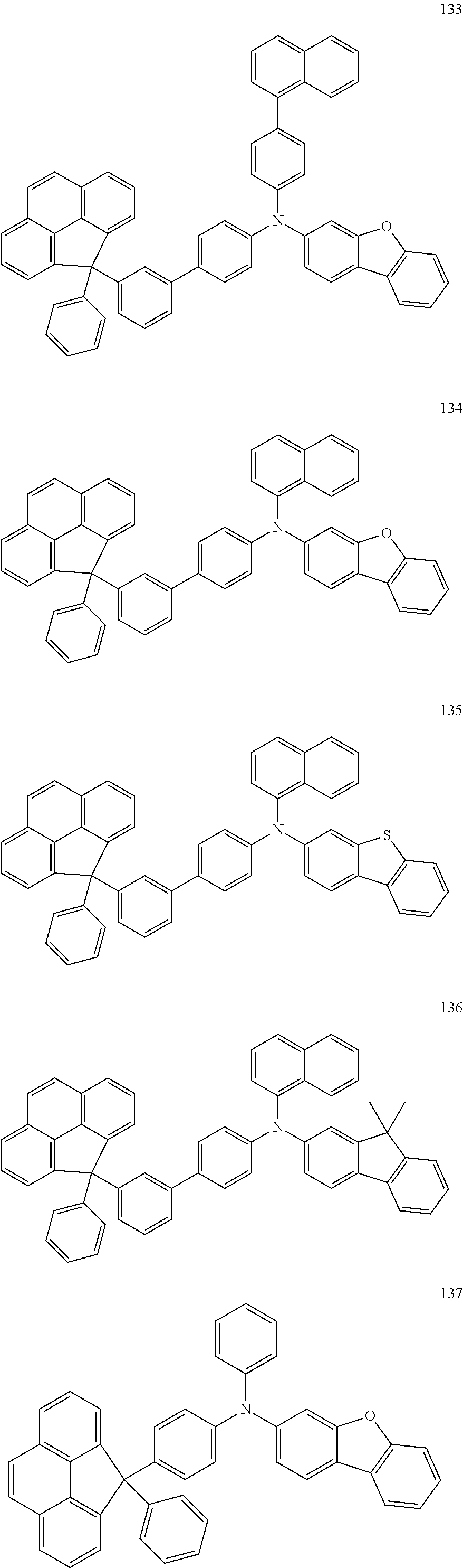


Applications Claiming Priority (2)
| Application Number | Priority Date | Filing Date | Title |
|---|---|---|---|
| KR1020150179445A KR20170071683A (en) | 2015-12-15 | 2015-12-15 | Amine compound and organic light emitting device including the same |
| KR10-2015-0179445 | 2015-12-15 |
Publications (2)
| Publication Number | Publication Date |
|---|---|
| US20170170402A1 US20170170402A1 (en) | 2017-06-15 |
| US10361374B2 true US10361374B2 (en) | 2019-07-23 |
Family
ID=59018421
Family Applications (1)
| Application Number | Title | Priority Date | Filing Date |
|---|---|---|---|
| US15/199,764 Active US10361374B2 (en) | 2015-12-15 | 2016-06-30 | Amine compound and organic light emitting device including the same |
Country Status (4)
| Country | Link |
|---|---|
| US (1) | US10361374B2 (en) |
| JP (1) | JP6898084B2 (en) |
| KR (1) | KR20170071683A (en) |
| CN (1) | CN106883131A (en) |
Families Citing this family (5)
| Publication number | Priority date | Publication date | Assignee | Title |
|---|---|---|---|---|
| KR101857632B1 (en) | 2018-02-02 | 2018-05-14 | 덕산네오룩스 주식회사 | Compound for organic electronic element, organic electronic element using the same, and an electronic device thereof |
| JP6748335B1 (en) * | 2019-03-15 | 2020-08-26 | 出光興産株式会社 | Compound, material for organic electroluminescence device, organic electroluminescence device and electronic device |
| CN114591257A (en) * | 2022-03-29 | 2022-06-07 | 京东方科技集团股份有限公司 | Spiro compound, electron transport material, and light-emitting device |
| CN115403508A (en) * | 2022-09-30 | 2022-11-29 | 长春海谱润斯科技股份有限公司 | Triarylamine derivative and organic electroluminescent device thereof |
| CN115594652A (en) * | 2022-09-30 | 2023-01-13 | 长春海谱润斯科技股份有限公司(Cn) | Amine compound and organic light-emitting device thereof |
Citations (13)
| Publication number | Priority date | Publication date | Assignee | Title |
|---|---|---|---|---|
| JP2004315495A (en) | 2002-09-20 | 2004-11-11 | Tosoh Corp | New arylamine derivative having fluorene skeleton, synthetic intermediate of the same, method for producing them and organic el element |
| KR20070084110A (en) | 2004-11-10 | 2007-08-24 | 이데미쓰 고산 가부시키가이샤 | Organic electroluminescent element |
| JP2009029726A (en) | 2007-07-25 | 2009-02-12 | Toyo Ink Mfg Co Ltd | Compound having carbazolyl group and use thereof |
| JP2009267255A (en) | 2008-04-28 | 2009-11-12 | Idemitsu Kosan Co Ltd | Material for organic electroluminescent element and organic electroluminescent element using the material |
| WO2010074440A2 (en) | 2008-12-24 | 2010-07-01 | 제일모직 주식회사 | High molecular weight polymers, organic photoelectric device including the same, and display device including the organic photoelectric device |
| WO2010137601A1 (en) | 2009-05-29 | 2010-12-02 | Semiconductor Energy Laboratory Co., Ltd. | Fluorene derivative, light-emitting element, light-emitting device, electronic device, and lighting device |
| JP2012046478A (en) | 2009-10-22 | 2012-03-08 | Semiconductor Energy Lab Co Ltd | Fluorene derivative, light-emitting element, light-emitting device, electronic equipment and lighting unit |
| KR20120118563A (en) * | 2011-04-19 | 2012-10-29 | 단국대학교 산학협력단 | Cyclopentafluorene compound and organic light emitting device including the same |
| KR101211091B1 (en) | 2009-09-16 | 2012-12-12 | 주식회사 진웅산업 | Light-emitting compound and organic light-emitting device using the same |
| US20130328021A1 (en) * | 2012-06-12 | 2013-12-12 | Samsung Display Co., Ltd. | Compound for organic light-emitting device and organic light-emitting device including the same |
| WO2015046955A1 (en) | 2013-09-26 | 2015-04-02 | Rohm And Haas Electronic Materials Korea Ltd. | Novel organic electroluminescent compound and organic electroluminescent device comprising the same |
| WO2015050391A1 (en) | 2013-10-02 | 2015-04-09 | Rohm And Haas Electronic Materials Korea Ltd. | An organic electroluminescent compound and an organic electroluminescent device comprising the same |
| KR20150106668A (en) * | 2014-03-12 | 2015-09-22 | (주)피엔에이치테크 | Novel compound for organic electroluminescent device and organic electroluminescent device comprising the same |
Family Cites Families (6)
| Publication number | Priority date | Publication date | Assignee | Title |
|---|---|---|---|---|
| KR101359630B1 (en) * | 2006-10-23 | 2014-02-10 | 삼성디스플레이 주식회사 | Organoelectroluminescent compound and organoelectroluminescent device employing the same |
| KR101990553B1 (en) * | 2012-04-17 | 2019-06-19 | 삼성디스플레이 주식회사 | Novel compound for organic light emitting device and organic light emitting device comprising the same |
| KR102075526B1 (en) * | 2013-01-04 | 2020-02-11 | 삼성디스플레이 주식회사 | Fluorene-based compound and organic light emitting diode comprising the same |
| CN104557668A (en) * | 2013-10-23 | 2015-04-29 | 海洋王照明科技股份有限公司 | Carbazolyl blue phosphorescent host material, preparation method thereof and organic electroluminescent device |
| WO2015174640A1 (en) * | 2014-05-13 | 2015-11-19 | 삼성에스디아이 주식회사 | Compound, organic optoelectronic element comprising same and display device thereof |
| JP2016111065A (en) * | 2014-12-02 | 2016-06-20 | 三星ディスプレイ株式會社Samsung Display Co.,Ltd. | Organic electroluminescent element |
-
2015
- 2015-12-15 KR KR1020150179445A patent/KR20170071683A/en active IP Right Grant
-
2016
- 2016-06-30 US US15/199,764 patent/US10361374B2/en active Active
- 2016-11-02 CN CN201610945115.7A patent/CN106883131A/en active Pending
- 2016-12-05 JP JP2016235499A patent/JP6898084B2/en active Active
Patent Citations (13)
| Publication number | Priority date | Publication date | Assignee | Title |
|---|---|---|---|---|
| JP2004315495A (en) | 2002-09-20 | 2004-11-11 | Tosoh Corp | New arylamine derivative having fluorene skeleton, synthetic intermediate of the same, method for producing them and organic el element |
| KR20070084110A (en) | 2004-11-10 | 2007-08-24 | 이데미쓰 고산 가부시키가이샤 | Organic electroluminescent element |
| JP2009029726A (en) | 2007-07-25 | 2009-02-12 | Toyo Ink Mfg Co Ltd | Compound having carbazolyl group and use thereof |
| JP2009267255A (en) | 2008-04-28 | 2009-11-12 | Idemitsu Kosan Co Ltd | Material for organic electroluminescent element and organic electroluminescent element using the material |
| WO2010074440A2 (en) | 2008-12-24 | 2010-07-01 | 제일모직 주식회사 | High molecular weight polymers, organic photoelectric device including the same, and display device including the organic photoelectric device |
| WO2010137601A1 (en) | 2009-05-29 | 2010-12-02 | Semiconductor Energy Laboratory Co., Ltd. | Fluorene derivative, light-emitting element, light-emitting device, electronic device, and lighting device |
| KR101211091B1 (en) | 2009-09-16 | 2012-12-12 | 주식회사 진웅산업 | Light-emitting compound and organic light-emitting device using the same |
| JP2012046478A (en) | 2009-10-22 | 2012-03-08 | Semiconductor Energy Lab Co Ltd | Fluorene derivative, light-emitting element, light-emitting device, electronic equipment and lighting unit |
| KR20120118563A (en) * | 2011-04-19 | 2012-10-29 | 단국대학교 산학협력단 | Cyclopentafluorene compound and organic light emitting device including the same |
| US20130328021A1 (en) * | 2012-06-12 | 2013-12-12 | Samsung Display Co., Ltd. | Compound for organic light-emitting device and organic light-emitting device including the same |
| WO2015046955A1 (en) | 2013-09-26 | 2015-04-02 | Rohm And Haas Electronic Materials Korea Ltd. | Novel organic electroluminescent compound and organic electroluminescent device comprising the same |
| WO2015050391A1 (en) | 2013-10-02 | 2015-04-09 | Rohm And Haas Electronic Materials Korea Ltd. | An organic electroluminescent compound and an organic electroluminescent device comprising the same |
| KR20150106668A (en) * | 2014-03-12 | 2015-09-22 | (주)피엔에이치테크 | Novel compound for organic electroluminescent device and organic electroluminescent device comprising the same |
Non-Patent Citations (2)
| Title |
|---|
| Machine English translation of KR-10-2015-0106668. Dec. 5, 2017. * |
| Machine English translation of Lee et al. (KR 10-2012-0118563). Jul. 15, 2017. * |
Also Published As
| Publication number | Publication date |
|---|---|
| JP2017109992A (en) | 2017-06-22 |
| KR20170071683A (en) | 2017-06-26 |
| CN106883131A (en) | 2017-06-23 |
| US20170170402A1 (en) | 2017-06-15 |
| JP6898084B2 (en) | 2021-07-07 |
Similar Documents
| Publication | Publication Date | Title |
|---|---|---|
| US20230106293A1 (en) | Organic electroluminescent element and electronic device | |
| US10079348B2 (en) | Material for organic electroluminescent device and organic electroluminescent device comprising same | |
| US9899601B2 (en) | Material for organic electroluminescent device and organic electroluminescent device including the same | |
| US20160293843A1 (en) | Material for an organic electroluminescent device and organic electroluminescent device using the same | |
| US10586927B2 (en) | Organic electroluminescent material and organic electroluminescent device including the same | |
| KR102522581B1 (en) | A material for organic electroluminescent device and organic electroluminescent device including the same | |
| US8987462B2 (en) | Compound and organic light-emitting device comprising the same | |
| US10361374B2 (en) | Amine compound and organic light emitting device including the same | |
| US20170213980A1 (en) | Material for organic electroluminescent device and organic electroluminescent device using the same | |
| US9871204B2 (en) | Material for organic electroluminescence device and organic electroluminescence device using the same | |
| US10147886B2 (en) | Organic electroluminescent material and organic electroluminescent device including the same | |
| US20140138633A1 (en) | Organic light-emitting device | |
| US20140027723A1 (en) | Organic light emitting device including compounds | |
| US20160118595A1 (en) | Material for use in organic electroluminescent device and organic electroluminescent device using the same | |
| JP6556995B2 (en) | Material for organic electroluminescence device and organic electroluminescence device using the same | |
| JP2017022194A (en) | Material for organic electroluminescence element and organic electroluminescence element using the same | |
| US20160285006A1 (en) | Material for an organic electroluminescent device and electroluminescent device using the same | |
| US9997713B2 (en) | Organic light-emitting device | |
| KR102549841B1 (en) | Amine compound and organic electroluminescence device including the same | |
| KR102440868B1 (en) | Amine derivatives, organic electroluminescence material and organic electroluminescence device including the same | |
| KR102657564B1 (en) | Amine compound and organic electroluminescence device including the same | |
| JP2016124792A (en) | Material for organic electroluminescent element and organic electroluminescent element prepared therewith | |
| KR20170100709A (en) | Amine compound and organic electroluminescence device including the same |
Legal Events
| Date | Code | Title | Description |
|---|---|---|---|
| AS | Assignment |
Owner name: SAMSUNG DISPLAY CO., LTD., KOREA, REPUBLIC OF Free format text: ASSIGNMENT OF ASSIGNORS INTEREST;ASSIGNOR:ITOI, HIROAKI;REEL/FRAME:039064/0825 Effective date: 20160426 |
|
| STPP | Information on status: patent application and granting procedure in general |
Free format text: NOTICE OF ALLOWANCE MAILED -- APPLICATION RECEIVED IN OFFICE OF PUBLICATIONS |
|
| STPP | Information on status: patent application and granting procedure in general |
Free format text: PUBLICATIONS -- ISSUE FEE PAYMENT VERIFIED |
|
| STCF | Information on status: patent grant |
Free format text: PATENTED CASE |
|
| CC | Certificate of correction | ||
| MAFP | Maintenance fee payment |
Free format text: PAYMENT OF MAINTENANCE FEE, 4TH YEAR, LARGE ENTITY (ORIGINAL EVENT CODE: M1551); ENTITY STATUS OF PATENT OWNER: LARGE ENTITY Year of fee payment: 4 |