US10352339B2 - Low-noise decompression device and combustion device - Google Patents
Low-noise decompression device and combustion device Download PDFInfo
- Publication number
- US10352339B2 US10352339B2 US15/038,231 US201415038231A US10352339B2 US 10352339 B2 US10352339 B2 US 10352339B2 US 201415038231 A US201415038231 A US 201415038231A US 10352339 B2 US10352339 B2 US 10352339B2
- Authority
- US
- United States
- Prior art keywords
- orifice
- jet
- orifice plate
- flow
- duct
- Prior art date
- Legal status (The legal status is an assumption and is not a legal conclusion. Google has not performed a legal analysis and makes no representation as to the accuracy of the status listed.)
- Active, expires
Links
Images


Classifications
-
- F—MECHANICAL ENGINEERING; LIGHTING; HEATING; WEAPONS; BLASTING
- F15—FLUID-PRESSURE ACTUATORS; HYDRAULICS OR PNEUMATICS IN GENERAL
- F15D—FLUID DYNAMICS, i.e. METHODS OR MEANS FOR INFLUENCING THE FLOW OF GASES OR LIQUIDS
- F15D1/00—Influencing flow of fluids
- F15D1/009—Influencing flow of fluids by means of vortex rings
-
- F—MECHANICAL ENGINEERING; LIGHTING; HEATING; WEAPONS; BLASTING
- F15—FLUID-PRESSURE ACTUATORS; HYDRAULICS OR PNEUMATICS IN GENERAL
- F15D—FLUID DYNAMICS, i.e. METHODS OR MEANS FOR INFLUENCING THE FLOW OF GASES OR LIQUIDS
- F15D1/00—Influencing flow of fluids
- F15D1/02—Influencing flow of fluids in pipes or conduits
-
- F—MECHANICAL ENGINEERING; LIGHTING; HEATING; WEAPONS; BLASTING
- F16—ENGINEERING ELEMENTS AND UNITS; GENERAL MEASURES FOR PRODUCING AND MAINTAINING EFFECTIVE FUNCTIONING OF MACHINES OR INSTALLATIONS; THERMAL INSULATION IN GENERAL
- F16L—PIPES; JOINTS OR FITTINGS FOR PIPES; SUPPORTS FOR PIPES, CABLES OR PROTECTIVE TUBING; MEANS FOR THERMAL INSULATION IN GENERAL
- F16L55/00—Devices or appurtenances for use in, or in connection with, pipes or pipe systems
- F16L55/02—Energy absorbers; Noise absorbers
- F16L55/027—Throttle passages
- F16L55/02709—Throttle passages in the form of perforated plates
- F16L55/02718—Throttle passages in the form of perforated plates placed transversely
-
- F—MECHANICAL ENGINEERING; LIGHTING; HEATING; WEAPONS; BLASTING
- F23—COMBUSTION APPARATUS; COMBUSTION PROCESSES
- F23C—METHODS OR APPARATUS FOR COMBUSTION USING FLUID FUEL OR SOLID FUEL SUSPENDED IN A CARRIER GAS OR AIR
- F23C5/00—Disposition of burners with respect to the combustion chamber or to one another; Mounting of burners in combustion apparatus
- F23C5/08—Disposition of burners
- F23C5/32—Disposition of burners to obtain rotating flames, i.e. flames moving helically or spirally
-
- F—MECHANICAL ENGINEERING; LIGHTING; HEATING; WEAPONS; BLASTING
- F23—COMBUSTION APPARATUS; COMBUSTION PROCESSES
- F23K—FEEDING FUEL TO COMBUSTION APPARATUS
- F23K5/00—Feeding or distributing other fuel to combustion apparatus
- F23K5/002—Gaseous fuel
- F23K5/007—Details
-
- F—MECHANICAL ENGINEERING; LIGHTING; HEATING; WEAPONS; BLASTING
- F15—FLUID-PRESSURE ACTUATORS; HYDRAULICS OR PNEUMATICS IN GENERAL
- F15D—FLUID DYNAMICS, i.e. METHODS OR MEANS FOR INFLUENCING THE FLOW OF GASES OR LIQUIDS
- F15D1/00—Influencing flow of fluids
- F15D1/02—Influencing flow of fluids in pipes or conduits
- F15D1/025—Influencing flow of fluids in pipes or conduits by means of orifice or throttle elements
-
- F—MECHANICAL ENGINEERING; LIGHTING; HEATING; WEAPONS; BLASTING
- F23—COMBUSTION APPARATUS; COMBUSTION PROCESSES
- F23K—FEEDING FUEL TO COMBUSTION APPARATUS
- F23K2400/00—Pretreatment and supply of gaseous fuel
- F23K2400/20—Supply line arrangements
-
- F23K2401/20—
Definitions
- the present invention relates to a low-noise decompression device to be disposed in a fuel-gas supply duct or the like for supplying fuel gas to a boiler, for instance, and a combustion device including the low-noise decompression device.
- a boiler combusts fuel to heat water and produce steam.
- Fuel gas is supplied from a fuel supply source to a burner disposed in a gas-fired boiler through a duct, and a decompression device is disposed in the duct to adjust a fuel-supply pressure to the burner.
- Patent Document 1 discloses a decompression device applied to a liquid-transfer duct. This decompression device has an uneven section with a wavy cross section formed on an inner wall of a duct forming a flow passage, and a plurality of sheets of mesh metal disposed entirely over a transverse plane inside the duct.
- Patent Document 2 discloses a decompression device including a plurality of stages of perforated orifice plates disposed in a flow direction in a flow passage, and mesh-shaped porous metal disposed between the perforated orifice plates.
- the apertures on the perforated orifice plates have a diameter increasing toward downstream stages, and each aperture is disposed so that apertures on the next stage are invisible when seen from an upstream side toward a downstream side.
- Patent Document 1 JPS60-60304A
- Patent Document 2 JPH07-5357U (Utility Model)
- Patent Document 1 Since the decompression device disclosed in Patent Document 1 has an uneven section with a wavy cross section formed on an inner wall of a duct forming a flow passage, a large amount of processing time is required, and a troublesome work is required to provide a plurality of sheets of metal mesh entirely over a transverse plane inside the duct.
- FIG. 8 is a diagram of a typical compression device with a plurality of orifice plates disposed in a flow passage, as disclosed in Patent Document 2.
- an upstream orifice plate 104 and a downstream orifice plate 108 are disposed in a flow passage for a fluid F formed inside a duct 102 .
- a total opening area of orifices 110 formed on the downstream orifice plate 108 is larger than a total opening area of an orifice 106 formed on the upstream orifice plate 104 .
- the decompression device can create pressure loss to function as a decompression device.
- the orifice 106 and the orifices 110 are disposed on different positions on a flow-passage cross section. In this way, the fluid F is blocked and a kinetic pressure of the fluid F is reduced.
- Karman vortices e are periodically generated downstream of the orifice 106 .
- St is a Strouhal number
- V is a flow rate (m/s) of the fluid F
- L is an orifice interval (m)
- h is an orifice thickness (m).
- a flow-passage space R surrounded by the upstream orifice plate 104 and the downstream orifice plate 108 has a unique vibrational mode determined by a physical property of the fluid F. If the unique vibrational frequency or its multiple matches the generation frequency fk, gas-column resonance is excited and noise is generated in the flow-passage space R.
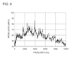
- FIG. 9 is a graph showing a noise level generated by the decompression device 100 .
- X-axis in this graph represents a frequency of noise generation.
- FIG. 9 shows that noise having a sharp peak frequency is generated when the unique vibrational frequency of the flow-passage space R matches the generation frequency fk of Karman vortices e.
- a plurality of Karman vortices e is generated at positions dispersed in the circumferential direction of the orifice 106 and at the same position in a duct axial direction, in the vicinity of an outlet rim portion of the orifice 106 of the upstream orifice plate 104 , and generation of Karman vortices e generates vibrational waves.
- the vibrational waves generated by respective Karman vortices e propagate to the downstream orifice plate 108 at the same phase to be reflected.
- vibrational waves generated by subsequently-produced Karman vortices are amplified by the reflected waves of the same phase reflected by the downstream orifice plate 108 .
- large noise may be produced.
- an object of the present invention is to provide a decompression device which includes a plurality of stages of orifice plates disposed in a flow passage and which produces less noise in response to sonic feedback phenomenon and gas-column resonance.
- a low-noise decompression device comprises: a duct forming a flow passage for a fluid; an upstream orifice plate disposed in the flow passage and having an orifice; a downstream orifice plate disposed in the flow passage and downstream of the upstream orifice plate; and a jet-flow interference part disposed only partially on an outlet rim portion of the orifice and configured to interfere with a jet flow discharged from the orifice.
- Karman vortices generated at different positions in a duct axial direction have different generation frequencies from one another, which makes it possible to reduce incidence of gas-column resonance. Accordingly, it is possible to suppress sonic feedback phenomenon and to prevent gas-column resonance, which makes it possible to reduce generation of noise in a flow-passage space between the upstream orifice plate and the downstream orifice plate effectively.
- the jet-flow interference part may be disposed on a position where the jet-flow interference part can interfere with a jet flow discharged from the orifice of the upstream orifice plate. Further, the jet-flow interference part may be disposed partially on the outlet rim portion of the orifice, and a region with the jet-flow interference part and a region without the jet-flow interference part may coexist in the circumferential direction of the orifice.
- the jet-flow interference part comprises a rod-shaped member extending along a tangent direction of the orifice. In this way, it is possible to form the jet-flow interference part readily and at lower cost.
- the rod-shaped member is a block-shaped member having a quadrilateral cross section. In this way, it is possible to form the jet-flow interference part readily and at lower cost even further.
- the jet-flow interference part has a curved surface extending along the axial direction of the duct and curving along the outlet rim portion of the orifice. In this way, it is possible to form the jet-flow interference part readily and at lower cost even further along the outlet rim portion of the orifice.
- a recess portion is formed on a part of a wall surface forming the outlet rim portion of the orifice of the upstream orifice plate, and the jet-flow interference part comprises a part of the wall surface without the recess portion. In this way, it is possible to form the jet-flow interference part readily and at lower cost.
- the jet-flow interference part has a length, in an axial direction of the duct, of from one to two times a diameter of the orifice.
- a combustion device comprises: the above low-noise decompression device; and a burner disposed on a terminating end of a fuel-gas supply duct which is the duct, the burner being configured to combust fuel gas which is the fluid and which has a pressure reduced by the low-noise decompression device.
- the fuel gas supply duct including the low-noise decompression device according to the present invention it is possible to reduce noise in the fuel gas supply duct effectively.
- the jet-flow interference part being provided only partially on the outlet rim portion of the orifice of the upstream orifice plate, it is possible to suppress sonic feedback phenomenon and to prevent gas-column resonance phenomenon, which makes it possible to reduce noise generated in a decompression device effectively.
- FIG. 1 is a front cross-sectional view of a decompression device according to the first embodiment of the present invention.
- FIG. 2 is a view in a direction of arrow A from FIG. 1 .
- FIG. 3 is a view in a direction of arrow B from FIG. 1 .
- FIG. 4 is a partial perspective view of a decompression device according to the second embodiment of the present invention.
- FIG. 5 is a partial front cross-sectional view of a decompression device according to the third embodiment of the present invention.
- FIG. 6 is a partial perspective view of the decompression device depicted in FIG. 5 .
- FIG. 7 is a perspective view of a combustion device according to an embodiment of the present invention.
- FIG. 8 is a front cross-sectional view of a typical decompression device.
- FIG. 9 is a graph showing a relationship between a frequency and a noise level of noise generated in a flow-passage space.
- FIGS. 1 to 3 A decompression device according to the first embodiment of the present invention will be described with reference to FIGS. 1 to 3 .
- a flow passage is formed inside a duct 12 , and a fluid F flows through the flow passage in a direction of the arrow.
- the decompression device 10 of the present embodiment includes an upstream orifice plate 14 disposed inside the duct 12 , and a downstream orifice plate 16 disposed downstream of the upstream orifice plate 14 .
- the upstream orifice plate 14 and the downstream orifice plate 16 are disposed so as to traverse the flow passage formed inside the duct 12 , i.e., in a direction orthogonal to an inner surface 12 a of the duct 12 .
- the upstream orifice plate 14 has one orifice 18 of a circular shape formed in center, and the downstream orifice plate 16 has four orifices 20 of a circular shape.
- the four orifices 20 are disposed symmetrically and centered at the center point O of the downstream orifice plate 16 .
- An opening area of the orifice 18 is smaller than the total opening area of the orifices 20 .
- the orifices 20 are disposed on such positions that the orifices 20 are invisible if seen from the orifice 18 toward downstream.
- the orifices 18 and 20 are disposed on the upstream orifice plate 14 and the downstream orifice plate 16 , respectively, so that projection of the orifice 18 in an axial direction of the duct 12 (hereinafter, also referred to as a duct axial direction) does not overlap with the orifices 20 .
- the decompression device can create pressure loss by blocking the fluid F to function as a decompression device.
- a jet-flow interference part 22 A is fixed at an outlet rim portion of the orifice 18 , with respect to a fluid flow direction, and on a back surface of the upstream orifice plate 14 , with respect to the fluid flow direction.
- the jet-flow interference part 22 A includes two block-shaped members 24 a , 24 b .
- the block-shaped members 24 a , 24 b have a quadrilateral cross section and a linear shape in the longitudinal direction.
- the block-shaped members 24 a , 24 b extend along a tangent direction of the orifice 18 so as to contact a part of the outlet rim portion of the orifice 18 .
- the block-shaped member 24 a is disposed so as to extend in the horizontal direction orthogonal to the duct 12 at an upper part of the outlet of the orifice 18
- the block-shaped member 24 b is disposed so as to extend in the horizontal direction orthogonal to the duct 12 at a lower part of the outlet of the orifice 18 .
- the block-shaped members 24 a , 24 b are disposed on positions of interference by a jet flow discharged from the orifice 18 .
- the block-shaped members 24 a , 24 b have flat side surfaces 25 a , 25 b , respectively, extending along the duct axial direction from the outlet rim portion of the orifice 18 .
- a position of interference by a jet flow is, in other words, a position to be contacted by a jet flow.
- generation regions of Karman vortices e in the duct axial direction are different between a region with the jet-flow interference part 22 A and a region r without the jet-flow interference part 22 A, in the circumferential direction of the orifice 18 .
- a wall surface of the orifice 18 is substantially elongated in the duct axial direction and generation positions of Karman vortices e are offset toward downstream in a region with the jet-flow interference part 22 A, as compared to a region r without the jet-flow interference part 22 A.
- a plurality of vibrational waves generated by a plurality of produced Karman vortices e propagates to the downstream orifice plate 16 at phases different from one another.
- vibrational waves generated by subsequently-produced Karman vortices e may be no longer amplified by reflected waves of the vibrational waves reflected by the downstream orifice plate 16 .
- Karman vortices e generated at different positions in the duct axial direction have different generation frequencies fk, which makes it possible to reduce incidence of gas-column resonance. Accordingly, it is possible to reduce generation of noise in the flow-passage space R between the upstream orifice plate 14 and the downstream orifice plate 16 effectively.
- block-shaped members 24 a , 24 b being provided as the jet-flow interference part 22 A, it is possible to install the jet-flow interference part 22 A readily and at lower cost.
- the length C of a jet-flow interference member in the duct axial direction which is the length C of the block-shaped members 24 a , 24 b in the duct axial direction, is from one to two times the diameter of the orifice 18 , it is possible to achieve a sufficient positional difference in the duct axial direction between generation positions of Karman vortices e in a region with the jet-flow interference part 22 A and generation positions of Karman vortices e in a region r without the jet-flow interference part 22 A, in the circumferential direction of the orifice 18 , and there is no longer a risk of affecting a decompression effect of the decompression device 10 .
- the length C of the block-shaped members 24 a , 24 b in the duct axial direction may be from one to two times the diameter of the orifice 18 .
- the width of the block-shaped members 24 a , 24 b in the radial direction of the orifice 18 is the same as the diameter d of the orifice 18 , for instance.
- the jet-flow interference part 22 A may include only one of the block-shaped members 24 a , 24 b , whereby a noise-reduction effect can still be achieved.
- the decompression device 10 B includes the orifice 18 of a circular shape formed in center of the upstream orifice plate 14 , similarly to the first embodiment.
- a jet-flow interference part 22 B of the present embodiment includes a jet-flow interference member 26 disposed on a back surface of the upstream orifice plate 14 with respect to the fluid flow direction.
- the jet-flow interference member 26 has a semi-cylindrical shape and is disposed concentric with the orifice 18 and along the outlet rim portion of the orifice 18 .
- the jet-flow interference member 26 extends along the duct axial direction and has a quadrilateral cross section in a direction along the radial direction of the orifice 18 .
- the jet-flow interference member 26 has a curved semi-arc shape along the outlet rim portion of the orifice 18 .
- An inner side surface of the jet-flow interference member 26 is formed into a semi-arc shape, i.e., a curved surface, and is disposed along the outlet rim portion of the orifice 18 .
- the configuration is otherwise the same as that of the first embodiment, including the downstream orifice plate 16 .
- the jet-flow interference member 26 is disposed on a position of interference by a jet flow discharged from the orifice 18 .
- a jet flow discharged from the outlet of the orifice 18 spreads out as represented by dotted lines s 1 in FIG. 4 , and Karman vortices e are generated downstream of the jet-flow interference member 26 .
- a jet flow spreads out as represented by dotted lines s 2 In a region without the jet-flow interference member 26 (region r in FIG. 4 ), a jet flow spreads out as represented by dotted lines s 2 , and Karman vortices e are generated immediately downstream of the orifice 18 .
- Karman vortices e generated at different positions in the duct axial direction have different generation frequencies fk, which makes it possible to reduce incidence of gas-column resonance. Accordingly, it is possible to reduce generation of noise in the flow-passage space R between the upstream orifice plate 14 and the downstream orifice plate 16 effectively.
- jet-flow interference member 26 being provided as the jet-flow interference part 22 B, it is possible to install the jet-flow interference part 22 B readily and at lower cost.
- a position to provide the jet-flow interference member 26 in the circumferential direction of the orifice 18 is not particularly limited.
- the interference member 26 can be disposed on an upper side, a lower side, or a lateral side of the outlet rim portion of the orifice 18 .
- a decompression device 10 C includes the orifice 18 of a circular shape formed in center of the upstream orifice plate 14 , similarly to the first embodiment.
- recess portions 28 are formed on four positions on the outlet rim portion of the orifice 18 .
- the recess portions 28 are formed on a part of a wall surface (inner peripheral surface) forming the orifice 18 .
- the recess portions 28 have a fan shape as seen in the duct axial direction, and have the same length in the circumferential direction and the same central angle with one another.
- the recess portions 28 extend in the duct axial direction, and have a quadrilateral cross section along the radial direction of the orifice 18 .
- the recess portions 28 have an opening on the wall surface forming the orifice 18 .
- the recess portions 28 are disposed at regular intervals in the circumferential direction of the orifice 18 . Accordingly, there are four regions r with no recess portion 28 formed between the recess portions 28 , and wall-surface portions each disposed between adjacent two of the recess portions 28 form a jet-flow interference part 22 C.
- the length in the circumferential direction of each recess portion 28 and the length in the circumferential direction of each region r are equal to each other.
- the configuration is otherwise the same as that of the first embodiment, including the downstream orifice plate 16 .
- the length of the orifice 18 in the duct axial direction is relatively shortened in the regions with the recess portions 28
- the length of the orifice 18 in the duct axial direction is relatively elongated in the regions r without the recess portions 28 . Accordingly, it can be said that the jet-flow interference part 22 C is disposed on the outlet rim portion of the orifice 18 of the upstream orifice plate 14 in the regions r (see FIG. 6 ) without the recess portions 28 .
- a jet flow of the fluid F discharged from the orifice 18 spreads out as represented by dotted lines s 1 in FIGS. 5 and 6 , and Karman vortices e are generated immediately downstream of the back surface of the upstream orifice plate 14 in the fluid flow direction.
- a jet flow spreads out as represented by dotted lines s 2 and Karman vortices e are generated immediately downstream of bottom surfaces of the recess portions 28 .
- the bottom surfaces of the recess portions 28 are disposed upstream of the back surface of the upstream orifice plate 14 with respect to the fluid flow direction.
- Karman vortices e generated at different positions in the duct axial direction have different generation frequencies fk, which reduces incidence of gas-column resonance. Accordingly, it is possible to suppress sonic feedback phenomenon and prevent resonance phenomenon, which makes it possible to reduce generation of noise.
- jet-flow interference part 22 C by a simple machining process of forming the recess portions 28 on the upstream orifice plate 14 , which makes it possible to form the jet-flow interference part 22 C readily and at less cost.
- fuel gas g is introduced in to a fuel gas introduction duct 32 from a fuel gas supply source (not depicted).
- the fuel gas introduction duct 32 is connected to a fuel gas collective duct 34 .
- a plurality of fuel gas branch ducts 36 is connected to the fuel gas collective duct 34 .
- a gas burner 38 is disposed on a terminating end of each fuel gas branch duct 36 .
- the gas burner 38 is, for instance, mounted to a partition wall of a boiler furnace.
- the gas burner 38 includes a stopper nozzle 40 which is attached to the terminating end of each fuel gas branch duct 36 and which has a tapered housing, and a gas nozzle 42 connected to an end surface of the stopper nozzle 40 .
- Fuel gas g is discharged from a plurality of nozzle holes 40 a formed on the end surface of the stopper nozzle 40 , and is supplied into the boiler furnace, for instance, from the gas nozzle 42 .
- the decompression device 10 which is selected from the decompression devices 10 A to 10 C of the above respective embodiments, is disposed in the fuel gas introduction duct 32 and the fuel gas branch ducts 36 .
- the decompression device 10 being provided in the fuel gas introduction duct 32 and the fuel gas branch ducts 36 , it is possible to reduce noise generated in the fuel gas introduction duct 32 and the fuel gas branch ducts 36 effectively. Further, it is possible to install the decompression device 10 readily and at lower cost.
Abstract
Description
fk=St·V/(L+h), (1)
- 10, 10A, 10B, 10C, 100 Decompression device
- 12, 102 Duct
- 14, 104 Upstream orifice plate
- 16, 108 Downstream orifice plate
- 18, 20, 106, 110 Orifice
- 22A, 22B, 22C Jet-flow interference part
- 24 a, 24 b Block-shaped member
- 26 Interference member
- 28 Recess portion
- 30 Combustion device
- 32 Fuel gas introduction duct
- 34 Fuel gas collective duct
- 36 Fuel gas branch duct
- 38 Gas burner
- 40 Stopper nozzle
- 42 Gas nozzle
- e Karman vortex
- g Fuel gas
- s1, s2 Jet flow
Claims (7)
Applications Claiming Priority (3)
| Application Number | Priority Date | Filing Date | Title |
|---|---|---|---|
| JP2013271373 | 2013-12-27 | ||
| JP2013-271373 | 2013-12-27 | ||
| PCT/JP2014/080953 WO2015098389A1 (en) | 2013-12-27 | 2014-11-21 | Low-noise pressure reduction device and combustion device |
Publications (2)
| Publication Number | Publication Date |
|---|---|
| US20160290373A1 US20160290373A1 (en) | 2016-10-06 |
| US10352339B2 true US10352339B2 (en) | 2019-07-16 |
Family
ID=53478261
Family Applications (1)
| Application Number | Title | Priority Date | Filing Date |
|---|---|---|---|
| US15/038,231 Active 2035-06-09 US10352339B2 (en) | 2013-12-27 | 2014-11-21 | Low-noise decompression device and combustion device |
Country Status (4)
| Country | Link |
|---|---|
| US (1) | US10352339B2 (en) |
| JP (1) | JP6130929B2 (en) |
| CN (1) | CN105659019B (en) |
| WO (1) | WO2015098389A1 (en) |
Families Citing this family (5)
| Publication number | Priority date | Publication date | Assignee | Title |
|---|---|---|---|---|
| JP2016118282A (en) * | 2014-12-23 | 2016-06-30 | 日立建機株式会社 | Contraction valve |
| AU2017306897B2 (en) * | 2016-08-02 | 2019-07-04 | Shell Internationale Research Maatschappij B.V. | A piping system |
| WO2018123656A1 (en) * | 2016-12-26 | 2018-07-05 | 株式会社コーアツ | Jet head having silencing function for gas-based fire extinguishing equipment, and method for storing and assembling same |
| JP6295385B1 (en) * | 2017-04-07 | 2018-03-14 | 清 高浦 | Compressed air pressure stabilizer in air cylinder exhaust chamber |
| TWI668397B (en) * | 2018-11-23 | 2019-08-11 | 致茂電子股份有限公司 | Condensing system |
Citations (18)
| Publication number | Priority date | Publication date | Assignee | Title |
|---|---|---|---|---|
| US3680376A (en) | 1970-07-30 | 1972-08-01 | Foxboro Co | Low noise primary device for fluid flow measurement by head meter (signal noise) |
| US4142413A (en) * | 1976-06-08 | 1979-03-06 | N.V. Nederlandse Gasunie | Device for improving the flow profile in a gas line |
| JPS6060304A (en) | 1983-09-13 | 1985-04-06 | Chiyoda Chem Eng & Constr Co Ltd | Pressure reducing device of low-noise and low-vibration type |
| JPS6175505A (en) | 1984-09-21 | 1986-04-17 | 日本電気株式会社 | Manufacture of element for type variable resistor |
| JPH0425094A (en) | 1990-05-16 | 1992-01-28 | Matsushita Electric Works Ltd | Multilayer interconnection substrate |
| JPH0633917A (en) | 1992-07-15 | 1994-02-08 | Chiyoda Corp | Liquid pressure reducing device |
| JPH0650527A (en) | 1992-07-30 | 1994-02-22 | Mitsubishi Heavy Ind Ltd | Multi-stage pressure reducing device |
| JPH06185691A (en) | 1992-12-15 | 1994-07-08 | Mitsui Sekika Eng Kk | Control device for suppressing sound and vibration of liquid for liquid pipe line |
| JPH075357A (en) | 1993-01-11 | 1995-01-10 | Samsung Electron Co Ltd | Infinity-distance detection circuit of automatic focusing system |
| JP2001124280A (en) | 1999-10-29 | 2001-05-11 | Yamatake Corp | Orifice plate |
| JP2005009667A (en) | 2003-05-23 | 2005-01-13 | Psc Kk | Gas passage throttling device for nozzle flapper valve |
| JP2005155884A (en) | 2003-10-27 | 2005-06-16 | Sumitomo Metal Ind Ltd | Orifice body for decompression and valve |
| CN1820174A (en) | 2003-07-09 | 2006-08-16 | 达涅利机械工业有限公司 | A burner and gas-injection device |
| CN200972118Y (en) | 2006-11-17 | 2007-11-07 | 李建东 | Venturi oxygen-riched energy-saving burner |
| US20100096111A1 (en) * | 2008-10-20 | 2010-04-22 | Kucherov Yan R | Heat dissipation system with boundary layer disruption |
| CN102138050A (en) | 2008-09-04 | 2011-07-27 | 中外炉工业株式会社 | Continuous heating furnace |
| CN203300214U (en) | 2013-06-27 | 2013-11-20 | 赵旭 | Exhaust muffler structure |
| JP2015086968A (en) | 2013-10-31 | 2015-05-07 | 三菱日立パワーシステムズ株式会社 | Multistage decompression device and boiler |
Family Cites Families (5)
| Publication number | Priority date | Publication date | Assignee | Title |
|---|---|---|---|---|
| JPS57186796U (en) * | 1981-05-23 | 1982-11-26 | ||
| JPS60116493U (en) * | 1984-01-17 | 1985-08-06 | 三菱重工業株式会社 | pressure reducing device |
| JPH0338490Y2 (en) * | 1984-10-24 | 1991-08-14 | ||
| JPH075357Y2 (en) * | 1990-06-26 | 1995-02-08 | 三菱重工業株式会社 | Low noise multi-stage depressurizer |
| JPH08200584A (en) * | 1995-01-23 | 1996-08-06 | Hitachi Zosen Corp | Orifice |
-
2014
- 2014-11-21 WO PCT/JP2014/080953 patent/WO2015098389A1/en active Application Filing
- 2014-11-21 CN CN201480057678.1A patent/CN105659019B/en active Active
- 2014-11-21 JP JP2015554684A patent/JP6130929B2/en active Active
- 2014-11-21 US US15/038,231 patent/US10352339B2/en active Active
Patent Citations (18)
| Publication number | Priority date | Publication date | Assignee | Title |
|---|---|---|---|---|
| US3680376A (en) | 1970-07-30 | 1972-08-01 | Foxboro Co | Low noise primary device for fluid flow measurement by head meter (signal noise) |
| US4142413A (en) * | 1976-06-08 | 1979-03-06 | N.V. Nederlandse Gasunie | Device for improving the flow profile in a gas line |
| JPS6060304A (en) | 1983-09-13 | 1985-04-06 | Chiyoda Chem Eng & Constr Co Ltd | Pressure reducing device of low-noise and low-vibration type |
| JPS6175505A (en) | 1984-09-21 | 1986-04-17 | 日本電気株式会社 | Manufacture of element for type variable resistor |
| JPH0425094A (en) | 1990-05-16 | 1992-01-28 | Matsushita Electric Works Ltd | Multilayer interconnection substrate |
| JPH0633917A (en) | 1992-07-15 | 1994-02-08 | Chiyoda Corp | Liquid pressure reducing device |
| JPH0650527A (en) | 1992-07-30 | 1994-02-22 | Mitsubishi Heavy Ind Ltd | Multi-stage pressure reducing device |
| JPH06185691A (en) | 1992-12-15 | 1994-07-08 | Mitsui Sekika Eng Kk | Control device for suppressing sound and vibration of liquid for liquid pipe line |
| JPH075357A (en) | 1993-01-11 | 1995-01-10 | Samsung Electron Co Ltd | Infinity-distance detection circuit of automatic focusing system |
| JP2001124280A (en) | 1999-10-29 | 2001-05-11 | Yamatake Corp | Orifice plate |
| JP2005009667A (en) | 2003-05-23 | 2005-01-13 | Psc Kk | Gas passage throttling device for nozzle flapper valve |
| CN1820174A (en) | 2003-07-09 | 2006-08-16 | 达涅利机械工业有限公司 | A burner and gas-injection device |
| JP2005155884A (en) | 2003-10-27 | 2005-06-16 | Sumitomo Metal Ind Ltd | Orifice body for decompression and valve |
| CN200972118Y (en) | 2006-11-17 | 2007-11-07 | 李建东 | Venturi oxygen-riched energy-saving burner |
| CN102138050A (en) | 2008-09-04 | 2011-07-27 | 中外炉工业株式会社 | Continuous heating furnace |
| US20100096111A1 (en) * | 2008-10-20 | 2010-04-22 | Kucherov Yan R | Heat dissipation system with boundary layer disruption |
| CN203300214U (en) | 2013-06-27 | 2013-11-20 | 赵旭 | Exhaust muffler structure |
| JP2015086968A (en) | 2013-10-31 | 2015-05-07 | 三菱日立パワーシステムズ株式会社 | Multistage decompression device and boiler |
Non-Patent Citations (3)
| Title |
|---|
| International Preliminary Report on Patentability and translation of Written Opinion of the International Searching Authority dated Feb. 17, 2015 in corresponding International Application No. PCT/JP2014/080953. |
| International Search Report dated Feb. 17, 2015 in corresponding International Application No. PCT/JP2014/080953, with English translation. |
| Office Action dated Dec. 2, 2016 in corresponding Chinese Application No. 201480057678.1 (with English Translation). |
Also Published As
| Publication number | Publication date |
|---|---|
| JP6130929B2 (en) | 2017-05-17 |
| CN105659019B (en) | 2017-07-07 |
| CN105659019A (en) | 2016-06-08 |
| JPWO2015098389A1 (en) | 2017-03-23 |
| US20160290373A1 (en) | 2016-10-06 |
| WO2015098389A1 (en) | 2015-07-02 |
Similar Documents
| Publication | Publication Date | Title |
|---|---|---|
| US10352339B2 (en) | Low-noise decompression device and combustion device | |
| CA2664769C (en) | Burner, and combustion equipment and boiler comprising burner | |
| JP2013139773A (en) | Gas turbine inlet system | |
| US10323575B2 (en) | Gas turbine fuel pipe comprising a damper | |
| ITMO20100221A1 (en) | SILENCER DEVICE FOR HAIRDRYER. | |
| KR102044668B1 (en) | Gas turbine combustor having nozzle guide for combustion oscillation reduction | |
| EP3299716B1 (en) | Burner for gas apparatus | |
| JP6023133B2 (en) | Combustion device | |
| EP3167954B1 (en) | Static mixer | |
| TWI640724B (en) | Rear vent and combustion device provided with the same | |
| CN107975796B (en) | Burner with a burner head | |
| JP6700225B2 (en) | Silencer | |
| US9587826B2 (en) | Gas burner | |
| JP5378325B2 (en) | Tubular burner | |
| JP6336379B2 (en) | Combustion device | |
| JP2005147426A (en) | Heat exchanger | |
| JP5890243B2 (en) | Burner | |
| KR102101173B1 (en) | Noise damper | |
| JP7157095B2 (en) | combustor silencer | |
| JP2007247468A (en) | Exhaust gas muffler | |
| KR101439091B1 (en) | A desuperheater | |
| WO2017208406A1 (en) | Exhaust pipe | |
| JP2020002912A (en) | Exhaust emission control device and vehicle | |
| JP2022082241A (en) | Air supply duct for fan and combustion device including the same | |
| JP5513151B2 (en) | Tubular flame burner |
Legal Events
| Date | Code | Title | Description |
|---|---|---|---|
| AS | Assignment |
Owner name: MITSUBISHI HITACHI POWER SYSTEMS, LTD., JAPAN Free format text: ASSIGNMENT OF ASSIGNORS INTEREST;ASSIGNORS:SUGANUMA, NAOKI;OKIMOTO, TAKAHIRO;KAWAMOTO, NOBORU;AND OTHERS;REEL/FRAME:038973/0824 Effective date: 20160606 |
|
| STPP | Information on status: patent application and granting procedure in general |
Free format text: NOTICE OF ALLOWANCE MAILED -- APPLICATION RECEIVED IN OFFICE OF PUBLICATIONS |
|
| STPP | Information on status: patent application and granting procedure in general |
Free format text: PUBLICATIONS -- ISSUE FEE PAYMENT VERIFIED |
|
| STCF | Information on status: patent grant |
Free format text: PATENTED CASE |
|
| AS | Assignment |
Owner name: MITSUBISHI POWER, LTD., JAPAN Free format text: CHANGE OF NAME;ASSIGNOR:MITSUBISHI HITACHI POWER SYSTEMS, LTD.;REEL/FRAME:054975/0438 Effective date: 20200901 |
|
| MAFP | Maintenance fee payment |
Free format text: PAYMENT OF MAINTENANCE FEE, 4TH YEAR, LARGE ENTITY (ORIGINAL EVENT CODE: M1551); ENTITY STATUS OF PATENT OWNER: LARGE ENTITY Year of fee payment: 4 |
|
| AS | Assignment |
Owner name: MITSUBISHI POWER, LTD., JAPAN Free format text: CORRECTIVE ASSIGNMENT TO CORRECT THE REMOVING PATENT APPLICATION NUMBER 11921683 PREVIOUSLY RECORDED AT REEL: 054975 FRAME: 0438. ASSIGNOR(S) HEREBY CONFIRMS THE ASSIGNMENT;ASSIGNOR:MITSUBISHI HITACHI POWER SYSTEMS, LTD.;REEL/FRAME:063787/0867 Effective date: 20200901 |