US1034239A - Enumerating-machine. - Google Patents
Enumerating-machine. Download PDFInfo
- Publication number
- US1034239A US1034239A US65119511A US1911651195A US1034239A US 1034239 A US1034239 A US 1034239A US 65119511 A US65119511 A US 65119511A US 1911651195 A US1911651195 A US 1911651195A US 1034239 A US1034239 A US 1034239A
- Authority
- US
- United States
- Prior art keywords
- balls
- tube
- ticket
- register
- ball
- Prior art date
- Legal status (The legal status is an assumption and is not a legal conclusion. Google has not performed a legal analysis and makes no representation as to the accuracy of the status listed.)
- Expired - Lifetime
Links
- 239000002184 metal Substances 0.000 description 3
- 238000007792 addition Methods 0.000 description 1
- 235000020289 caffè mocha Nutrition 0.000 description 1
- 238000007599 discharging Methods 0.000 description 1
- 230000005484 gravity Effects 0.000 description 1
Images



Classifications
-
- A—HUMAN NECESSITIES
- A63—SPORTS; GAMES; AMUSEMENTS
- A63B—APPARATUS FOR PHYSICAL TRAINING, GYMNASTICS, SWIMMING, CLIMBING, OR FENCING; BALL GAMES; TRAINING EQUIPMENT
- A63B71/00—Games or sports accessories not covered in groups A63B1/00 - A63B69/00
- A63B71/06—Indicating or scoring devices for games or players, or for other sports activities
- A63B71/0619—Displays, user interfaces and indicating devices, specially adapted for sport equipment, e.g. display mounted on treadmills
- A63B71/0669—Score-keepers or score display devices
- A63B71/0672—Score-keepers or score display devices using non-electronic means
Definitions
- My invention refers to improvements in and relating to indicating or registering machines of the class known in some countries as totalizers and used principally in connection with horse races.
- Mly invention provides a simple machine that is rapid in registering and accurate in its additions and owing to specially designed locking arrangements, if a ticket is issued at any one window an indication of same must be made on the individual or minor register and also on the major register or grand total.
- the machine is installed in a suitable building with the desired number of Windows where tickets can be purchased; at each window are the requisite number of ticket issuing devices, each holding the tickets on a different number or horse, and also provided with a suitable number of polished metal balls. Over these windows or elsewhere, are placed the minor registers to indicate the number of tickets issued on each horse, while the grand total indicates all tickets issued.
- the attendant turns the handle of the proper ticket issuing device; this eXpels one ticket and releases one ball.
- the former is handed to the purchaser and the latter goes along a suitable duct to the minor register where an attendant, allows it to register one; it then passes on to the grand total and is there also registered after which it is available for further distribution.
- the register devices I use have a series of disks with the numerals painted on the face,
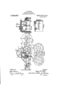
- Figure 1 is a plan of a ball hopper, such as is used at a minor register.
- Fig. 2 is a front view of a ticket issuing device with the front of a ball hopper showing.
- Fig. 3 is a reverse view of the ticket expeller and means for operating it.
- Fig. 4 is a side View of the ball controlling and ticket ejector mechanism.
- Fig. 5 is a section showing the non-automatic recording escapement.
- Fig. 6 shows the means of connecting the escapement with the disk mechanism.
- Fig. 7 is a back view of the registering mechanism with its mechanical stop device. Fig. 7 shows train of wheels operating registers.
- Fig. 8 is an end view of Fig. 7.
- Fig. 9 is.
- Fig. 10 is a general View of a complete layout showing the connection between parts.
- Fig. 11 is a detail view showing hand brake controlling grand total register.
- the pipe B (Figs. 2 and 4:) is severed at B to permit the ticket eXpellerB to revolve with the small miter wheel 13 when the handle B is rotated
- This pipe B is slotted on one side for the disk C on the handle shaft to revolve, while it is also slotted in front for the locking device to enter when no balls are in the tube.
- a stop D In front of the tube suspended from a small bracket C is a stop D which has at its lower end a tang D. This stop is kept out of the tube by the balls, but as soon as the last ball has been passed down by the slotted disk 0 it falls partly into the tube while the tang comes in front of a stud D and prevents the rotation of the handle, and consequently the issuing of another ticket until more balls are put in the hopper above.
- the disk C has a semicircular gap C in it, corresponding in size with half a ball so that if the handle can be turned round, a ball must [it in the gap and be passed downward.
- Contiguous to this pipe is the ticket box, with the hinged door E. open at the bottom with a bracket beneath, a space being left between for one ticket only to pass out at a time when ejected by the expeller
- a block of metal thicker than two tickets is used on the top of the tickets so that after the last is issued the expeller comes in contact with the metal and prevents further movement and the passing of a ball without a ticket.
- the registering device is shown in vFigs. 7, S, 9 and 10; in these figures the register has only units, tens and hundreds disks as P, but, for the grand total or major register, an extra disk is required to re ister thousands.
- Each disk P used to indicate units,tens, etc. is carried on a separate spindle P running in bearings I; this spindle also carries specially designed wheels such as Q which have semicircular gaps Q corresponding with the numerals, while the spaces between are curved to fit a disk having one toot-h only, which gears at regular intervals with the gap Q.
- Fig. 7 shows the arrangement of the train of wheels by means of which for every ten revolutions of the units wheel Q the tens wheel advances one and so on through the train.
- an eseapement controlling the movement consisting of a sprag J pivoted on the bed plate at J.
- This sprag J under normal conditions prevents the arm J and shattot the registering mechanism "from re volving; but. after the sprag has been released, and before the arm can come around again, the sprag J is replaced by the cam J and stops further registering.
- crank lever K which is connected through crank lever or lovers ii and wires K to the lever K, which latter is provided with a finger l and spring K.
- the arm K is arranged to strike the spra J as near the center J as possible so that only a short travel. is required and a high speed can be attained, while the sprag has the end extended for the cam J to operate against. 7
- lever ii may be pressed down as quickly possible and indications made on the register, until the last ball is through when the mechanism is instantly locked.
- the balls from the minor register after passing the star wheel. F travel along suitable ducts to the major register, which consists of the same mechanism as the minor register device (Fig. and. driven in the same way; but as it is required to be more rapid in its action having to register the total oi several registers, the sprag J and its attendant parts are omitted, and behind the star locking wheel I provide a drum N on the shaft F fitted with a brake P (Fig. 11) having a handle for the attendant to regulate the pressure on the drum, and consecniently the speed of the registering.
- FIG. 10 A general arrangement (Fig. 10) is shown to enable the connections to be traced, but in most cases the connections between the parts will be varied to suit the local conditions; but the working will be the same in all race work and may be described as follows:
- the mechanism being fixed up in suitable premises, with the requisite number of ticket issuing machines X and ticket windows X with their respective minor registers Y and a major register Z, tickets and balls being put in their respective places, a ticket is called for, the attendant at that window ro tates handle B and in doing so a ball slips into the gap 0 and passes down the pipe B (while a ticket is thrown out by the expeller B into its proper duct A, down that, through a slot A, onto a table A down the duct A (as in Fig.
- a registering mechanism the combination of disks having characters and adapted to move in seriatz'm; a plurality of balls adapted to actuate said disks; a tube for holding and guiding said balls; a rotatable disk projecting within said tube and adapted to control the passage of the balls there through; a shaft on which said disk is mounted; a rotatable arm connected to be actuated from said shaft; a ticket holder constructed to receive said rotatable arm whereby the tickets are ejected; and means for manually actuating said ball controlling disk and said ticket ejector, substantially as described.
- a registering mechanism the combination of disks having characters and adapted to move in seriatz'm; a plurality of balls adapted to actuate said disks; a tube in sections for holding and guiding said balls; a rotatable disk projecting within said tube and adapted to control the passage of the balls therethrough; a shaft on which said disk is mounted; a countershaft connected to be driven from the first-named shaft; an arm mounted on said coimtershaft and adapted to move between the tube sections; a ticket hopper constructed to receive said rotatable arm whereby the tickets are singly ejected therefrom; and manual means for actuating said ball controlling disk and said ticket ejector, substantially as described.
- a registering mechanism the combination of disks having characters and adapted to move in seriazfim; a plurality of balls adapted to actuate said disk; a tube for holding and guiding said balls; a rotatable disk projecting within said tube and adapted to control the passage of the balls therethrough; a manually actuating device for rotating said disk to control the passage of said balls; and a device associated with said tube and manually actuating device adapted to act as a stop for holding saidactuating device against movement when the balls are exhausted from said tube, substantially as described.
- a registering mechanism the combination of disks having characters and adapted to move in sem'atz'm; a plurality of balls adapted to actuate said disks; a tube for holding and guiding said balls; a rotatable disk projecting within said tube and adapted to control the passage of the balls therethrough; a manually actuating device for rotating said disk to control the passage of said balls; a vertically disposed and gravity actuated device mounted to project within said tube, and providing a stop for said manually actuating device, said stop normally held in inoperative position through engagement of said balls and adapted to move into operative position when said balls are exhausted; and a ticket ejecting device adapted to be actuated by said manually actuating device, substantially as described.
- a registering apparatus the combination of a plurality of hoppers; a sloping table associated therewith; a duct for said table; registering devices; means for operating said devices; means automatic for looking said last mentioned means comprising, a plate, a lug on said plate, a shaft, a starwheel on said shaft, said lug being adapted to engage said star-wheel, substantially as described.
- a registering mechanism the combination of disks having characters and adapted to move in seriatim; a plurality of balls adapted to actuate said disks; a tube for holding and guiding said balls; a rotatable disk projecting within said tube and adapted to control the passage of the balls therethrough a shaft on which said disk is mounted; a means for manually actuating said shaft; a ticket holding hopper having an open. bottom; a bracket located at said bottom and spaced from said hopper whereby to permit of removal of the tickets; a ticket ejecting device movable through said space for ejecting the tickets singly; and gearing connections between said disk shaft and said ticket ejecting device, substantially as described.
- a registering mechanism the combination of disks having characters and adapted to move in sci'z'azt'z'c'n; a plurality of balls; a tube within which said balls are adapted to have passage; a spur wheel mounted to project within said tube and be actuated by said balls; operative connections between said spur wheel and said disks; and an automatically actuated stop for said spur wheel; said step adapted to be held in inoperative position through engagement with the balls in the tube but releasable When the balls are xhausted therefrom, substantially as described.
Landscapes
- Engineering & Computer Science (AREA)
- Human Computer Interaction (AREA)
- Health & Medical Sciences (AREA)
- General Health & Medical Sciences (AREA)
- Physical Education & Sports Medicine (AREA)
- Pinball Game Machines (AREA)
Description
H. HODSDON.
ENUMERATING MACHINE.
APPLICATION FILED SEPT. 25, 1911.
1,034,239. Patented July .30, 1912.
4 SHEETS-SHEET 1.
I l I 1 l I A M A AK A A I A A .k
[7 amp A 17' shape [7 .iope FIG- A A A a a A A M A A A N A r- N h A.
Fmz F'|c..5 FIG. 4
Witnwey Inventor 4 I w 75 011 145 W54; IQ w y f flttorneyo COLUMBIA PLANOGRAPII 50.. WASHINGTON. D c- H. HODSDON.
ENUMERATING MACHINE.
APPLICATION FILED SEPT. 25, 1911.
4 SHEE TSSH'EET 2.
FIQG
Patented July 30, 1912.
COLUMBIA PLANOGRAPH COHWASHINGTONI n. c.
Witnesses H; HODSDON. ENUMBRATING MACHINE.
' APPLICATION FILED SEPT. 25, 1911. 1,034,239. Patented July so, 1912.
4 SHEETS-SHEET 3.
FIG-.8
Inventor i 2 ,44, f-d/o ua I M 4/ fittm'nggs.
H. HODSDON. ENUMERATING MACHINE.
APPLICATION FILED snr'r. 25, 1911.
Patented July 30,1912.
4 SHEETS-SHEET 4,.
Witnesses Inventor 'r fittonwy s.
COLUMBIA PLANOGRAPH c0.,wAsH|Na TON, D.c.
UNTTED $TATE$ PATENT UFFTCE.
HENRY HODSDON, OF BRISBANE, QUEENSLAND, AUSTRALIA, ASSIGNOR TO THE HODS- DON PATENT TOTALISEB. AND ENUMERATING MACHINES COMPANY LIMITED, OF
BRISBANE, AUSTRALIA.
To all whom it may concern:
Be it known that l, HENRY HonsnoN, a subject of the King of Great Britain, residing at Tattersalls Estate, Eagle Farm, Brisbane, in the State of Queensland, Commonwealth of Australia, carpenter, have in vented certain new and useful Improvements in and Relating to Enumerating-Machines; and I do hereby declare the following to be a full, clear, and eXact description of the invention, such as will enable others skilled in the art to which it appertains to make and use the same.
My invention refers to improvements in and relating to indicating or registering machines of the class known in some countries as totalizers and used principally in connection with horse races.
Mly invention provides a simple machine that is rapid in registering and accurate in its additions and owing to specially designed locking arrangements, if a ticket is issued at any one window an indication of same must be made on the individual or minor register and also on the major register or grand total.
The machine is installed in a suitable building with the desired number of Windows where tickets can be purchased; at each window are the requisite number of ticket issuing devices, each holding the tickets on a different number or horse, and also provided with a suitable number of polished metal balls. Over these windows or elsewhere, are placed the minor registers to indicate the number of tickets issued on each horse, while the grand total indicates all tickets issued.
On a ticket being called for, the attendant turns the handle of the proper ticket issuing device; this eXpels one ticket and releases one ball. The former is handed to the purchaser and the latter goes along a suitable duct to the minor register where an attendant, allows it to register one; it then passes on to the grand total and is there also registered after which it is available for further distribution.
In the event of the supply of tickets or balls failing, in either case a positive lock intervenes and prevents one being issued without the other.
The register devices I use, have a series of disks with the numerals painted on the face,
Specification of Letters Patent.
Application filed September 25, 1911.
Patented July 30,1912.
Serial No. 651,195.
and the different spindles carrying the units, tens, etc., are arranged so that they can readily be disengaged from their gears and put to zero.
I prefer to drive each registering device by means of a cord wound upon a barrel and carrying a weight. In order however that my invent-ion may be clearly understood I will now describe it with the aid of the accompanying drawings.
Figure 1 is a plan of a ball hopper, such as is used at a minor register. Fig. 2 is a front view of a ticket issuing device with the front of a ball hopper showing. Fig. 3 is a reverse view of the ticket expeller and means for operating it. Fig. 4 is a side View of the ball controlling and ticket ejector mechanism. Fig. 5 is a section showing the non-automatic recording escapement. Fig. 6 shows the means of connecting the escapement with the disk mechanism. Fig. 7 is a back view of the registering mechanism with its mechanical stop device. Fig. 7 shows train of wheels operating registers.
Fig. 8 is an end view of Fig. 7. Fig. 9 is.
a detail view showing the no ball stop. Fig. 10 is a general View of a complete layout showing the connection between parts. Fig. 11 is a detail view showing hand brake controlling grand total register.
Now beginning at the ball hopper A, A, are ducts leading with a slope from the ball issuing station and discharging through the slots A into the hoppers of their respective registers; the balls fall onto a table having a slope A of 17 from which they roll off into the duct A (at right angles to the slope) leading into the pipe B at the ticket issuing device. When the pipe and duct are full, the balls pile upon each other but owing to the angles do not stick anywhere and move on readily when the machine is operated.
The pipe B (Figs. 2 and 4:) is severed at B to permit the ticket eXpellerB to revolve with the small miter wheel 13 when the handle B is rotated This pipe B is slotted on one side for the disk C on the handle shaft to revolve, while it is also slotted in front for the locking device to enter when no balls are in the tube.
In front of the tube suspended from a small bracket C is a stop D which has at its lower end a tang D. This stop is kept out of the tube by the balls, but as soon as the last ball has been passed down by the slotted disk 0 it falls partly into the tube while the tang comes in front of a stud D and prevents the rotation of the handle, and consequently the issuing of another ticket until more balls are put in the hopper above.
The disk C has a semicircular gap C in it, corresponding in size with half a ball so that if the handle can be turned round, a ball must [it in the gap and be passed downward. Contiguous to this pipe is the ticket box, with the hinged door E. open at the bottom with a bracket beneath, a space being left between for one ticket only to pass out at a time when ejected by the expeller A block of metal thicker than two tickets is used on the top of the tickets so that after the last is issued the expeller comes in contact with the metal and prevents further movement and the passing of a ball without a ticket. After a ball has been passed by rotating the handle 13", it falls down the pipe B into a ductsuch as A, and on to its respective hopper A, into the pipe 13 (Figs. 1 and 5) where its progress is blocked by a star wheel F geared to the register, through the shafts F and miter wheels F The pipe B has a slot at the back for the stop G to fall in when no balls are in it; this stop G has a tang G on its lower end that engages the teeth of a star wheel. G coinciding with the star wheel ll so that immediately the last ball has passed the star wheel F,the register is locked, and nothing can be added to the total until another ticket has been issued and a ball passed. on its way.
The registering device is shown in vFigs. 7, S, 9 and 10; in these figures the register has only units, tens and hundreds disks as P, but, for the grand total or major register, an extra disk is required to re ister thousands. Each disk P used to indicate units,tens, etc.,is carried on a separate spindle P running in bearings I; this spindle also carries specially designed wheels such as Q which have semicircular gaps Q corresponding with the numerals, while the spaces between are curved to fit a disk having one toot-h only, which gears at regular intervals with the gap Q.
Fig. 7 shows the arrangement of the train of wheels by means of which for every ten revolutions of the units wheel Q the tens wheel advances one and so on through the train.
At the end of the frame carrying the spindle P is an eseapement controlling the movement consisting of a sprag J pivoted on the bed plate at J. This sprag J under normal conditions prevents the arm J and shattot the registering mechanism "from re volving; but. after the sprag has been released, and before the arm can come around again, the sprag J is replaced by the cam J and stops further registering.
The sprag is displaced by an attendant operating the crank lever K, which is connected through crank lever or lovers ii and wires K to the lever K, which latter is provided with a finger l and spring K.
it will be understood that no numbers are added to the register until the attendant presses down the lever K thereby causing the finger K" to knock out the sprag J so all owing the arm to at once rotate by means of the gearing and power supplied by the cord ll, which is normally under the tension of a weight (not shown). No sooner has the arm J started to revolve than the cam J repla .08 the sprag J, and checks further movement.
The arm K is arranged to strike the spra J as near the center J as possible so that only a short travel. is required and a high speed can be attained, while the sprag has the end extended for the cam J to operate against. 7
1n the event of there being no ball in the pipe 13 the stop G will be in the slot and the tang G holding the star wheel and through the. gearing, the whole of the register mocha menu.
It balls are in the tube B the lever ii may be pressed down as quickly possible and indications made on the register, until the last ball is through when the mechanism is instantly locked.
The balls from the minor register after passing the star wheel. F, travel along suitable ducts to the major register, which consists of the same mechanism as the minor register device (Fig. and. driven in the same way; but as it is required to be more rapid in its action having to register the total oi several registers, the sprag J and its attendant parts are omitted, and behind the star locking wheel I provide a drum N on the shaft F fitted with a brake P (Fig. 11) having a handle for the attendant to regulate the pressure on the drum, and consecniently the speed of the registering.
The operation is the same as that described in the minor register; atter a ball leaves one of the minor registers, it rolls along suitable ducts to the major register receiver, which is made to receive from all the minor registers; and the attendant, as he finds the balls coming down, releases the brake P, and the mechanism being free to revolve by reason of the driving weight on the cord H, does so as long as there are balls to pass around the star wheel in, the brake being used to prevent too great a speed being attained and reduce same as the balls are reduced in number. By this means a very large number can be registered on the grand or major total in a very short space of time.
A general arrangement (Fig. 10) is shown to enable the connections to be traced, but in most cases the connections between the parts will be varied to suit the local conditions; but the working will be the same in all race work and may be described as follows: The mechanism. being fixed up in suitable premises, with the requisite number of ticket issuing machines X and ticket windows X with their respective minor registers Y and a major register Z, tickets and balls being put in their respective places, a ticket is called for, the attendant at that window ro tates handle B and in doing so a ball slips into the gap 0 and passes down the pipe B (while a ticket is thrown out by the expeller B into its proper duct A, down that, through a slot A, onto a table A down the duct A (as in Fig. 1) into the pipe B feeding the minor register mechanism, from whence it is released by the attendant pressing the lever K, and so removing the sprag J, allowing the mechanism to register one number before the cam J 3 replaces the sprag and stops the mechanism. If the lever K be lightly pressed down the sprag is so quickly released and detained that the registering is extremely rapid so long as there are balls to pass. From the minor register the balls pass onto the major register where the attendant lets them pass through as before described, after which the balls are ready for further distribution in any of the hoppers requiring replenishing.
Having now particularly described and ascertained the nature of my said invention, and in what manner the same is to be performed, I declare that what I claim is 1. In a registering mechanism, the combination of disks having characters and adapted to move in seriatm; a plurality of balls adapted to actuate said disks; a tube for holding and guiding said balls; a rotatable diskprojecting within said tube and adapt ed to control the passage of the balls therethrough; a device for manually actuating said rotatable disk; and a ticket ejecting device connected to be actuated by said manually actuating device, substantially as described.
2. In a registering mechanism, the combination of disks having characters and adapted to move in seriatz'm; a plurality of balls adapted to actuate said disks; a tube for holding and guiding said balls; a rotatable disk projecting within said tube and adapted to control the passage of the balls there through; a shaft on which said disk is mounted; a rotatable arm connected to be actuated from said shaft; a ticket holder constructed to receive said rotatable arm whereby the tickets are ejected; and means for manually actuating said ball controlling disk and said ticket ejector, substantially as described.
3. In a registering mechanism, the combination of disks having characters and adapted to move in seriatz'm; a plurality of balls adapted to actuate said disks; a tube in sections for holding and guiding said balls; a rotatable disk projecting within said tube and adapted to control the passage of the balls therethrough; a shaft on which said disk is mounted; a countershaft connected to be driven from the first-named shaft; an arm mounted on said coimtershaft and adapted to move between the tube sections; a ticket hopper constructed to receive said rotatable arm whereby the tickets are singly ejected therefrom; and manual means for actuating said ball controlling disk and said ticket ejector, substantially as described.
4. In a registering mechanism, the combination of disks having characters and adapted to move in seriazfim; a plurality of balls adapted to actuate said disk; a tube for holding and guiding said balls; a rotatable disk projecting within said tube and adapted to control the passage of the balls therethrough; a manually actuating device for rotating said disk to control the passage of said balls; and a device associated with said tube and manually actuating device adapted to act as a stop for holding saidactuating device against movement when the balls are exhausted from said tube, substantially as described.
5. In a registering mechanism, the combination of disks having characters and adapted to move in sem'atz'm; a plurality of balls adapted to actuate said disks; a tube for holding and guiding said balls; a rotatable disk projecting within said tube and adapted to control the passage of the balls therethrough; a manually actuating device for rotating said disk to control the passage of said balls; a vertically disposed and gravity actuated device mounted to project within said tube, and providing a stop for said manually actuating device, said stop normally held in inoperative position through engagement of said balls and adapted to move into operative position when said balls are exhausted; and a ticket ejecting device adapted to be actuated by said manually actuating device, substantially as described.
6. In a registering apparatus, the combination of a plurality of hoppers; a sloping table associated therewith; a duct for said table; registering devices; means for operating said devices; means automatic for looking said last mentioned means comprising, a plate, a lug on said plate, a shaft, a starwheel on said shaft, said lug being adapted to engage said star-wheel, substantially as described.
7. In a registering mechanism, the combination of disks having characters and adapted to move in seriatim; a plurality of balls adapted to actuate said disks; a tube for holding and guiding said balls; a rotatable disk projecting within said tube and adapted to control the passage of the balls therethrough a shaft on which said disk is mounted; a means for manually actuating said shaft; a ticket holding hopper having an open. bottom; a bracket located at said bottom and spaced from said hopper whereby to permit of removal of the tickets; a ticket ejecting device movable through said space for ejecting the tickets singly; and gearing connections between said disk shaft and said ticket ejecting device, substantially as described.
S. In a registering mechanism, the combination of disks having characters and adapted to move in sci'z'azt'z'c'n; a plurality of balls; a tube within which said balls are adapted to have passage; a spur wheel mounted to project within said tube and be actuated by said balls; operative connections between said spur wheel and said disks; and an automatically actuated stop for said spur wheel; said step adapted to be held in inoperative position through engagement with the balls in the tube but releasable When the balls are xhausted therefrom, substantially as described.
9. in a registering mechanism, the combination of disks haying characters and adapted to more in scrimfim; a plurality of balls adapted to actuate said disks; a tube for holding and guiding said balls; a spur wheel projecting within said tube and operable through engagen'ient with said balls; operative connections between said spur wheel and said disks; a vertically disposed stop projecting within said tube and adapted to engage with and be held in inoperative position through engagement with the balls in the tube and to be released therefrom when the balls are exhausted from the tube; and a ma-i'iually actuated means for controlling said step, substantially described.
In testimony whereof, I affix my signature, in presence of two witnesses.
HENRY HODSDON. lVitnesses A. Hancock, A. BISHOP.
Copies of this patent may be obtained for five cents each, by addressing the Commissioner of Patents,
Washington, D. S.
Priority Applications (1)
| Application Number | Priority Date | Filing Date | Title |
|---|---|---|---|
| US65119511A US1034239A (en) | 1911-09-25 | 1911-09-25 | Enumerating-machine. |
Applications Claiming Priority (1)
| Application Number | Priority Date | Filing Date | Title |
|---|---|---|---|
| US65119511A US1034239A (en) | 1911-09-25 | 1911-09-25 | Enumerating-machine. |
Publications (1)
| Publication Number | Publication Date |
|---|---|
| US1034239A true US1034239A (en) | 1912-07-30 |
Family
ID=3102520
Family Applications (1)
| Application Number | Title | Priority Date | Filing Date |
|---|---|---|---|
| US65119511A Expired - Lifetime US1034239A (en) | 1911-09-25 | 1911-09-25 | Enumerating-machine. |
Country Status (1)
| Country | Link |
|---|---|
| US (1) | US1034239A (en) |
-
1911
- 1911-09-25 US US65119511A patent/US1034239A/en not_active Expired - Lifetime
Similar Documents
| Publication | Publication Date | Title |
|---|---|---|
| US1893828A (en) | Machine for separating and counting coins | |
| US1096172A (en) | Coin-counting mechanism. | |
| US1268669A (en) | Fare-register. | |
| US2524387A (en) | Key controlled type selection | |
| US1479459A (en) | Counting machine | |
| US490823A (en) | Liquid measuring and recording apparatus | |
| US643515A (en) | Machine for keeping count of games of dominoes. | |
| US2195770A (en) | A doebeli | |
| US1386709A (en) | Assig-itob to ttstited atjtggsaphic | |
| US1943025A (en) | Ticket issuing and change giving machine | |
| US602185A (en) | Vending-machine | |
| US1573955A (en) | Pencil-vending machine | |
| US2057651A (en) | Register device for game apparatus | |
| US600259A (en) | detjbner | |
| US385265A (en) | Cash indicator | |
| US964986A (en) | Voting-machine. | |
| US824794A (en) | Coin-counting machine. | |
| US878787A (en) | Coin freed or operated machine for vending postage-stamps, tickets, &c. | |
| US603111A (en) | mason | |
| US965352A (en) | Independent-ballot-voting mechanism. | |
| US895613A (en) | Automatic ticket dating and delivering apparatus. | |
| US959482A (en) | Card-vending machine. | |
| US1054994A (en) | Fortune telling and recording machine. | |
| US2019268A (en) | Machine for the delivery of tokens | |
| US935062A (en) | Stamp-vending machine. |