US10334130B2 - Image forming apparatus, image forming system, and position adjustment method - Google Patents
Image forming apparatus, image forming system, and position adjustment method Download PDFInfo
- Publication number
- US10334130B2 US10334130B2 US15/921,616 US201815921616A US10334130B2 US 10334130 B2 US10334130 B2 US 10334130B2 US 201815921616 A US201815921616 A US 201815921616A US 10334130 B2 US10334130 B2 US 10334130B2
- Authority
- US
- United States
- Prior art keywords
- liquid discharge
- image
- sensor
- head units
- conveyed object
- Prior art date
- Legal status (The legal status is an assumption and is not a legal conclusion. Google has not performed a legal analysis and makes no representation as to the accuracy of the status listed.)
- Expired - Fee Related
Links
Images


Classifications
-
- H—ELECTRICITY
- H04—ELECTRIC COMMUNICATION TECHNIQUE
- H04N—PICTORIAL COMMUNICATION, e.g. TELEVISION
- H04N1/00—Scanning, transmission or reproduction of documents or the like, e.g. facsimile transmission; Details thereof
- H04N1/00567—Handling of original or reproduction media, e.g. cutting, separating, stacking
- H04N1/0066—Aligning or positioning related to handling
-
- B—PERFORMING OPERATIONS; TRANSPORTING
- B41—PRINTING; LINING MACHINES; TYPEWRITERS; STAMPS
- B41J—TYPEWRITERS; SELECTIVE PRINTING MECHANISMS, i.e. MECHANISMS PRINTING OTHERWISE THAN FROM A FORME; CORRECTION OF TYPOGRAPHICAL ERRORS
- B41J2/00—Typewriters or selective printing mechanisms characterised by the printing or marking process for which they are designed
- B41J2/005—Typewriters or selective printing mechanisms characterised by the printing or marking process for which they are designed characterised by bringing liquid or particles selectively into contact with a printing material
- B41J2/01—Ink jet
- B41J2/21—Ink jet for multi-colour printing
- B41J2/2132—Print quality control characterised by dot disposition, e.g. for reducing white stripes or banding
- B41J2/2135—Alignment of dots
-
- B—PERFORMING OPERATIONS; TRANSPORTING
- B41—PRINTING; LINING MACHINES; TYPEWRITERS; STAMPS
- B41J—TYPEWRITERS; SELECTIVE PRINTING MECHANISMS, i.e. MECHANISMS PRINTING OTHERWISE THAN FROM A FORME; CORRECTION OF TYPOGRAPHICAL ERRORS
- B41J2/00—Typewriters or selective printing mechanisms characterised by the printing or marking process for which they are designed
- B41J2/005—Typewriters or selective printing mechanisms characterised by the printing or marking process for which they are designed characterised by bringing liquid or particles selectively into contact with a printing material
- B41J2/01—Ink jet
- B41J2/21—Ink jet for multi-colour printing
- B41J2/2132—Print quality control characterised by dot disposition, e.g. for reducing white stripes or banding
- B41J2/2146—Print quality control characterised by dot disposition, e.g. for reducing white stripes or banding for line print heads
-
- B—PERFORMING OPERATIONS; TRANSPORTING
- B41—PRINTING; LINING MACHINES; TYPEWRITERS; STAMPS
- B41J—TYPEWRITERS; SELECTIVE PRINTING MECHANISMS, i.e. MECHANISMS PRINTING OTHERWISE THAN FROM A FORME; CORRECTION OF TYPOGRAPHICAL ERRORS
- B41J25/00—Actions or mechanisms not otherwise provided for
- B41J25/001—Mechanisms for bodily moving print heads or carriages parallel to the paper surface
-
- H—ELECTRICITY
- H04—ELECTRIC COMMUNICATION TECHNIQUE
- H04N—PICTORIAL COMMUNICATION, e.g. TELEVISION
- H04N1/00—Scanning, transmission or reproduction of documents or the like, e.g. facsimile transmission; Details thereof
- H04N1/00002—Diagnosis, testing or measuring; Detecting, analysing or monitoring not otherwise provided for
- H04N1/00005—Diagnosis, testing or measuring; Detecting, analysing or monitoring not otherwise provided for relating to image data
-
- H—ELECTRICITY
- H04—ELECTRIC COMMUNICATION TECHNIQUE
- H04N—PICTORIAL COMMUNICATION, e.g. TELEVISION
- H04N1/00—Scanning, transmission or reproduction of documents or the like, e.g. facsimile transmission; Details thereof
- H04N1/04—Scanning arrangements, i.e. arrangements for the displacement of active reading or reproducing elements relative to the original or reproducing medium, or vice versa
- H04N1/047—Detection, control or error compensation of scanning velocity or position
-
- H—ELECTRICITY
- H04—ELECTRIC COMMUNICATION TECHNIQUE
- H04N—PICTORIAL COMMUNICATION, e.g. TELEVISION
- H04N2201/00—Indexing scheme relating to scanning, transmission or reproduction of documents or the like, and to details thereof
- H04N2201/04—Scanning arrangements
- H04N2201/047—Detection, control or error compensation of scanning velocity or position
- H04N2201/04701—Detection of scanning velocity or position
- H04N2201/04703—Detection of scanning velocity or position using the scanning elements as detectors, e.g. by performing a prescan
-
- H—ELECTRICITY
- H04—ELECTRIC COMMUNICATION TECHNIQUE
- H04N—PICTORIAL COMMUNICATION, e.g. TELEVISION
- H04N2201/00—Indexing scheme relating to scanning, transmission or reproduction of documents or the like, and to details thereof
- H04N2201/04—Scanning arrangements
- H04N2201/047—Detection, control or error compensation of scanning velocity or position
- H04N2201/04701—Detection of scanning velocity or position
- H04N2201/0471—Detection of scanning velocity or position using dedicated detectors
-
- H—ELECTRICITY
- H04—ELECTRIC COMMUNICATION TECHNIQUE
- H04N—PICTORIAL COMMUNICATION, e.g. TELEVISION
- H04N2201/00—Indexing scheme relating to scanning, transmission or reproduction of documents or the like, and to details thereof
- H04N2201/04—Scanning arrangements
- H04N2201/047—Detection, control or error compensation of scanning velocity or position
- H04N2201/04701—Detection of scanning velocity or position
- H04N2201/04715—Detection of scanning velocity or position by detecting marks or the like, e.g. slits
Definitions
- This disclosure relates to an image forming apparatus, an image forming system, and a position adjustment method.
- image forming methods that include discharging ink from a print head (so-called inkjet method).
- image forming methods include, for example, adjusting the position of the print head relative to the recording media.
- the print head is adjusted based on results of detection by a sensor detecting a position of a recording medium (e.g., a web) conveyed through a print system.
- a recording medium e.g., a web
- An embodiment of this disclosure provides an image forming apparatus that includes a conveyor to convey a conveyed object in a conveyance direction, a plurality of head units to perform image formation on the conveyed object, a displacement sensor disposed downstream from the plurality of head units to detect a position adjustment image on the conveyed object, formed by the plurality of head units, and at least one processor configured to adjust an image formation position of at least one of the plurality of head units in an orthogonal direction to the conveyance direction based on a detection result generated by the displacement sensor.
- the processor is configured to adjust the image formation position to an adjusted position.
- the image forming apparatus further includes a surface sensor to obtain surface data of the conveyed object at a position corresponding to the at least one of the plurality of head units, and the processor is further configured to adjust the adjusted position in the orthogonal direction based on the surface data obtained by the surface sensor.
- an image forming system includes a plurality of image forming apparatuses each of which includes the above-described conveyor, the above-described displacement sensor, the above-described processor, and the above-described surface sensor.
- Another embodiment provides a method for adjusting a position of image formation on a conveyed object.
- the method includes detecting a position adjustment image, formed by the plurality of head units, on the conveyed object at a position downstream from the plurality of head units; adjusting, to an adjusted position, an image formation position of at least one of the plurality of head units in an orthogonal direction to a conveyance direction in which the conveyed object is conveyed, based on a result of detection of the position adjustment image; obtaining surface data of the conveyed object at a position corresponding to the at least one of the plurality of head units; and adjusting the adjusted position in the orthogonal direction based on the surface data obtained.
- FIG. 1 is a schematic view of a liquid discharge apparatus according to an embodiment
- FIG. 2 is a schematic view illustrating a general structure of the liquid discharge apparatus illustrated in FIG. 1 ;
- FIGS. 3A and 3B are schematic views illustrating an external shape of a liquid discharge head unit according to an embodiment
- FIG. 4 illustrates an example of displacement of a web
- FIG. 5 is an illustration for calculating the amount of displacement according an embodiment
- FIG. 6 is another illustration for calculating the amount of displacement according an embodiment
- FIG. 7 is a schematic illustration of position adjustment of the liquid discharge head unit according to an embodiment
- FIG. 8 is a schematic diagram of an example mechanism to move the liquid discharge head unit of the liquid discharge apparatus, according to an embodiment
- FIG. 9 is a schematic block diagram of a hardware configuration of a controller according to an embodiment.
- FIG. 10 is a block diagram of a hardware configuration of a data management device of the controller illustrated in FIG. 9 ;
- FIG. 11 is a block diagram of a hardware configuration of an image output device of the controller illustrated in FIG. 9 ;
- FIG. 12 is a flowchart of position adjustment performed by the liquid discharge apparatus; according to an embodiment
- FIG. 13 is a schematic functional block diagram of the liquid discharge apparatus, according to an embodiment
- FIG. 14 is a schematic block diagram illustrating a hardware configuration to implement a surface detecting unit according to an embodiment
- FIG. 15 is an external view of a surface sensor device according to an embodiment
- FIG. 16 is a schematic functional block diagram of a configuration incorporating the surface detecting unit according to an embodiment
- FIG. 17 is a diagram of a method of correlation operation according to an embodiment
- FIG. 18 is a graph for understanding of a peak position searched in the correlation operation illustrated in FIG. 17 ;
- FIG. 19 is a diagram of example results of the correlation operation illustrated in FIG. 17 ;
- FIG. 20 is a flowchart of surface detection and position adjustment of a liquid discharge head unit during image formation, according to a variation
- FIG. 21 is a timing chart of calculation of the amount of displacement of a conveyed object, according to an embodiment
- FIG. 22 is a schematic view of a liquid discharge apparatus according to a variation.
- FIG. 23 is a schematic view of a liquid discharge apparatus according to another variation.
- a head of an image forming apparatus is a liquid discharge head unit to discharge liquid.
- FIG. 1 is a schematic view of an example of an image forming apparatus according to an embodiment.
- the image forming apparatus is a liquid discharge apparatus having a structure illustrated in FIG. 1 .
- the liquid discharge apparatus discharges recording liquid such as aqueous ink or oil-based ink.
- a liquid discharge apparatus 110 is described below as an example of the image forming apparatus according to the present embodiment.
- the liquid discharge apparatus 110 illustrated in FIG. 1 conveys a conveyed object such as a web 120 .
- the liquid discharge apparatus 110 includes a roller 130 and the like to convey the web 120 , and discharges liquid onto the web 120 to form an image thereon.
- the web 120 is considered as a recording medium.
- the web 120 is a so-called continuous sheet. That is, the web 120 is, for example, a rolled sheet to be reeled.
- the liquid discharge apparatus 110 is a so-called production printer. The description below concerns an example in which the roller 130 adjusts the tension of the web 120 and conveys the web 120 in a conveyance direction 10 .
- the liquid discharge apparatus 110 is an inkjet printer to discharge four color inks, namely, black (K), cyan (C), magenta (M), and yellow (Y) inks, to form an image on the web 120 .
- FIG. 2 is a schematic view illustrating a general structure of the liquid discharge apparatus 110 .
- the liquid discharge apparatus 110 includes four liquid discharge head units 210 ( 210 Y, 210 M, 210 C, and 210 K) to discharge the four inks, respectively.
- the liquid discharge apparatus 110 includes a displacement sensor PSEN disposed downstream from the extreme downstream liquid discharge head unit 210 in the conveyance direction 10 .
- Each liquid discharge head unit 210 discharges the ink onto the web 120 conveyed in the conveyance direction 10 .
- the liquid discharge apparatus 110 includes two pairs of nip rollers, a roller 230 , and the like, to convey the web 120 .
- One of the two pairs of nip rollers is a first nip roller pair NR 1 disposed upstream from the liquid discharge head units 210 in the conveyance direction 10 .
- the other is a second nip roller pair NR 2 disposed downstream from the first nip roller pair NR 1 and the liquid discharge head units 210 in the conveyance direction 10 .
- Each nip roller pair rotates while nipping the conveyed object, such as the web 120 , as illustrated in FIG. 2 .
- the nip roller pairs and the roller 230 together serve as a conveyor to convey the conveyed object (e.g., the web 120 ) in a predetermined direction.
- the recording medium such as the web 120 is preferably a long sheet. Specifically, the recording medium is preferably longer than the distance between the first nip roller pair NR 1 and the second nip roller pair NR 2 .
- the recording medium is not limited to webs.
- the recording medium can be a folded sheet (so-called fanfold paper or Z-fold paper).
- the liquid discharge head units 210 are arranged in the order of black, cyan, magenta, and yellow in the conveyance direction 10 .
- the liquid discharge head unit 210 K for black is disposed extreme upstream
- the liquid discharge head unit 210 C for cyan is disposed next to the liquid discharge head unit 210 K.
- the liquid discharge head unit 210 M for magenta is disposed next to the liquid discharge head unit 210 C for cyan
- the liquid discharge head unit 210 Y for yellow is disposed extreme downstream in the conveyance direction 10 .
- Each liquid discharge head unit 210 discharges the ink to a predetermined position on the web 120 , according to image data.
- the position at which an image is formed with the ink (hereinafter “landing position”) is almost identical to the position at which the ink is discharged from the liquid discharge head unit 210 .
- the ink landing position is, for example, directly below the liquid discharge head unit 210 .
- the position at which an image is formed (i.e., an operation position) by the liquid discharge head unit 210 is the landing position.
- black ink is discharged to the ink landing position of the liquid discharge head unit 210 K (hereinafter “black landing position PK”).
- cyan ink is discharged to the ink landing position of the liquid discharge head unit 210 C (hereinafter “cyan landing position PC”).
- Magenta ink is discharged to the ink landing position of the liquid discharge head unit 210 M (hereinafter “magenta landing position PM”).
- Yellow ink is discharged to the ink landing position of the liquid discharge head unit 210 Y (hereinafter “yellow landing position PY”).
- a controller 520 operably connected to the liquid discharge head units 210 controls the respective timings of ink discharge of the liquid discharge head units 210 and actuators ACT illustrated in FIG. 8 , to move the liquid discharge head units 210 .
- the timing control and the actuator control is performed by two or more controllers (or control circuits).
- the actuators ACT are to be described later.
- each liquid discharge head unit 210 is provided with a plurality of rollers.
- the liquid discharge apparatus 110 includes the rollers respectively disposed upstream and downstream from each liquid discharge head unit 210 .
- each liquid discharge head unit 210 is provided with one roller (i.e., a first roller) to support the web 120 , disposed upstream from the ink landing position and another roller (i.e., a second roller) to support the web 120 , disposed downstream from the ink landing position, in the conveyance passage along which the web 120 is conveyed.
- a first roller to support the web 120 , disposed upstream from the ink landing position
- another roller i.e., a second roller
- Disposing the first roller and the second roller for each ink landing position can suppress fluttering of the recording medium conveyed.
- the first roller and the second roller are driven rollers. Alternatively, the first roller and the second roller may be driven by a motor or the like.
- first and second supports that are not rotatable to support the conveyed object can be used.
- each of the first and second supports can be a pipe or a shaft having a round cross section.
- each of the first and second supports can be a curved plate having an arc-shaped face to contact the conveyed object.
- the first and second supporters are rollers.
- a first roller CR 1 K is disposed upstream from the black ink landing position PK in the conveyance direction 10 in which the web 120 is conveyed.
- a second roller CR 2 K is disposed downstream from the black ink landing position PK in the conveyance direction 10 .
- a first roller CR 1 C and a second roller CR 2 C are disposed upstream and downstream from the liquid discharge head unit 210 C for cyan, respectively.
- a first roller CR 1 M and a second roller CR 2 M are disposed upstream and downstream from the liquid discharge head unit 210 M, respectively.
- a first roller CR 1 Y and a second roller CR 2 Y are disposed upstream and downstream from the liquid discharge head unit 210 Y, respectively.
- the liquid discharge apparatus 110 includes a surface sensor device to implement, at least, a part of a surface detecting unit 110 F 10 (illustrated in FIG. 14 ).
- a surface sensor device to implement, at least, a part of a surface detecting unit 110 F 10 (illustrated in FIG. 14 ).
- the number of surface sensor devices can be five or greater than five.
- the surface sensor device provided for the liquid discharge head unit 210 K for black is referred to as “sensor device SENK”.
- the surface sensor device provided for the liquid discharge head unit 210 C for cyan is referred to as “sensor device SENC”.
- the surface sensor device provided for the liquid discharge head unit 210 M for magenta is referred to as “sensor device SENM”.
- the surface sensor device provided for the liquid discharge head unit 210 Y for yellow is referred to as “sensor device SENY”.
- the sensor devices SENK, SENC, SENM, and SENY may be collectively referred to as “sensor devices SEN” or “surface sensor devices”.
- location of surface sensor device means the position where the detection is performed. Accordingly, it is not necessary that all components relating to the detection are disposed at the “location of surface sensor device”. In one embodiment, some of the components are coupled to the optical sensor via a cable and disposed away therefrom.
- references “SENK, SENC, SENM, and SENY” are given at respective example locations of surface sensor devices in the liquid discharge apparatus 110 .
- FIG. 3A is a schematic plan view of one of the four liquid discharge head units 210 K, 210 C, 210 M, and 210 Y of the liquid discharge apparatus 110 .
- each liquid discharge head unit 210 is a line head unit. That is, the liquid discharge apparatus 110 includes the four liquid discharge head units 210 K, 210 C, 210 M, and 210 Y arranged in the order of black, cyan, magenta, and yellow in the conveyance direction 10 .
- the liquid discharge head unit 210 K includes four heads 210 K- 1 , 210 K- 2 , 210 K- 3 , and 210 K- 4 arranged in a staggered manner in the orthogonal direction 20 .
- the liquid discharge apparatus 110 can form an image across the image formation area on the web 120 in the width direction orthogonal to the conveyance direction 10 .
- the liquid discharge head units 210 C, 210 M, and 210 Y can be similar in structure to the liquid discharge head unit 210 K, and the descriptions of other color liquid discharge head units are omitted to avoid redundancy.
- liquid discharge head unit including four heads
- a liquid discharge head unit including a single head can be used.
- the liquid discharge apparatus 110 includes a device, which in the illustrated example is the displacement sensor PSEN, to detect the position of the image formed on the web 120 , with the liquid discharged by the liquid discharge head unit 210 .
- a device which in the illustrated example is the displacement sensor PSEN, to detect the position of the image formed on the web 120 , with the liquid discharged by the liquid discharge head unit 210 .
- the displacement sensor PSEN can be a contactless sensor to detect the position where the head unit has formed an image.
- the displacement sensor PSEN is a laser displacement sensor, a complementary metal oxide semiconductor (CMOS) camera, a charge-coupled device (CCD) camera, an optical sensor, a two-dimensional sensor, an area sensor, or a combination thereof.
- CMOS complementary metal oxide semiconductor
- CCD charge-coupled device
- the displacement sensor PSEN can be hardware similar to the hardware to implement the surface detecting unit 110 F 10 illustrated in FIG. 14 .
- the amount of displacement is represented by the difference in the positions detected by the displacement sensor PSEN. Calculation of the amount of displacement is described below.
- displacement of the conveyed object arises as follows.
- FIG. 4 illustrates an example of displacement of a web.
- the web being conveyed by a conveyance roller RLL e.g., the first roller or the second roller
- RLL conveyance roller
- the web is set to be parallel to the conveyance direction 10 without skew as indicated by bold lines.
- the web being in this state is referred to as a no-skew web 120 A.
- the amount of displacement is almost zero.
- the web may be looped askew around the conveyance roller RLL to be skewed as indicated by broken lines.
- the web being in this state is referred to as a skewed web 120 B.
- the skewed web 120 B is at an angle to the conveyance direction 10 compared with the no-skew web 120 A.
- the skewed web 120 B is an example of the web having displacement, that is, the state of web in which the amount of displacement is greater than zero.
- the orientation and the amount of the skewed web 120 B are determined by a physical property of the web, fluctuations in the tension applied to the web, the meandering of the web, orientation of fiber of web, or a combination thereof.
- the surface sensor device detects the position of the web. Further, as described later, the surface sensor device is configured to detect the surface of the conveyed object during image formation and is a part of hardware constructing the surface detecting unit 110 F 10 .
- the liquid is discharged from the liquid discharge head unit and lands on the web.
- a detected position 120 P 1 detected by the surface sensor device is at a first distance DIS 1 from an end position 120 AE of the no-skew web 120 A and from an end position 120 BE of the skewed web 120 B.
- the first distance DIS 1 is identical between the no-skew web 120 A and the skewed web 120 B.
- the liquid discharge head unit discharges the liquid onto the web.
- the landing position of the liquid differs between the no-skew web 120 A and the skewed web 120 B.
- the landing position of the liquid on the no-skew web 120 A is at the first distance DIS 1 from the end position 120 AE.
- the landing position of the liquid on the skewed web 120 B is at a third distance DIS 3 from an end position 120 BE of the skewed web 120 B.
- the landing position of the liquid may be at the first distance DIS 1 or the third distance DIS 3 from the end of the web depending on the skew state of the web.
- the liquid discharge apparatus 110 calculates the amount of displacement as follows.
- the amount of displacement is calculated by, for example, the method disclosed in U.S. Pat. No. 9,782,967-B2, which is hereby incorporated by reference herein. Calculation of the amount of displacement is described below.
- FIG. 5 is an illustration for calculating the amount of displacement according an embodiment. Descriptions are given below of an example in which the liquid discharge head units 210 K and 210 210 C discharge liquid onto the no-skew web 120 A illustrated in FIG. 4 .
- the liquid discharge head unit 210 K discharges the liquid at positions P 21 and P 23 in the orthogonal direction 20 to form a first image pattern PTN 1 and a third image pattern PTN 3 .
- the no-skew web 120 A is conveyed in the conveyance direction 10 toward the liquid discharge head unit 210 C.
- the liquid discharge head unit 210 C discharges the liquid at a position P 22 in the orthogonal direction 20 .
- the position P 22 is a midpoint between the positions P 21 and P 23 .
- the liquid discharge head unit 210 K discharges the liquid to form a second image pattern PTN 2 .
- the second image pattern PTN 2 is formed at the midpoint between the first image pattern PTN 1 and the third image pattern PTN 3 in the orthogonal direction 20 .
- the displacement sensor PSEN detects the position where the liquid has landed, that is, the position of the plurality of patterns, at a position downstream in the conveyance direction 10 from the liquid discharge head unit 210 C.
- the detection area of the displacement sensor PSEN is set so cover the plurality of patterns in one detection. That is, the displacement sensor PSEN is configured to perform imaging to capture the plurality of patterns in one image (one frame) for the detection. Note that the timing of detection can be different in relation to reading out of data indicating the detection result, from the displacement sensor PSEN.
- the liquid discharge apparatus 110 determines whether to adjust position of the liquid discharge head unit 210 . This position is used as an initial position of the liquid discharge head unit 210 to be moved. Descriptions are given below of determination whether to adjust the cyan liquid discharge head unit 210 C.
- the liquid discharge apparatus 110 determines whether the second image pattern PTN 2 is located at the midpoint between the first image pattern PTN 1 and the third image pattern PTN 3 , to determine whether to adjust the position of the cyan liquid discharge head unit 210 C.
- the second image pattern PTN 2 is at the midpoint between the first image pattern PTN 1 and the third image pattern PTN 3 .
- the liquid discharge apparatus 110 compares the distances between the patterns, namely, a first image distance DS 12 between the first and second image patterns PTN 1 and PTN 2 and a second image distance DS 23 between the second and third image patterns PTN 2 and PTN 3 . Determining that the first image distance DS 12 is identical or almost identical to the second image distance DS 23 , the liquid discharge apparatus 110 determines that the second image pattern PTN 2 is positioned at the midpoint. In other words, in the state where the first image distance DS 12 is almost identical to the second image distance DS 23 , the liquid discharge apparatus 110 can determined that the web is not skewed (i.e., the no-skew web 120 A).
- the liquid discharge apparatus 110 determines not to adjust the cyan liquid discharge head unit 210 C.
- the liquid discharge apparatus 110 determines to adjust the cyan liquid discharge head unit 210 C.
- the liquid discharge apparatus 110 determines that the second image pattern PTN 2 is positioned at the midpoint between the first image pattern PTN 1 and the third image pattern PTN 3 . Therefore, the liquid discharge apparatus 110 determines not to adjust the cyan liquid discharge head unit 210 C.
- the deviation of the second image pattern PTN 2 from the midpoint between the first image pattern PTN 1 and the third image pattern PTN 3 represents the amount of displacement.
- the amount of displacement is an amount representing the position of the second image pattern PTN 2 with reference to the midpoint between the first image pattern PTN 1 and the third image pattern PTN 3 is the amount of displacement.
- FIG. 6 is another illustration for calculating the amount of displacement according an embodiment.
- FIG. 6 is different from FIG. 5 in that the web is skewed (i.e., the skewed web 120 B) as illustrated in FIG. 4 . Redundant descriptions with respect to FIG. 5 are omitted.
- the web 120 B is skewing, starting at a position downstream from the black landing position PK and upstream from the cyan landing position PC.
- the image patterns are formed differently from the image patterns illustrated in FIG. 5 .
- the second image pattern PTN 2 is shifted closer to the third image pattern PTN 3 from the midpoint between the first image pattern PTN 1 and the third image pattern PTN 3 , compared with the second image pattern PTN 2 in FIG. 5 .
- the first image distance DS 12 is different from the second image distance DS 23 . That is, as the web 120 B skews, the second image pattern PTN 2 is shifted from the midpoint between the first image pattern PTN 1 and the third image pattern PTN 3 . Thus, in the case of the skewed web 120 B, there is a displacement amount SL.
- the displacement amount SL can be calculated. Specifically, the displacement sensor PSEN detects the positions of the first and third image patterns PTN 1 and PN 3 in the orthogonal direction 20 .
- the positions are represented by coordinates, for example.
- the liquid discharge apparatus 110 calculates the midpoint between the first and third image patterns PTN 1 and PN 3 .
- the liquid discharge apparatus 110 calculates the coordinate of the midpoint between the coordinate of the first image pattern PTN 1 and the coordinate of the third image pattern PTN 3 , as a reference coordinate.
- the displacement sensor PSEN detects the position of the second image pattern PTN 2 in the orthogonal direction 20 .
- the liquid discharge apparatus 110 calculates the difference between the reference coordinate and the coordinate of the second image pattern PTN 2 detected, to calculate the displacement amount SL.
- the method for calculating the displacement amount SL is not limited to the above-described method.
- the liquid discharged from the liquid discharge head unit 210 can land at a position deviated from an intended position. Even if it is preferred to move the head unit based on the detection results generated by the surface sensor devices during image formation, in some cases, it is possible that the surface sensor devices are too away from each other to detect the same position. In this case, tracking the meandering of the web 120 is not feasible. That is, displacement can result in misalignment in color superimposition (an image is out of color registration). Then, the quality of the image is degraded.
- the liquid discharge apparatus 110 moves the liquid discharge head unit 210 based on the calculated displacement amount, for example, as follows.
- the liquid discharge apparatus 110 moves, for example, the liquid discharge head unit 210 C as indicated by arrow MV by a distance (hereinafter “adjustment distance”) determined based on the displacement amount SL.
- the liquid discharge apparatus 110 moves the liquid discharge head unit 210 C by an adjustment distance identical to the displacement amount SL toward the position where the first image pattern PTN 1 is formed (upward in FIG. 7 ), to eliminate the displacement amount SL.
- the liquid discharge head unit 210 C is moved to adjust the position of the second image pattern PTN 2 to the midpoint between the first and third image patterns PTN 1 and PTN 3 .
- the liquid discharge head unit 210 As the liquid discharge head unit 210 is moved based on the displacement amount SL, the amount of displacement in the landing position of the liquid on the skewed web 120 B can be reduced. Accordingly, misalignment in color superimposition is minimized, and image quality improves.
- the liquid discharge head unit 210 to be moved is not limited to the liquid discharge head unit 210 C.
- the liquid discharge head unit 210 C is adjusted relative to the liquid discharge head unit 210 K that is used as a reference. That is, an image formation position of color other than black is adjusted relative to an image formation position of black.
- the liquid discharge head unit 210 K can be moved relative to the image formation position of another color used as the reference.
- the liquid discharge head unit 210 is moved, for example, by a hardware configuration described below.
- FIG. 8 is a schematic diagram of an example mechanism to move the liquid discharge head unit of the liquid discharge apparatus according to the present embodiment.
- the mechanism is implemented, for example, by the hardware configuration illustrated in FIG. 8 .
- In the mechanism illustrated is for moving the liquid discharge head unit 210 C.
- the actuator ACT such as a linear actuator is coupled to the liquid discharge head unit 210 C to move the liquid discharge head unit 210 C.
- the controller CTRL to control the actuator ACT is connected.
- the actuator ACT is, for example, a linear actuator or a motor.
- the actuator ACT can include a control circuit, a power circuit, and a mechanical component.
- the adjustment distance by which the liquid discharge head unit 210 C is to be moved is input.
- the controller CTRL drives the actuator ACT to move the liquid discharge head unit 210 C by the adjustment distance to compensate for the displacement amount SL (illustrated in FIG. 7 ) of the web 120 .
- the controller 520 illustrated in FIG. 2 is described below.
- FIG. 9 is a schematic block diagram of control configuration according to the present embodiment.
- the controller 520 includes a host 71 (or a higher-order device), such as an information processing apparatus, and an apparatus-side controller 72 .
- the controller 520 causes the apparatus-side controller 72 to form an image on a recording medium according to image data and control data input from the host 71 .
- Examples of the host 71 include a client computer (personal computer or PC) and a server.
- the apparatus-side controller 72 includes a printer controller 72 C and a printer engine 72 E.
- the printer controller 72 C governs operation of the printer engine 72 E.
- the printer controller 72 C transmits and receives the control data to and from the host 71 via a control line 70 LC.
- the printer controller 72 C further transmits and receives the control data to and from the printer engine 72 E via a control line 72 LC.
- the control data indicating printing conditions and the like are input to the printer controller 72 C.
- the printer controller 72 C stores the printing conditions, for example, in a resistor.
- the printer controller 72 C then controls the printer engine 72 E according to the control data to form an image based on print job data, that is, the control data.
- the printer controller 72 C includes a central processing unit (CPU) 72 Cp, a print control device 72 Cc, and a memory 72 Cm.
- the CPU 72 Cp and the print control device 72 Cc are connected to each other via a bus 72 Cb to communicate with each other.
- the bus 72 Cb is connected to the control line 70 LC via a communication interface (I/F) or the like.
- the CPU 72 Cp controls the entire apparatus-side controller 72 based on a control program and the like. That is, the CPU 72 Cp is a processor as well as a controller.
- the print control device 72 Cc transmits and receives data indicating a command or status to and from the printer engine 72 E, based on the control date transmitted from the host 71 . Thus, the print control device 72 Cc controls the printer engine 72 E.
- a plurality of data lines namely, data lines TOLD-C, TOLD-M, TOLD-Y, and TOLD-K are connected.
- the printer engine 72 E receives the image data from the host 71 via the plurality of data lines. Then, the printer engine 72 E performs image formation of respective colors, controlled by the printer controller 72 C.
- the printer engine 72 E includes a plurality of data management devices, namely, data management devices 72 EC, 72 EM, 72 EY, and 72 EK respectively including memory 72 ECm, 72 EMm, 72 EYm, and 72 EKm.
- the printer engine 72 E includes an image output 72 Ei and a conveyance controller 72 Ec.
- FIG. 10 is a block diagram of a configuration of the data management device 72 EC.
- the plurality of data management devices 72 EC, 72 EM, 72 EY, and 72 EK can have an identical configuration, and the data management device 72 EC is described below as a representative. Redundant descriptions are omitted.
- the data management device 72 EC includes a logic circuit 72 EC 1 and the memory 72 ECm. As illustrated in FIG. 10 , the logic circuit 72 EC 1 is connected via a data line 70 LD-C to the host 71 . The logic circuit 72 EC 1 is connected via the control line 72 LC to the print control device 72 Cc. The logic circuit 72 EC 1 is implemented by, for example, an application specific integrated circuit (ASIC) or a programmable logic device (PLD).
- ASIC application specific integrated circuit
- PLD programmable logic device
- the logic circuit 72 EC 1 stores, in the memory 72 ECm, the image data input from the host 71 .
- the logic circuit 72 EC 1 retrieves, from the memory 72 ECm, cyan image data Ic. The logic circuit 72 EC 1 then transmits the cyan image data Ic to the image output 72 Ei. Similarly, magenta image data Im, yellow image data Iy, and black image data Ik are transmitted to the image output 72 Ei.
- the memory 72 ECm preferably has a capacity to store image data extending about three pages. With the capacity to store image data extending about three pages, the memory 72 ECm can store the image data input from the host 71 , data image being used current image formation, and image data for subsequent image formation.
- FIG. 11 is a block diagram of a configuration of the image output 72 Ei.
- the image output 72 Ei is constructed of an output control device 72 Eic and the liquid discharge head units 210 K, 210 C, 210 M, and 210 Y.
- the output control device 72 Eic outputs the image data for respective colors to the liquid discharge head units 210 . That is, the output control device 72 Eic controls the liquid discharge head units 210 based on the image data input thereto.
- the output control device 72 Eic controls the plurality of liquid discharge head units 210 either simultaneously or individually. That is, the output control device 72 Eic receives timing commands and changes the timings at which the liquid discharge head units 210 discharge respective color inks.
- the output control device 72 Eic can control one or more of the liquid discharge head units 210 based on the control signal input from the printer controller 72 C (illustrated in FIG. 9 ). Alternatively, the output control device 72 Eic can control one or more of the liquid discharge head units 210 based on user instructions.
- the apparatus-side controller 72 has different routes for inputting the image data from the host 71 and for transmission and reception of control data, with the host 71 and the apparatus-side controller 72 .
- the apparatus-side controller 72 may instruct formation of single-color images using one color ink, for example, black ink.
- the liquid discharge apparatus 110 can include one data management device (the data management devices 72 EC, 72 EM, 72 EY, or 72 EK) and four black liquid discharge head units 210 .
- the plurality of black liquid discharge head units 210 K discharge black ink. Accordingly, the image formation speed is faster than that in the configuration using one black liquid discharge head unit 210 K.
- the conveyance controller 72 Ec (in FIG. 9 ) includes a motor, a mechanism, and a driver for conveying the web 120 .
- the conveyance controller 72 Ec controls the motor coupled to the rollers to convey the web 120 .
- FIG. 12 is a flowchart of position adjustment performed by the liquid discharge apparatus 110 according to the present embodiment.
- the liquid discharge apparatus 110 adjusts the position of the head unit as follows.
- the liquid discharge apparatus 110 determines whether there is an ongoing print job. Specifically, instructed by a host, the liquid discharge apparatus 110 starts image formation. At S 01 , instructed by the host, the liquid discharge apparatus 110 determines whether there is an ongoing print job.
- the liquid discharge apparatus 110 determines whether a print action is ongoing.
- the print action is discharge of liquid for image formation based on image data transmitted from the host.
- the liquid discharge apparatus 110 discharges the liquid onto the web to form an image indicated by the image data.
- the liquid discharge apparatus 110 conveys so-called “sheet loss”.
- the portion of the recording medium (e.g., a web) conveyed before or after the print action is the sheet loss.
- the sheet loss occurs, at least, in a section extending from a drying roller of the upstream liquid discharge apparatus to the liquid discharge head unit of the downstream liquid discharge apparatus in the direction of conveyance of the web.
- the sheet loss occurs, at least, in a section extending from the liquid discharge head unit of the downstream liquid discharge apparatus to a sheet processing apparatus in the direction of conveyance of the web.
- the steps after S 03 during sheet loss conveyance is preferred.
- the image patterns are formed as illustrated in FIGS. 5 and 6 , to calculate the amount of displacement of the web. It is preferable not to form such image patterns in a section in which the print action is performed.
- Performing the steps after S 03 during sheet loss conveyance (No at S 02 ) can prevent the image patterns from disturbing an image to be formed, thereby securing image quality.
- the image patterns are not necessarily formed during a print job but can be formed in any occasion of sheet loss.
- the image pattern can be formed immediately after the paper is set in the liquid discharge apparatus 110 .
- the liquid discharge apparatus 110 determines whether the position of the liquid head unit 210 has been adjusted, that is, whether the liquid discharge head unit 210 has been moved as adjustment at Step S 07 to be described later. Specifically, at S 03 , the liquid discharge apparatus 110 determines whether the position of the liquid discharge head unit 210 has been adjusted to reduce the amount of displacement to almost zero.
- the liquid discharge apparatus 110 determines whether the adjustment has been performed, for example, based on on/off of adjustment completion flag, stored in the memory of the controller. Accordingly, in this example, the liquid discharge apparatus 110 determines whether the position of the liquid head unit 210 has been adjusted based on the adjustment completion flag.
- the adjustment completion flag indicates “OFF” as an initial value, that is, before the adjustment is performed. After Step S 07 is performed, the adjustment completion flag is set to “ON”.
- Step S 04 the image patterns are formed.
- the liquid discharge apparatus 110 calculates the amount of displacement as illustrated in FIG. 6 . Note that it is preferred to perform Steps S 05 through S 08 individually for each liquid discharge head unit 210 to be adjusted.
- the liquid discharge apparatus 110 determines whether or not the amount of displacement is equal to or greater than a predetermined amount.
- the predetermined amount is preferably a smallest unit amount for the liquid discharge apparatus 110 to move the liquid discharge head unit 210 .
- the predetermined amount is preferably 1 micrometer.
- the liquid discharge apparatus 110 moves the liquid discharge head unit 210 , for example, as illustrated in FIG. 7 .
- the predetermined amount is preferably the distance between adjacent nozzles (nozzle interval).
- the liquid discharge head unit is moved but can be, for example, the position of the nozzle to discharge the liquid can be changed.
- the liquid discharge apparatus 110 sets the adjustment completion flag to “ON”.
- the image patterns formed by the liquid discharge apparatus 110 are, for example, in the state illustrated in FIG. 5 .
- the adjustment completion flag being “ON” is data indicating that the adjustment has been performed at S 07 or the amount of displacement is zero (or almost zero). The type of such data is not limited to the adjustment completion flag.
- FIG. 13 is a schematic block diagram of a functional configuration of the liquid discharge apparatus 110 .
- the liquid discharge apparatus 110 includes a position detecting unit 110 F 40 and an adjusting unit 110 F 50 .
- the liquid discharge apparatus 110 preferably further includes the surface detecting unit 110 F 10 and a change unit 110 F 70 for each liquid discharge head unit 210 , and, more preferably, further includes a measurement unit 110 F 30 and a calculator 110 F 60 .
- the surface detecting unit 110 F 10 functions to detect a surface of the web 120 during image formation by the liquid discharge head unit 210 .
- the measurement unit 110 F 30 functions to measure the amount of conveyance of the web 120 .
- the calculator 110 F 60 functions to calculate at least one of the position, speed of movement, and amount of movement of the web 120 from the output from the surface detecting unit 110 F 10 .
- the functions of the surface detecting unit 110 F 10 and the measurement unit 110 F 30 are described later.
- the change unit 110 F 70 functions to change the origin of the position detected by the surface detecting unit 110 F 10 .
- the liquid discharge head units 210 are disposed at different positions from each other in the conveyance path of the conveyed object, for example, as illustrated in FIG. 2 . Presented below are descriptions relating to the cyan liquid discharge head unit 210 C illustrated in FIG. 2 , as an example.
- the position detecting unit 110 F 40 is configured to detect the operation positions such as the landing positions at which the liquid droplets discharged from the liquid discharge head units 210 K and 210 C land on the conveyed object.
- the adjusting unit 110 F 50 is configured to calculate the displacement of the liquid discharge head unit 210 C relative to the liquid discharge head unit 210 K, based on the landing positions detected by the position detecting unit 110 F 40 .
- the position detecting unit 110 F 40 is implemented by the displacement sensor PSEN (illustrated in FIG. 2 ).
- the first and third image patterns PTN 1 and PTN 3 are formed with the liquid droplets discharged from the liquid discharge head unit 210 K.
- the second image pattern PTN 2 is formed with the liquid discharged from the liquid discharge head unit 210 C.
- a combination pattern i.e., a position adjustment image
- PTN 1 , PTN 2 , and PTN 3 also collectively “image patterns PTN”
- the adjusting unit 110 F 50 detects the positions of the image patterns PTN to detect the position, in the orthogonal direction 20 , of the operation position of the liquid discharge head unit 210 C relative to the liquid discharge head unit 210 K. Specifically, the displacement sensor PSEN detects the image patterns PTN to detect the processing position.
- the displacement sensor PSEN is configured to detect a possible range of displacement.
- the displacement sensor PSEN is configured to detect a range of about ⁇ 1.5 mm.
- the range detected by the displacement sensor PSEN can be different from the range detected by the surface detecting unit 110 F 10 .
- the range detected by the displacement sensor PSEN can be set based on the recording media type or the type of the liquid discharge head unit 210 .
- the adjusting unit 110 F 50 is configured to calculate the displacement of the landing position detected by the displacement sensor PSEN, as illustrated in FIG. 6 , for example.
- the adjusting unit 110 F 50 is implemented by the controller 520 illustrated in FIG. 2 .
- the adjusting unit 110 F 50 adjusts the landing position in the direction orthogonal to the conveyance direction 10 , based on the displacement calculated based on the landing position.
- the adjusting unit 110 F 50 moves the liquid discharge head unit 210 to adjust the landing position in the orthogonal direction 20 , for example, as illustrated in FIG. 7 .
- the landing position after the adjusting unit 110 F 50 changes the landing position is referred to as “adjusted position”.
- the adjusting unit 110 F 50 moves the liquid discharge head unit 210 in the orthogonal direction 20 , with a head moving unit 110 F 80 (see FIG. 16 ) implemented by, for example, the hardware illustrated in FIG. 8 .
- the nozzle position can be changed to adjust the landing position.
- the change unit 110 F 70 changes the origin of detection by the surface detecting unit 110 F 10 during image formation.
- the change unit 110 F 70 moves the position of the sensor based on the amount of displacement using, for example, an actuator 302 illustrated in FIG. 8 similar to the hardware to move the head moving unit 110 F 80 , to change the origin.
- the change unit 110 F 70 changes the coordinate of the origin in an area detected by the surface detecting unit 110 F 10 , based on the amount of displacement, to change the origin.
- the change unit 110 F 70 can change the origin to use a portion of the area detected by the surface detecting unit 110 F 10 .
- the change unit 110 F 70 is implemented by a control circuit 52 described later.
- the adjusting unit 110 F 50 adjusts the landing position based on the landing position detected by the position detecting unit 110 F 40 .
- the change unit 110 F 70 changes the origin used in the detection by the surface detecting unit 110 F 10 .
- the liquid discharge apparatus 110 can improve the accuracy of the landing position of the liquid discharged. The detecting the position of the web 120 by the surface detecting unit 110 F 10 performed during image formation and moving the liquid discharge head unit 210 to follow the meandering of the web 120 are described further later.
- the surface detecting unit 110 F 10 is preferably provided for each liquid discharge head unit 210 . In the example structure illustrated in FIG. 2 , there are four surface detecting units 110 F 10 .
- the surface detecting unit 110 F 10 detects at least one of the position, speed of movement, and amount of movement of the web 120 in the conveyance direction 10 .
- the surface detecting unit 110 F 10 is implemented by, for example, the following structure.
- the surface sensor device is provided for each of the liquid discharge head unit 210 .
- the surface sensor device is an example of hardware to implement the surface detecting unit 110 F 10 illustrated in FIG. 14 .
- Preferably usable for the surface sensor device is an optical sensor OS employing laser or light such as infrared.
- the optical sensor OS is an example of a sensor to detect the surface of the recording medium such as the web 120 .
- the sensor OS is example hardware to implement the function of an imaging unit to acquire an image representing surface data, of the surface detecting unit 110 F 10 .
- the sensor of the surface sensor device may be referred to as “surface sensor”.
- the optical sensor OS can be, for example, a charge-coupled device (CCD) camera or a complementary metal oxide semiconductor (CMOS) camera.
- CMOS complementary metal oxide semiconductor
- the optical sensor OS is a CMOS image sensor.
- the surface detecting unit 110 F 10 can be preferably implemented by the hardware configuration described below.
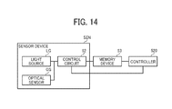
- FIG. 14 is a schematic block diagram illustrating a hardware configuration of the imaging unit according to the present embodiment.
- the imaging unit is implemented by hardware such as the sensor devices SEN and the controller 520 , illustrated in the drawing.
- FIG. 15 is an external view of the sensor device SEN according to the present embodiment.
- the sensor device SEN is configured to capture a speckle pattern, which appears on a conveyed object (i.e., a target in FIG. 15 ) such as the web 120 when the conveyed object is irradiated with light.
- the speckle pattern is an example of surface data of the web 120 .
- the sensor device SEN includes the light source LG such as a semiconductor laser light source (e.g., a laser diode or LD) and an optical system such as a collimate optical system.
- the sensor device SEN includes the optical sensor OS (a CMOS image sensor) and a telecentric optics (TO) to condense light to image the speckle pattern on the optical sensor OS.
- the CMOS image sensors (the optical sensors OS) of different sensor devices SEN capture the image of the speckle pattern, for example, at a time TM 1 and a time TM 2 , respectively.
- the controller 520 Based on the image obtained at the time TM 1 and the image obtained at the time TM 2 , the controller 520 performs cross-correlation operation. In this case, the controller 520 calculates, for example, the amount by which the conveyed object has actually moved from the time TM 1 to the TM 2 , from one sensor device SEN toward the other sensor device SEN. Details are to be described later.
- the same sensor device SEN can capture the speckle pattern at the time TM 1 and at the time TM 2 , and the cross-correlation operation can be made using the image of the speckle pattern captured at the time TM 1 and that captured at the time TM 2 .
- the controller 520 can output the amount of movement of the conveyed object from the time TM 1 to the time TM 2 .
- the sensor device SEN is 15 mm in width, 60 mm in depth, and 32 mm in height (15 ⁇ 60 ⁇ 32).
- the light source is not limited to devices employing laser light but can be, for example, a light emitting diode (LED) or an organic electro luminescence (EL).
- the pattern indicating the surface data is not limited to the speckle pattern. Descriptions are given below of an example in which the pattern indicating the surface data is a speckle pattern.
- the CMOS image sensor (the optical sensor OS) is an example hardware structure to implement an imaging unit 16 ( 16 A or 16 B) to be described later.
- the controller 520 performs the correlation operation in this example, in one embodiment, a field-programmable gate array (FPGA) circuit of one of the sensor devices SEN performs the correlation operation.
- the control circuit 52 controls the optical sensor OS, the light source LG, and the like disposed inside the sensor device SEN. Specifically, the control circuit 52 is an example hardware to implement the function of the change unit 110 F 70 .
- the control circuit 52 outputs trigger signals to the optical sensor OS to control the shutter timing of the optical sensor OS.
- the control circuit 52 causes the optical sensor OS to generate the two-dimensional images and acquires the two-dimensional images therefrom. Then, the control circuit 52 transmits the two-dimensional images generated by the optical sensor OS to a memory device 53 .
- the memory device 53 is a so-called memory. It is preferable that the two-dimensional image transmitted from the control circuit 52 can be divided and the memory device 53 can store the divided images in different memory ranges.
- the controller 520 performs operations using the image data stored in the memory device 53 .
- the control circuit 52 and the controller 520 are, for example, central processing units (CPUs) or electronic circuits. Note that the control circuit 52 , the memory device 53 , and the controller 520 are not necessarily different devices. For example, the control circuit 52 and the controller 520 can be implemented by a single CPU.
- FIG. 16 is a schematic block diagram of a functional configuration incorporating the surface detecting unit according to an embodiment. Descriptions below are based on a combination of the surface detecting units 110 F 10 (the reference character “K” and “C” are added thereto in FIG. 16 ) for the liquid discharge head units 210 K and 210 C.
- the surface detecting unit 110 F 10 K for the liquid discharge head unit 210 K outputs a detection result concerning a position A
- the surface detecting unit 110 F 10 C for the liquid discharge head unit 210 C outputs a detection result concerning a position B.
- the surface detecting unit 110 F 10 K for the liquid discharge head unit 210 K includes, for example, an imaging unit 16 A, an imaging controller 14 A, an image memory 15 A, and the change unit 110 F 70 .
- the surface detecting unit 110 F 10 C for the liquid discharge head unit 210 C is similar in configuration to the surface detecting unit 110 F 10 and includes an imaging unit 16 B, an imaging controller 14 B, an image memory 15 B, and a change unit 110 F 70 B.
- the surface detecting unit 110 F 10 K concerning the position A is described below.
- the imaging unit 16 A captures an image of the web 120 conveyed in the conveyance direction 10 .
- the imaging unit 16 A is implemented by, for example, the optical sensor OS (illustrated in FIG. 15 ).
- the imaging controller 14 A includes a shutter controller 141 A, an image acquisition unit 142 A, and the change unit 110 F 70 .
- the imaging controller 14 A is implemented by, for example, the control circuit 52 (illustrated in FIG. 14 ).
- the image acquisition unit 142 A captures the image generated by the imaging unit 16 A.
- the shutter controller 141 A controls the timing of imaging by the imaging unit 16 A.
- the change unit 110 F 70 changes the origin of detection by the surface detecting unit 110 F 10 during image formation.
- the image memory 15 A stores the image acquired by the imaging controller 14 A.
- the image memory 15 A is implemented by, for example, the memory device 53 and the like (illustrated in FIG. 14 ).
- the calculator 110 F 60 is configured to calculate, based on the images respectively recorded in the image memories 15 A and 15 B, the position of a pattern on the web 120 , the speed at which the web 120 is conveyed (hereinafter “conveyance speed”), and the amount by which the web 120 is conveyed (hereinafter “conveyance amount”).
- the calculator 110 F 60 outputs, to the shutter controllers 141 A and 141 B, data on time difference ⁇ t indicating the timing of shooting (shutter timing). In other words, the calculator 110 F 60 instructs the shutter controller 141 A of shutter timings of imaging at the position A and imaging at the position B with the time difference ⁇ t.
- the calculator 110 F 60 is implemented by, for example, the controller 520 .
- the web 120 has diffusiveness on a surface thereof or in an interior thereof. Accordingly, when the web 120 is irradiated with light (e.g., laser beam), the reflected light is diffused. The diffuse reflection creates a pattern on the web 120 . The pattern is made of spots called “speckles” (i.e., a speckle pattern). Accordingly, when the web 120 is shot, an image of the speckle pattern is obtained. From the image, the position of the speckle pattern is known, and the location of a specific portion of the web 120 can be detected. The speckle pattern is generated as the light emitted to the web 120 interferes with a rugged shape caused by a projection and a recess, on the surface or inside of the web 120 .
- light e.g., laser beam
- the speckle pattern on the web 120 is conveyed as well.
- the amount of movement of the speckle pattern is obtained.
- the calculator 110 F 60 obtains the amount of movement of the speckle pattern based on the detection of an identical speckle pattern, thereby obtaining the amount of movement of the web 120 .
- the calculator 110 F 60 converts the calculated amount of movement into an amount of movement per unit time, thereby obtain the speed at which the web 120 has moved.
- the amount of movement and speed of movement of the web 120 obtained are not limited to those in the conveyance direction 10 . Since the imaging unit 16 A outputs two-dimensional image data, the calculator 110 F 60 can calculate the amount or speed of two-dimensional movement.
- the head moving unit 110 F 80 functions to move the liquid discharge head unit 210 based on the amount or speed of movement in the orthogonal direction 20 calculated by the calculator 110 F 60 .
- the head moving unit 110 F 80 is implemented by, for example, the hardware configuration illustrated in FIG. 8 .
- a control unit 110 F 20 (serving as an image formation control unit, illustrated in FIG. 13 ) functions to control the timing of discharge of liquid from the liquid discharge head unit based on the detection result generated by the surface detecting unit 110 F 10 .
- the control unit 110 F 20 is implemented by, for example, the hardware structure illustrated in FIG. 9 .
- the control unit 110 F 20 controls the timing of discharge of the liquid discharge head unit 210 based on the displacement of amount of movement in the conveyance direction 10 or the displacement of speed of movement, calculated by the calculator 110 F 60 .
- the liquid discharge apparatus 110 can further include a measuring instrument such as an encoder 300 illustrated in FIG. 2 .
- the encoder 300 is attached to a rotation shaft of the roller 230 , which is a driving roller. Then, the amount of movement of the web 120 can be measured based on the amount of rotation of the roller 230 .
- the liquid discharge apparatus 110 can discharge ink to the web 120 accurately.
- the calculator 110 F 60 performs the correlation operation as follows.
- FIG. 17 is a diagram of a configuration for the correlation operation according to the present embodiment.
- the calculator 110 F 60 performs the correlation operation with the illustrated configuration, to calculate the relative position of the web 120 in the orthogonal direction at the position where the image data is obtained, the amount of movement, speed of movement, or a combination thereof.
- the correlation operation With the correlation operation, the amount of displacement of the web 120 from the ideal position at the timing when the image data is obtained and the speed of movement can be calculated.
- the calculator 110 F 60 includes a 2D Fourier transform FT 1 (a first 2D Fourier transform), a 2D Fourier transform FT 2 (second 2D Fourier transform), a correlation image data generator DMK, a peak position search unit SR, an arithmetic unit CAL (or arithmetic logical unit), and a transform-result memory MEM.
- FT 1 a first 2D Fourier transform
- 2D Fourier transform FT 2 second 2D Fourier transform
- DMK correlation image data generator
- SR peak position search unit
- CAL or arithmetic logical unit
- MEM transform-result memory
- the 2D Fourier transform FT 1 is configured to transform the first image data D 1 .
- the 2D Fourier transform FT 1 includes a Fourier transform unit FT 1 a for transform in the orthogonal direction 20 and a Fourier transform unit FT 1 b for transform in the conveyance direction 10 .
- the Fourier transform unit FT 1 a performs one-dimensional transform of the first image data D 1 in the orthogonal direction 20 . Based on the result of transform by the Fourier transform unit FT 1 a for orthogonal direction, the Fourier transform unit FT 1 b performs one-dimensional transform of the first image data D 1 in the conveyance direction 10 . Thus, the Fourier transform unit FT 1 a and the Fourier transform unit FT 1 b perform one-dimensional transform in the orthogonal direction 20 and the conveyance direction 10 , respectively.
- the 2D Fourier transform FT 1 outputs the result of transform to the correlation image data generator DMK.
- the 2D Fourier transform FT 2 is configured to transform the second image data D 2 .
- the 2D Fourier transform FT 2 includes a Fourier transform unit FT 2 a for transform in the orthogonal direction 20 , a Fourier transform unit FT 2 b for transform in the conveyance direction 10 , and a complex conjugate unit FT 2 c.
- the Fourier transform unit FT 2 a performs one-dimensional transform of the second image data D 2 in the orthogonal direction 20 .
- the Fourier transform unit FT 2 b Based on the result of transform by the Fourier transform unit FT 2 a for orthogonal direction, the Fourier transform unit FT 2 b performs one-dimensional transform of the second image data D 2 in the conveyance direction 10 .
- the Fourier transform unit FT 2 a and the Fourier transform unit FT 2 b perform one-dimensional transform in the orthogonal direction 20 and the conveyance direction 10 , respectively.
- the complex conjugate unit FT 2 c calculates a complex conjugate of the results of transform by the Fourier transform unit FT 2 a (for orthogonal direction) and the Fourier transform unit FT 2 b (for conveyance direction). Then, the 2D Fourier transform FT 2 outputs, to the correlation image data generator DMK, the complex conjugate calculated by the complex conjugate unit FT 2 c.
- the correlation image data generator DMK then generates the correlation image data, based on the transform result of the first image data D 1 , output from the 2D Fourier transform FT 1 , and the transform result of the second image data D 2 , output from the 2D Fourier transform FT 2 .
- the correlation image data generator DMK includes an adder DMKa and a 2D inverse Fourier transform unit DMKb.
- the adder DMKa adds the transform result of the first image data D 1 to that of the second image data D 2 and outputs the result of addition to the 2D inverse Fourier transform unit DMKb.
- the 2D inverse Fourier transform unit DMKb performs 2D inverse Fourier transform of the result generated by the adder DMKa.
- the correlation image data is generated through 2D inverse Fourier transform.
- the 2D inverse Fourier transform unit DMKb outputs the correlation image data to the peak position search unit SR.
- the peak position search unit SR searches the correlation image data for a peak position (a peak luminance or peak value), at which rising is sharpest.
- a peak position a peak luminance or peak value
- values indicating the intensity of light, that is, the degree of luminance are input.
- the luminance values are input in matrix.
- the luminance values are arranged at a pixel pitch of the optical sensor OS (i.e., an area sensor), that is, pixel size intervals. Accordingly, the peak position is preferably searched for after performing so-called sub-pixel processing. Sub-pixel processing enhances the accuracy in searching for the peak position. Then, the calculator 110 F 60 can output the position, the amount of movement, and the speed of movement.
- the optical sensor OS i.e., an area sensor
- FIG. 18 is a graph illustrating the peak position searched in the correlation operation according to the present embodiment.
- the lateral axis represents the position in the conveyance direction 10 of an image represented by the correlation image data
- the vertical axis represents the luminance values of the image represented by the correlation image data.
- the luminance values indicated by the correlation image data are described below using a first data value q 1 , a second data value q 2 , and a third data value q 3 .
- the peak position search unit SR (illustrated in FIG. 17 ) searches for peak position P on a curved line k connecting the first, second, and third data values q 1 , q 2 , and q 3 .
- the peak position search unit SR calculates each difference between the luminance values indicated by the correlation image data. Then, the peak position search unit SR extracts a largest difference combination, meaning a combination of luminance values between which the difference is largest among the calculated differences. Then, the peak position search unit SR extracts combinations of luminance values adjacent to the largest difference combination.
- the peak position search unit SR can extract three data values, such as the first, second, and third data values q 1 , q 2 , and q 3 in the graph. The peak position search unit SR calculates the curved line K connecting these three data values, thereby obtaining the peak position P.
- the peak position search unit SR can reduce the amount of operation such as sub-pixel processing to increase the speed of searching for the peak position P.
- the position of the combination of luminance values between which the difference is largest means the position at which rising is sharpest.
- the manner of sub-pixel processing is not limited to the description above.
- FIG. 19 is a diagram of example results of correlation operation and illustrates a profile of strength of correlation of a correlation function.
- X axis and Y axis represent serial number of pixel.
- the peak position search unit SR (illustrated in FIG. 17 ) searches for a peak position such as “correlation peak” in the graph.
- the arithmetic unit CAL calculates the relative position, amount of movement, or speed of movement of the web 120 , or a combination thereof. For example, the arithmetic unit CAL calculates the difference between a center position of the correlation image data and the peak position calculated by the peak position search unit SR, to obtain the relative position and the amount of movement.
- the arithmetic unit CAL divides the amount of movement by time, to obtain the speed of movement.
- the calculator 110 F 60 can calculate, through the correlation operation, the relative position at the position of the sensor, amount of movement, or speed of movement of the web 120 .
- the methods of calculation of the relative position, the amount of movement, or the speed of movement are not limited to those described above.
- the calculator 110 F 60 obtains the relative position, amount of movement, or speed of movement through the following method.
- the calculator 110 F 60 binarizes each luminance value of the first image data D 1 and the second image data D 2 . That is, the calculator 110 F 60 binarizes a luminance value not greater than a predetermined threshold into “0” and a luminance value greater than the threshold into “1”. Then, the calculator 110 F 60 may compare the binarized first and second image data D 1 and D 2 to obtain the relative position.
- the peak position occurs at a position displaced in the X direction when there are fluctuations in the X direction.
- the calculator 110 F 60 can adapt a different method to obtain the relative position, amount of movement, or speed of movement.
- the calculator 110 F 60 can adapt so-called pattern matching processing to detect the relative position based on a pattern taken in the image data.
- the liquid discharge apparatus 110 can obtain a detection result indicating the position of the web 120 in at least one of the conveyance direction 10 and the orthogonal direction 20 , with a high accuracy.
- the sensor device SEN can be shared for detecting respective positions in the conveyance direction 10 and the orthogonal direction 20 , which reduces the cost of detecting positions in both directions. Additionally, the space for the detection can be small since the number of sensors is reduced.
- FIG. 20 is a flowchart of surface detection and position adjustment of a liquid discharge head unit during image formation.
- the process illustrated in FIG. 20 is executed after the process illustrated in FIG. 12 , that is, after 1) the position detecting unit 110 F 40 illustrated in FIG. 13 detects the operation position (liquid discharge position), 2) the head moving unit 110 F 80 , instructed by the adjusting unit 110 F 50 , adjusts the respective landing positions of the liquid discharge head units 210 in the orthogonal direction 20 to the adjusted positions, and 3) the change unit 110 F 70 changes the position of origin of detection of each of the surface detecting units 110 F 10 .
- the liquid discharge head unit 210 is moved in the orthogonal direction 20 during image formation, with the adjusted position set by the head moving unit 110 F 80 instructed by the adjusting unit 110 F 50 used as the initial position. Then, the liquid discharge apparatus 110 forms an image on the web 120 according to the image data, while performing the processing illustrated in FIG. 20 .
- the processing illustrated in FIG. 20 relates to one liquid discharge head unit, for example, the liquid discharge head unit 210 C in the example illustrated in FIG. 2 .
- the processing illustrated in FIG. 20 is performed in parallel or at a different timing.
- performing the processing illustrated in FIG. 20 for different colors in parallel is preferred, but the processing is not necessarily completely simultaneous. What is desirable is moving respectively the liquid discharge head units 210 in the orthogonal direction 20 to follow the meandering web 120 during image formation.
- the liquid discharge apparatus 110 calculates the position and the like of the conveyed object based on a plurality of sensor data. Specifically, at S 11 , the surface sensor devices detect the positions of the web 120 . The liquid discharge apparatus 110 acquires the plurality of sensor data representing the respective detection results output by the surface sensor devices. Subsequently, the calculator 110 F 60 calculates the amount of displacement of the recording medium based on the plurality of sensor data, that is, a plurality of detection results.
- the liquid discharge apparatus 110 moves the liquid discharge head unit 210 in the orthogonal direction 20 based on the detection result acquired at S 11 , to compensate for the displacement of the web 120 in the orthogonal direction 20 , indicated by the detection result acquired at S 11 . That is, at S 12 , the liquid discharge head unit 210 is moved by the amount of displacement of the web 120 detected at S 11 , to cancel the displacement of the web 120 .
- the liquid discharge head unit 210 can follow the meandering of the web 120 during image formation.
- the liquid discharge apparatus 110 can adjust the timing of discharge of the liquid.
- FIG. 21 is a timing chart of calculation of the amount of displacement of the conveyed object, performed by the liquid discharge apparatus 110 according to the present embodiment.
- the liquid discharge apparatus 110 calculates the amount of movement or the like based on data generated by a plurality of sensor data. Specifically, the liquid discharge apparatus 110 outputs the result of calculation indicating the displacement based on first and second detection results SD 1 and SD 2 .
- the first and second detection results SD 1 and SD 2 are represented by sensor data output from any two of the surface sensor devices illustrated in FIG. 2 . Then, the liquid discharge apparatus 110 calculates the amount of displacement based on the plurality of detection results represented by the respective sensor data.
- the amount of displacement is calculated for each liquid discharge head unit 210 .
- the displacement of the web 120 is calculated based on the detection result generated by the sensor device SENC (illustrated in FIG. 2 ) and that by the sensor device SENK disposed upstream from and next to the sensor device SENC.
- the first detection result SD 1 is generated by the sensor device SENK
- the second detection result SD 2 is generated by the sensor device SENC.
- L 2 (see FIG. 16 ) represents the distance between the sensor device SENK and the sensor device SENC (interval between the surface sensor devices), V represents the conveyance speed calculated based on the data generated by the optical sensors OS, and T 2 represents a travel time for the web 120 (conveyed object) to be conveyed from position detected by the sensor device SENK to the position detected by the sensor device SENC.
- n T 2 /A
- the calculation result is referred to as a displacement ⁇ X.
- a displacement ⁇ X For example, in a case of a detection cycle “ 0 ” in FIG. 21 , the first detection result SD 1 before the travel time T 2 is compared with the second detection result SD 2 at the detection cycle “ 0 ”, to calculate the displacement ⁇ X of the web 120 .
- the liquid discharge apparatus 110 calculates the amount by which the position of the recording medium is expected to change till the recording medium reaches the location of surface sensor device. Then, the liquid discharge apparatus 110 drives the actuator ACT illustrated in FIG. 8 .
- the liquid discharge apparatus 110 controls the actuator ACT (illustrated in FIG. 8 ) to move the liquid discharge head unit 210 C (illustrated in FIG. 8 ) in the orthogonal direction 20 , to compensate for the displacement ⁇ .
- the liquid discharge apparatus 110 can form an image on the conveyed object with a high accuracy.
- the displacement is calculated based on the two detection results, that is, the detection results generated by the two different surface sensor devices, the displacement of the conveyed object can be calculated without multiplying the position data of the sensors. This operation can suppress the accumulation of detection errors by the surface sensor devices.
- the amount of displacement can be calculated similarly for other liquid discharge head units 210 .
- the first detection result SD 1 generated by the sensor device SENC and the second detection result SD 2 generated by the sensor device SENM are used to calculate the displacement of the web 120 for adjusting the magenta liquid discharge head unit 210 M (illustrated in FIG. 2 ).
- the first detection result SD 1 generated by the sensor device SENM and the second detection result SD 2 generated by the sensor device SENY are used to calculate the displacement of the web 120 for adjusting the yellow liquid discharge head unit 210 Y (illustrated in FIG. 2 ).
- the liquid discharge apparatus 110 further includes another sensor device SEN upstream from the sensor device SENK in the conveyance direction 10 , the displacement of the web 120 for adjusting the liquid discharge head unit 210 K can be calculated.
- the surface sensor device (sensor device SEN) to generate the detection result SD 1 is not limited to the sensor device SEN disposed next to and upstream from the liquid discharge head unit 210 to be moved. That is, the first detection result SD 1 can be generated by any of the sensor devices SEN disposed upstream from the liquid discharge head unit 210 to be moved. The detection result generated by any one of the sensor devices SENK and SENC can be used as the first detection result SD 1 to calculate the displacement of the web 120 for adjusting the yellow liquid discharge head unit 210 Y.
- the second detection result SD 2 is preferably generated by the sensor device SEN closest to the liquid discharge head unit 210 to be moved.
- the displacement of the conveyed object can be calculated based on three or more detection results.
- the liquid discharge head units 210 are respectively moved, and the liquid is discharged onto the web 120 (i.e., the recording medium) to form an image thereon.
- the surface sensor device is preferably disposed close to the ink landing position.
- the distance between the ink landing position and the surface sensor device is preferably short.
- detection error can be suppressed. Accordingly, the liquid discharge apparatus 110 can accurately detect, with the surface sensor device, at least one of the position, speed of movement, and amount of movement of the recording medium in the conveyance direction 10 and the orthogonal direction 20 .
- the position close to the landing position is an area between the first roller CR 1 and the second roller CR 2 .
- the sensor device SENK for black is preferably disposed in an inter-roller range INTK 1 between the first and second rollers CR 1 K and CR 2 K.
- the sensor device SENC for cyan is preferably disposed in an inter-roller range INTC 1 between the first and second rollers CR 1 C and CR 2 C.
- the sensor device SENM for magenta is preferably disposed in an inter-roller range INTM 1 between the first and second rollers CR 1 M and CR 2 M.
- the sensor device SENY for yellow is preferably disposed in an inter-roller range INTY 1 between the first and second rollers CR 1 Y and CR 2 Y.
- the inter-roller ranges INTY 1 , INTC 1 , INTM 1 , and INTY 1 are collectively referred to as “inter-roller ranges INT 1 ”.
- the surface sensor device disposed between the first and second rollers CR 1 and CR 2 can detect the recording medium at a position close to the ink landing position.
- the conveyance speed in the conveyance direction 10 and the speed of meandering (the speed of movement in the orthogonal direction 20 ) of the conveyed object is relatively stable between the rollers. Accordingly, the liquid discharge apparatus 110 can accurately detect the position, speed of movement, or amount of movement of the recording medium.
- the surface sensor device is disposed between the ink landing position and the first roller CR 1 .
- the surface sensor device is preferably disposed upstream from the ink landing position in the conveyance direction 10 .
- the sensor device SENK for black is, more preferably, disposed in a range extending from the black ink landing position PK upstream to the first roller CR 1 K for black in the conveyance direction 10 (hereinafter “upstream range INTK 2 ”).
- the sensor device SENC for cyan is, more preferably, disposed in a range extending from the cyan ink landing position PC upstream to the first roller CR 1 C for cyan (hereinafter “upstream range INTC 2 ”).
- the sensor device SENM for magenta is, more preferably, disposed in a range extending from the magenta ink landing position PM upstream to the first roller CR 1 M for magenta (hereinafter “upstream range INTM 2 ”).
- the sensor device SENY for yellow is, more preferably, disposed in a range extending from the yellow ink landing position PY upstream to the first roller CR 1 Y for yellow (hereinafter “upstream range INTY 2 ”).
- the liquid discharge apparatus 110 can detect the position, speed of movement, or amount of movement of the conveyed object with a high accuracy.
- the surface sensor devices thus disposed are upstream from the landing position at which ink droplets land on the recording medium in the conveyance direction 10 .
- the liquid discharge apparatus 110 can initially detect the position of the conveyed object with the surface sensor device based on the data output by the surface sensor device on the upstream side, and then calculate the position or speed of movement of the liquid discharge head unit 210 and timing of ink discharge (i.e., operation timing) of the liquid discharge head unit 210 .
- the liquid discharge head unit 210 can discharge ink at the calculated position and the calculated timing.
- the surface sensor device is disposed directly below the liquid discharge head unit 210 , in some cases, a delay of control action causes misalignment in color superimposition (out of color registration) resulting in color shift. Accordingly, when the location of surface sensor device is upstream from the ink landing position, misalignment in color superimposition is suppressed, improving image quality. There are cases where layout constraints hinder disposing the surface sensor device adjacent to the landing position. Accordingly, the surface sensor device is preferably disposed closer to the first roller CR 1 from the ink landing position.
- the location of surface sensor device can be directly below the liquid discharge head unit 210 .
- the surface sensor device disposed directly below the head unit can accurately detect the amount of movement of the recording medium directly below the head unit. Therefore, in a configuration in which the speed of calculation of movement amount or the like is relatively fast, the surface sensor device is preferably disposed closer to the position directly below the liquid discharge head unit 210 .
- the location of surface sensor device is not limited to the position directly below the liquid discharge head unit 210 , and similar calculation is feasible when the surface sensor device is disposed otherwise.
- the displacement sensor PSEN is disposed on the same side of the web 120 as the liquid discharge head units 210 , so as to detect the image patterns PTN illustrated in FIG. 5 .
- the sensor devices SEN are disposed on the side of the web 120 opposite the liquid discharge head units 210 and the displacement sensor PSEN.
- the displacement sensor PSEN is disposed on the front side of the web 120 while the sensor devices SEN are disposed on the back side of the web 120 .
- detection of a speckle pattern is easier on a side on which liquid discharge is not performed.
- the sensor device SEN can be disposed on the front side of the web 120 when the sensor device SEN can detect a position to which liquid is not discharged.
- the liquid discharge apparatus 110 changes the operation position in the orthogonal direction 20 and the position of origin of the surface detecting unit 110 F 10 based on the detection by the position detecting unit 110 F 40 (the displacement sensor PSEN) during a period in which image formation is not performed. Then, the liquid discharge apparatus 110 can calculate the ink discharge timing (i.e., operation timing), the amount by which the liquid discharge head unit 210 is to be moved, or a combination thereof, based on the detection result generated by the surface detecting unit 110 F 10 , during image formation.
- the ink discharge timing i.e., operation timing
- the liquid discharge head unit 210 can accurately change the landing position in at least one of the conveyance direction 10 and the orthogonal direction 20 .
- the liquid discharge apparatus 110 includes the position detecting unit 110 F 40 to calculate the amount of displacement of the web, for example, as illustrated in FIG. 6 .
- the adjusting unit 110 F 50 moves the liquid discharge head unit 210 in the orthogonal direction 20 , for example, as illustrated in FIG. 7 .
- the conveyed object When the conveyed object is conveyed askew as illustrated in FIG. 4 , the conveyed object is displaced in the orthogonal direction 20 , resulting in misalignment in color superimposition and degrading image quality. Accordingly, the liquid discharge head unit 210 is moved in the orthogonal direction 20 to eliminate the displacement. As the amount of displacement decreases, the accuracy of the landing position of liquid can improve. Further, in accordance with the position adjustment of the liquid discharge head unit 210 , the origin of detection by the surface detecting unit 110 F 10 is changed.
- the liquid discharge apparatus 110 can minimize the misalignment in color superimposition to improve image quality.
- One sensor device can double as the surface sensor and the displacement sensor (i.e., used as a dual-purpose sensor). Descriptions are given below of a variation in which the dual-purpose sensor is disposed outside an image formation area.
- the dual-purpose sensor is disposed at an end of the web 120 in the orthogonal direction 20 .
- the dual-purpose sensor is disposed on a side of the web 120 on which the liquid discharge head units 210 are disposed.
- the image patterns PTN (PTN 1 , PTN 2 , and PTN 3 ) illustrated in FIG. 5 are formed, for example, in an end portion of the web 120 .
- the liquid discharge apparatus 110 can further include a light source for detecting the image pattern PTN different from the light source used to detect the pattern of the web 120 (e.g., speckle pattern).
- the liquid discharge apparatus 110 can further have a capability to adjust the amount of light emitted from the light source for detecting the image pattern PTN.
- a sensor located downstream from at least two liquid discharge head units 210 serves as the displacement sensor.
- the sensor provided for (disposed close to) the liquid discharge head unit 210 to be moved in image formation serves as the surface sensor.
- Using one sensor as both of the surface sensor and the displacement sensor can reduce the number of sensors and reduce the cost of the apparatus.
- One or more of aspects of this disclosure can adapt to a liquid discharge system including at least one liquid discharge apparatus.
- the liquid discharge head unit 210 K and the liquid discharge head unit 210 C are housed in a case of one apparatus, and the liquid discharge head unit 210 M and the liquid discharge head unit 210 Y are housed in a case of another apparatus.
- the liquid discharge system includes the two apparatuses.
- aspects of this disclosure can adapt to a liquid discharge system to discharge liquid other than ink.
- the liquid is a recording liquid of another type or a fixing solution.
- aspects of this disclosure can adapt to a liquid discharge apparatus to discharge liquid other than ink and a system including such a liquid discharge apparatus.
- the image (an article) produced can be, for example, a three-dimensional object (a 3D-fabricated object).
- a single support can double as the first and second supports as described below.
- FIG. 22 is a schematic view of a liquid discharge apparatus according to a variation. This configuration differs from the configuration illustrated in FIG. 2 regarding the locations of the first support and the second support.
- the liquid discharge apparatus 110 illustrated in FIG. 22 includes supports RL 1 , RL 2 , RL 3 , RL 4 , and RL 5 , serving as the first and second supports.
- one support can double as the second support (e.g., the conveyance roller CR 2 K in FIG. 2 ) disposed upstream from the downstream one of adjacent two liquid discharge head units and the first support (e.g., the conveyance roller CR 1 C in FIG. 2 ) disposed upstream from the upstream one of the adjacent two liquid discharge head units.
- the support according to the modification which doubles as the first and second supports, can be either a roller or a curved plate.
- the conveyed object is not limited to recording media such as paper sheets but can be any material to which liquid adheres, even temporarily.
- Examples of the material to which liquid adheres include paper, thread, fiber, cloth, leather, metal, plastic, glass, wood, ceramics, and a combination thereof.
- the liquid discharge apparatus 110 can convey a belt as the conveyed object.
- FIG. 23 is a schematic view of a liquid discharge apparatus according to another variation.
- head units 350 C, 350 M, 350 Y, and 350 K discharge ink droplets to form an image on the outer side of the loop of a transfer belt 328 .
- the head units 350 C, 350 M, 350 Y, and 350 K are also collectively referred to as head units 350 .
- a drier 370 dries an image formed on the transfer belt 328 into a film.
- the liquid discharge apparatus 110 transfers the image in the form of film, conveyed on the transfer belt 328 , onto a sheet.
- a cleaning roller 323 cleans the surface of the transfer belt 328 after the transfer.
- the head units 350 C, 350 M, 350 Y, and 350 K, the drier 370 , the cleaning roller 323 , and the transfer roller 330 are disposed around the transfer belt 328 .
- the transfer belt 328 is stretched taut around a driving roller 321 , an opposing roller 322 (a transfer-backup roller), four shape-keeping rollers 324 , and eight support rollers 325 C 1 , 325 C 2 , 325 M 1 , 325 M 2 , 325 Y 1 , 325 Y 2 , 325 K 1 , and 325 K 2 .
- the driving roller 321 rotates driven by a belt driving motor 327
- the transfer belt 328 rotates in the conveyance direction 10 indicated an arrow illustrated in FIG. 23 .
- a transfer motor 331 drives the transfer roller 330 .
- a sensor device 332 C is disposed between the support rollers 325 C 1 and 325 C 2 and upstream from the ink discharge position of the head unit 350 C in the conveyance direction 10 in which the transfer belt 328 rotates.
- the sensor device 332 M is disposed for the head unit 350 M.
- a displacement sensor PSEN 3 is disposed downstream from the drier 370 in the conveyance direction 10 .
- the displacement sensor PSEN 3 can be disposed upstream from the drier 370 .
- actuators 333 M, 333 Y, and 333 K are provided, respectively.
- the actuator 333 M moves the head unit 350 M in the direction orthogonal to the conveyance direction 10 in which the transfer belt 328 rotates.
- the actuators 333 Y and 333 K move the head units 350 Y and 350 K, respectively, in the direction orthogonal to the conveyance direction 10 .
- a control board 340 moves (with the actuators 333 M, 333 Y, and 333 K) the head units 350 M, 350 Y, and 350 K based on the data obtained from the displacement sensor PSEN 3 , before image formation. Additionally, the control board 340 detects the amount of movement of the transfer belt 328 in the conveyance direction 10 and that in the direction orthogonal thereto, based on the image data obtained from the sensor devices 332 C, 332 M, 332 Y, and 332 K. Additionally, according to the amount of movement of the transfer belt 328 in the orthogonal direction, the control board 340 controls the actuators 333 M, 333 Y, and 333 K to move the head units 350 M, 350 Y, and 350 K in the orthogonal direction. Additionally, according to the amount of movement of the transfer belt 328 in the conveyance direction 10 , the control board 340 controls the timing of liquid discharge from the head units 350 M, 350 Y, and 350 K.
- the control board 340 outputs driving signals to the belt driving motor 327 and the transfer motor 331 .
- the liquid discharge apparatus 110 can move the head units 350 M, 350 Y, and 350 K in the orthogonal direction, corresponding to the amount of movement detected. Accordingly, the liquid discharge apparatus 110 can form a high-quality image on the transfer belt 328 .
- the liquid discharge apparatus 110 can change the timing of liquid discharge from the head units 350 M, 350 Y, and 350 K in response to the amount of rotation detected. Accordingly, the liquid discharge apparatus 110 can form a high-quality image on the transfer belt 328 .
- the amount of movement of the transfer belt 328 in the conveyance direction 10 and that in the direction orthogonal thereto are calculated based on the image data obtained from the sensor devices 332 C, 332 M, 332 Y, and 332 K. Alternatively, the amount of movement in only one of those directions can be calculated.
- the head unit 350 C does not include an actuator in the above-described example, alternatively, an actuator can be provided. Then, the head unit 350 C is moved in the direction orthogonal to the conveyance direction 10 , thereby adjusting the position of the head unit 350 C in the orthogonal direction at the time of image transfer from the transfer belt 328 onto the sheet P.
- the operation described above can adopt to forming an image using one head unit.
- aspects of this disclosure can adapt to any apparatus to perform an operation or processing on a conveyed object, using a line head unit including heads lined in a direction orthogonal to the direction of conveyance of the conveyed object.
- aspects of this disclosure can adapt to an apparatus that conveys a substrate (conveyed object) and includes a laser head unit to perform laser patterning, as image formation, on the substrate.
- a plurality of such laser head units can be lined in the direction orthogonal to the direction of conveyance of the substrate.
- the apparatus detects the result of laser writing to adjust the position of the head unit and then detects the position of the substrate to move the head unit based on the result of detection of the substrate.
- the position on the substrate irradiated with laser light is the operation position of the head.
- patterning is an example of image formation.
- the number of the head units is not necessarily two or more. Aspects of this disclosure can adapt to a device configured to keep performing processing at a reference position, on a conveyed object.
- one or more of aspects of this disclosure can be embodied as a method performed by a computer of a conveyance device, an information processing system including at least one information processing apparatus, or the combination thereof to cause the apparatus to discharge liquid, and at least a portion of the method can be implemented by a program.
- Processing circuitry includes a programmed processor, as a processor includes circuitry.
- a processing circuit also includes devices such as an application specific integrated circuit (ASIC), digital signal processor (DSP), field programmable gate array (FPGA), and conventional circuit components arranged to perform the recited functions.
- ASIC application specific integrated circuit
- DSP digital signal processor
- FPGA field programmable gate array
Abstract
Description
Claims (14)
Applications Claiming Priority (4)
| Application Number | Priority Date | Filing Date | Title |
|---|---|---|---|
| JP2017050506 | 2017-03-15 | ||
| JP2017-050506 | 2017-03-15 | ||
| JP2018044808A JP7010074B2 (en) | 2017-03-15 | 2018-03-12 | Image forming apparatus, image forming system and processing position moving method |
| JP2018-044808 | 2018-03-12 |
Publications (2)
| Publication Number | Publication Date |
|---|---|
| US20180270366A1 US20180270366A1 (en) | 2018-09-20 |
| US10334130B2 true US10334130B2 (en) | 2019-06-25 |
Family
ID=63519748
Family Applications (1)
| Application Number | Title | Priority Date | Filing Date |
|---|---|---|---|
| US15/921,616 Expired - Fee Related US10334130B2 (en) | 2017-03-15 | 2018-03-14 | Image forming apparatus, image forming system, and position adjustment method |
Country Status (1)
| Country | Link |
|---|---|
| US (1) | US10334130B2 (en) |
Families Citing this family (4)
| Publication number | Priority date | Publication date | Assignee | Title |
|---|---|---|---|---|
| JP7073928B2 (en) | 2017-06-14 | 2022-05-24 | 株式会社リコー | Conveyor device, liquid discharge device, reading device, image forming device, control method of the transfer device |
| JP7087497B2 (en) | 2018-03-16 | 2022-06-21 | 株式会社リコー | Recording medium support device and image forming device |
| JP7312812B2 (en) * | 2019-02-19 | 2023-07-21 | 株式会社Fuji | Parts mounting machine |
| JP2022085731A (en) | 2020-11-27 | 2022-06-08 | 株式会社リコー | Conveyance device and image formation apparatus |
Citations (34)
| Publication number | Priority date | Publication date | Assignee | Title |
|---|---|---|---|---|
| JP2002137509A (en) | 2000-11-06 | 2002-05-14 | Canon Inc | Printer and print system |
| US20020081132A1 (en) | 2000-12-22 | 2002-06-27 | Atsushi Miyamoto | Printing system |
| US20020131804A1 (en) | 2001-03-16 | 2002-09-19 | Souichi Nakazawa | Method of setting a print start position in a continuous form printing system |
| US20030039496A1 (en) | 2001-08-24 | 2003-02-27 | Hitachi Koki Co., Ltd. | Print system and registration control method at print start time of the print system |
| US20050174379A1 (en) | 2004-01-23 | 2005-08-11 | Ricoh Printing Systems, Ltd. | Duplex printing system |
| US20100310284A1 (en) | 2008-08-01 | 2010-12-09 | Hiroyoshi Funato | Velocity detecting device and multi-color image forming apparatus |
| US20120321356A1 (en) * | 2011-06-17 | 2012-12-20 | Junshin Sakamoto | Image forming apparatus |
| US20140044460A1 (en) | 2012-08-07 | 2014-02-13 | Ricoh Company, Limited | Moving-member detecting device and image forming apparatus |
| US20140219670A1 (en) | 2013-02-05 | 2014-08-07 | Koji Masuda | Image forming apparatus, sensing method, and recording medium |
| US20140268180A1 (en) | 2013-03-15 | 2014-09-18 | Atsushi Takaura | Positional change measurement device, positional change measurement method, and image forming apparatus |
| US20150009262A1 (en) | 2013-07-02 | 2015-01-08 | Ricoh Company, Ltd. | Alignment of printheads in printing systems |
| JP2015107572A (en) | 2013-12-04 | 2015-06-11 | 株式会社Screenホールディングス | Image recorder and image recording method |
| US20150290931A1 (en) | 2013-07-02 | 2015-10-15 | Ricoh Company, Ltd. | Alignment of printheads in printing systems |
| US20160075157A1 (en) | 2014-09-17 | 2016-03-17 | Ricoh Company, Ltd. | Image forming apparatus, sensor mounting jig for image forming apparatus, and method for mounting sensor for image forming apparatus |
| US20160075155A1 (en) | 2014-09-11 | 2016-03-17 | SCREEN Holdings Co., Ltd. | Printing apparatus and printing method |
| JP2016050055A (en) | 2014-08-29 | 2016-04-11 | 株式会社Screenホールディングス | Image recording device and image recording method |
| US20160114576A1 (en) | 2014-10-27 | 2016-04-28 | Ricoh Company, Ltd. | Recording position control device and abnormality detecting method for same |
| US20160121602A1 (en) | 2014-10-29 | 2016-05-05 | Ricoh Company, Ltd. | Recording device discharge position adjustor and image forming apparatus incorporating same |
| JP2016083936A (en) | 2014-10-23 | 2016-05-19 | 株式会社リコー | Alignment of print head in print system |
| US20160136947A1 (en) | 2014-11-19 | 2016-05-19 | Ricoh Company, Ltd. | Inkjet recording apparatus |
| JP2016088654A (en) | 2014-10-31 | 2016-05-23 | 株式会社Screenホールディングス | Image recording device and image recording method |
| US20160250846A1 (en) * | 2015-02-26 | 2016-09-01 | Ricoh Company, Ltd. | Printhead position control |
| US20160288555A1 (en) * | 2015-03-31 | 2016-10-06 | Riso Kagaku Corporation | Inkjet printing machine |
| US20160347052A1 (en) | 2015-05-27 | 2016-12-01 | Masaya Kawarada | Distance measuring device, image forming apparatus, and distance measuring method |
| US20170106647A1 (en) | 2015-10-20 | 2017-04-20 | Ricoh Company, Ltd. | Position correction apparatus, liquid ejection apparatus, and method for correcting position |
| US20170165961A1 (en) | 2015-12-14 | 2017-06-15 | Ricoh Company, Ltd. | Liquid ejection apparatus, liquid ejection system, and liquid ejection method |
| US20170165960A1 (en) | 2015-12-14 | 2017-06-15 | Ricoh Company, Ltd. | Liquid ejection apparatus, liquid ejection system, and liquid ejection method |
| US20170187918A1 (en) * | 2015-12-25 | 2017-06-29 | SCREEN Holdings Co., Ltd. | Image processing apparatus and image processing method for a printing apparatus |
| US20170182764A1 (en) | 2015-12-25 | 2017-06-29 | Ricoh Company, Ltd. | Liquid ejection apparatus, liquid ejection system, and liquid ejection method |
| US20170266954A1 (en) | 2016-03-15 | 2017-09-21 | Ricoh Company, Ltd. | Conveyed object detection apparatus, conveyance apparatus, and conveyed object detection method |
| US20170266965A1 (en) | 2016-03-17 | 2017-09-21 | Ricoh Company, Ltd. | Liquid ejection apparatus, liquid ejection system, and liquid ejection method |
| US20170348969A1 (en) | 2016-06-07 | 2017-12-07 | Ricoh Company, Ltd. | Device including movable head and head control method |
| US20170355205A1 (en) | 2016-06-09 | 2017-12-14 | Ricoh Company, Ltd. | Conveyed object detector, conveyance device, device including movable head, conveyed object detecting method, and non-transitory recording medium storing program of same |
| US20180022088A1 (en) | 2016-07-25 | 2018-01-25 | Ricoh Company, Ltd. | Liquid discharge apparatus, liquid discharge system, and liquid discharge method |
-
2018
- 2018-03-14 US US15/921,616 patent/US10334130B2/en not_active Expired - Fee Related
Patent Citations (36)
| Publication number | Priority date | Publication date | Assignee | Title |
|---|---|---|---|---|
| JP2002137509A (en) | 2000-11-06 | 2002-05-14 | Canon Inc | Printer and print system |
| US20020081132A1 (en) | 2000-12-22 | 2002-06-27 | Atsushi Miyamoto | Printing system |
| US20020131804A1 (en) | 2001-03-16 | 2002-09-19 | Souichi Nakazawa | Method of setting a print start position in a continuous form printing system |
| US20030039496A1 (en) | 2001-08-24 | 2003-02-27 | Hitachi Koki Co., Ltd. | Print system and registration control method at print start time of the print system |
| US20050174379A1 (en) | 2004-01-23 | 2005-08-11 | Ricoh Printing Systems, Ltd. | Duplex printing system |
| US20100310284A1 (en) | 2008-08-01 | 2010-12-09 | Hiroyoshi Funato | Velocity detecting device and multi-color image forming apparatus |
| US20120321356A1 (en) * | 2011-06-17 | 2012-12-20 | Junshin Sakamoto | Image forming apparatus |
| US20140044460A1 (en) | 2012-08-07 | 2014-02-13 | Ricoh Company, Limited | Moving-member detecting device and image forming apparatus |
| US20140219670A1 (en) | 2013-02-05 | 2014-08-07 | Koji Masuda | Image forming apparatus, sensing method, and recording medium |
| US20140268180A1 (en) | 2013-03-15 | 2014-09-18 | Atsushi Takaura | Positional change measurement device, positional change measurement method, and image forming apparatus |
| US20150009262A1 (en) | 2013-07-02 | 2015-01-08 | Ricoh Company, Ltd. | Alignment of printheads in printing systems |
| US20150290931A1 (en) | 2013-07-02 | 2015-10-15 | Ricoh Company, Ltd. | Alignment of printheads in printing systems |
| JP2015107572A (en) | 2013-12-04 | 2015-06-11 | 株式会社Screenホールディングス | Image recorder and image recording method |
| JP2016050055A (en) | 2014-08-29 | 2016-04-11 | 株式会社Screenホールディングス | Image recording device and image recording method |
| US20160075155A1 (en) | 2014-09-11 | 2016-03-17 | SCREEN Holdings Co., Ltd. | Printing apparatus and printing method |
| JP2016055570A (en) | 2014-09-11 | 2016-04-21 | 株式会社Screenホールディングス | Printing device and printing method |
| US20160075157A1 (en) | 2014-09-17 | 2016-03-17 | Ricoh Company, Ltd. | Image forming apparatus, sensor mounting jig for image forming apparatus, and method for mounting sensor for image forming apparatus |
| JP2016083936A (en) | 2014-10-23 | 2016-05-19 | 株式会社リコー | Alignment of print head in print system |
| US20160114576A1 (en) | 2014-10-27 | 2016-04-28 | Ricoh Company, Ltd. | Recording position control device and abnormality detecting method for same |
| US20160121602A1 (en) | 2014-10-29 | 2016-05-05 | Ricoh Company, Ltd. | Recording device discharge position adjustor and image forming apparatus incorporating same |
| JP2016088654A (en) | 2014-10-31 | 2016-05-23 | 株式会社Screenホールディングス | Image recording device and image recording method |
| US20160136947A1 (en) | 2014-11-19 | 2016-05-19 | Ricoh Company, Ltd. | Inkjet recording apparatus |
| US20160347050A1 (en) | 2014-11-19 | 2016-12-01 | Ricoh Company, Ltd. | Inkjet recording apparatus |
| US20160250846A1 (en) * | 2015-02-26 | 2016-09-01 | Ricoh Company, Ltd. | Printhead position control |
| US20160288555A1 (en) * | 2015-03-31 | 2016-10-06 | Riso Kagaku Corporation | Inkjet printing machine |
| US20160347052A1 (en) | 2015-05-27 | 2016-12-01 | Masaya Kawarada | Distance measuring device, image forming apparatus, and distance measuring method |
| US20170106647A1 (en) | 2015-10-20 | 2017-04-20 | Ricoh Company, Ltd. | Position correction apparatus, liquid ejection apparatus, and method for correcting position |
| US20170165960A1 (en) | 2015-12-14 | 2017-06-15 | Ricoh Company, Ltd. | Liquid ejection apparatus, liquid ejection system, and liquid ejection method |
| US20170165961A1 (en) | 2015-12-14 | 2017-06-15 | Ricoh Company, Ltd. | Liquid ejection apparatus, liquid ejection system, and liquid ejection method |
| US20170187918A1 (en) * | 2015-12-25 | 2017-06-29 | SCREEN Holdings Co., Ltd. | Image processing apparatus and image processing method for a printing apparatus |
| US20170182764A1 (en) | 2015-12-25 | 2017-06-29 | Ricoh Company, Ltd. | Liquid ejection apparatus, liquid ejection system, and liquid ejection method |
| US20170266954A1 (en) | 2016-03-15 | 2017-09-21 | Ricoh Company, Ltd. | Conveyed object detection apparatus, conveyance apparatus, and conveyed object detection method |
| US20170266965A1 (en) | 2016-03-17 | 2017-09-21 | Ricoh Company, Ltd. | Liquid ejection apparatus, liquid ejection system, and liquid ejection method |
| US20170348969A1 (en) | 2016-06-07 | 2017-12-07 | Ricoh Company, Ltd. | Device including movable head and head control method |
| US20170355205A1 (en) | 2016-06-09 | 2017-12-14 | Ricoh Company, Ltd. | Conveyed object detector, conveyance device, device including movable head, conveyed object detecting method, and non-transitory recording medium storing program of same |
| US20180022088A1 (en) | 2016-07-25 | 2018-01-25 | Ricoh Company, Ltd. | Liquid discharge apparatus, liquid discharge system, and liquid discharge method |
Also Published As
| Publication number | Publication date |
|---|---|
| US20180270366A1 (en) | 2018-09-20 |
Similar Documents
| Publication | Publication Date | Title |
|---|---|---|
| US10744756B2 (en) | Conveyance device, conveyance system, and head unit control method | |
| US11535031B2 (en) | Liquid ejection apparatus, liquid ejection system, and liquid ejection method | |
| US11618250B2 (en) | Liquid ejection apparatus, liquid ejection system, and liquid ejection method | |
| US20200171846A1 (en) | Liquid ejection apparatus, liquid ejection system, and liquid ejection method | |
| US20200171854A1 (en) | Liquid ejection apparatus, liquid ejection system, and liquid ejection method | |
| US10334130B2 (en) | Image forming apparatus, image forming system, and position adjustment method | |
| US10632770B2 (en) | Conveyance device, conveyance system, and head control method | |
| US10682870B2 (en) | Conveyed object detector, conveyance device, device including movable head, conveyed object detecting method, and non-transitory recording medium storing program of same | |
| US10639916B2 (en) | Conveyance device, conveyance system, and head unit position adjusting method | |
| US10336063B2 (en) | Liquid discharge apparatus, liquid discharge system, and liquid discharge method | |
| US10946640B2 (en) | Transfer apparatus, liquid ejection apparatus, reading apparatus, image forming apparatus, control method of the transfer apparatus | |
| JP2018158573A (en) | Conveyance device, conveyance system, and timing adjustment method | |
| JP7005893B2 (en) | Liquid discharge device, liquid discharge system and liquid discharge method | |
| US10675899B2 (en) | Detector, image forming apparatus, reading apparatus, and adjustment method | |
| JP2017119428A (en) | Liquid discharge device, liquid discharge system, and liquid discharge method | |
| JP7000687B2 (en) | Liquid discharge device and liquid discharge system | |
| JP6911421B2 (en) | Transport equipment, transport system and processing method | |
| JP7010074B2 (en) | Image forming apparatus, image forming system and processing position moving method | |
| JP7019974B2 (en) | Image forming device and image forming method | |
| JP2019001153A (en) | Detection device, processing device, liquid discharge device, reading device and adjustment method | |
| US11584144B2 (en) | Conveyance apparatus and image forming apparatus | |
| US20230109757A1 (en) | Liquid discharge apparatus and detection method |
Legal Events
| Date | Code | Title | Description |
|---|---|---|---|
| FEPP | Fee payment procedure |
Free format text: ENTITY STATUS SET TO UNDISCOUNTED (ORIGINAL EVENT CODE: BIG.); ENTITY STATUS OF PATENT OWNER: LARGE ENTITY |
|
| AS | Assignment |
Owner name: RICOH COMPANY, LTD., JAPAN Free format text: ASSIGNMENT OF ASSIGNORS INTEREST;ASSIGNORS:SUNAOSHI, MASAYUKI;HAYASHI, TOMOAKI;MIZUNO, MASAHIRO;AND OTHERS;REEL/FRAME:045606/0074 Effective date: 20180314 |
|
| STPP | Information on status: patent application and granting procedure in general |
Free format text: NOTICE OF ALLOWANCE MAILED -- APPLICATION RECEIVED IN OFFICE OF PUBLICATIONS |
|
| STPP | Information on status: patent application and granting procedure in general |
Free format text: PUBLICATIONS -- ISSUE FEE PAYMENT VERIFIED |
|
| STCF | Information on status: patent grant |
Free format text: PATENTED CASE |
|
| FEPP | Fee payment procedure |
Free format text: MAINTENANCE FEE REMINDER MAILED (ORIGINAL EVENT CODE: REM.); ENTITY STATUS OF PATENT OWNER: LARGE ENTITY |
|
| LAPS | Lapse for failure to pay maintenance fees |
Free format text: PATENT EXPIRED FOR FAILURE TO PAY MAINTENANCE FEES (ORIGINAL EVENT CODE: EXP.); ENTITY STATUS OF PATENT OWNER: LARGE ENTITY |
|
| STCH | Information on status: patent discontinuation |
Free format text: PATENT EXPIRED DUE TO NONPAYMENT OF MAINTENANCE FEES UNDER 37 CFR 1.362 |
|
| FP | Lapsed due to failure to pay maintenance fee |
Effective date: 20230625 |