US10312699B2 - Method and system for estimating battery open cell voltage, state of charge, and state of health during operation of the battery - Google Patents
Method and system for estimating battery open cell voltage, state of charge, and state of health during operation of the battery Download PDFInfo
- Publication number
- US10312699B2 US10312699B2 US15/664,814 US201715664814A US10312699B2 US 10312699 B2 US10312699 B2 US 10312699B2 US 201715664814 A US201715664814 A US 201715664814A US 10312699 B2 US10312699 B2 US 10312699B2
- Authority
- US
- United States
- Prior art keywords
- battery
- level
- voltage
- current
- controller
- Prior art date
- Legal status (The legal status is an assumption and is not a legal conclusion. Google has not performed a legal analysis and makes no representation as to the accuracy of the status listed.)
- Active
Links
- 238000000034 method Methods 0.000 title claims abstract description 78
- 230000036541 health Effects 0.000 title claims abstract description 13
- 230000008569 process Effects 0.000 claims abstract description 59
- 230000005284 excitation Effects 0.000 claims abstract description 42
- 238000005457 optimization Methods 0.000 claims abstract description 26
- 230000004044 response Effects 0.000 claims abstract description 9
- 238000012544 monitoring process Methods 0.000 claims abstract description 6
- 238000005259 measurement Methods 0.000 claims description 37
- 230000008859 change Effects 0.000 claims description 24
- 230000006870 function Effects 0.000 claims description 19
- 238000013507 mapping Methods 0.000 claims description 9
- 230000010287 polarization Effects 0.000 claims description 6
- 230000000007 visual effect Effects 0.000 claims description 4
- 238000009529 body temperature measurement Methods 0.000 claims 2
- 238000007726 management method Methods 0.000 description 10
- 238000010586 diagram Methods 0.000 description 6
- 230000007423 decrease Effects 0.000 description 5
- 230000000694 effects Effects 0.000 description 4
- 238000004146 energy storage Methods 0.000 description 4
- 230000006872 improvement Effects 0.000 description 3
- 230000007774 longterm Effects 0.000 description 3
- 238000004519 manufacturing process Methods 0.000 description 3
- 230000009471 action Effects 0.000 description 2
- 239000003990 capacitor Substances 0.000 description 2
- 238000004891 communication Methods 0.000 description 2
- 238000010438 heat treatment Methods 0.000 description 2
- 238000012986 modification Methods 0.000 description 2
- 230000004048 modification Effects 0.000 description 2
- 238000010248 power generation Methods 0.000 description 2
- 238000012545 processing Methods 0.000 description 2
- 230000001052 transient effect Effects 0.000 description 2
- 238000012935 Averaging Methods 0.000 description 1
- HBBGRARXTFLTSG-UHFFFAOYSA-N Lithium ion Chemical compound [Li+] HBBGRARXTFLTSG-UHFFFAOYSA-N 0.000 description 1
- ATJFFYVFTNAWJD-UHFFFAOYSA-N Tin Chemical compound [Sn] ATJFFYVFTNAWJD-UHFFFAOYSA-N 0.000 description 1
- 239000002253 acid Substances 0.000 description 1
- 230000004075 alteration Effects 0.000 description 1
- 238000013459 approach Methods 0.000 description 1
- 230000009286 beneficial effect Effects 0.000 description 1
- 230000008901 benefit Effects 0.000 description 1
- 230000033228 biological regulation Effects 0.000 description 1
- 238000001816 cooling Methods 0.000 description 1
- 238000013500 data storage Methods 0.000 description 1
- 238000012983 electrochemical energy storage Methods 0.000 description 1
- 239000003792 electrolyte Substances 0.000 description 1
- 230000007613 environmental effect Effects 0.000 description 1
- 230000010354 integration Effects 0.000 description 1
- 238000012804 iterative process Methods 0.000 description 1
- 229910001416 lithium ion Inorganic materials 0.000 description 1
- 239000011159 matrix material Substances 0.000 description 1
- 230000007246 mechanism Effects 0.000 description 1
- 229910052987 metal hydride Inorganic materials 0.000 description 1
- 229910052759 nickel Inorganic materials 0.000 description 1
- PXHVJJICTQNCMI-UHFFFAOYSA-N nickel Substances [Ni] PXHVJJICTQNCMI-UHFFFAOYSA-N 0.000 description 1
- -1 nickel metal hydride Chemical class 0.000 description 1
- 229920000642 polymer Polymers 0.000 description 1
- 230000001737 promoting effect Effects 0.000 description 1
- 239000000523 sample Substances 0.000 description 1
- 238000005070 sampling Methods 0.000 description 1
- 230000003068 static effect Effects 0.000 description 1
- 238000003860 storage Methods 0.000 description 1
- 230000009885 systemic effect Effects 0.000 description 1
- 238000012360 testing method Methods 0.000 description 1
Images


Classifications
-
- H02J7/0021—
-
- G—PHYSICS
- G01—MEASURING; TESTING
- G01R—MEASURING ELECTRIC VARIABLES; MEASURING MAGNETIC VARIABLES
- G01R31/00—Arrangements for testing electric properties; Arrangements for locating electric faults; Arrangements for electrical testing characterised by what is being tested not provided for elsewhere
- G01R31/36—Arrangements for testing, measuring or monitoring the electrical condition of accumulators or electric batteries, e.g. capacity or state of charge [SoC]
- G01R31/367—Software therefor, e.g. for battery testing using modelling or look-up tables
-
- G—PHYSICS
- G01—MEASURING; TESTING
- G01R—MEASURING ELECTRIC VARIABLES; MEASURING MAGNETIC VARIABLES
- G01R31/00—Arrangements for testing electric properties; Arrangements for locating electric faults; Arrangements for electrical testing characterised by what is being tested not provided for elsewhere
- G01R31/36—Arrangements for testing, measuring or monitoring the electrical condition of accumulators or electric batteries, e.g. capacity or state of charge [SoC]
- G01R31/374—Arrangements for testing, measuring or monitoring the electrical condition of accumulators or electric batteries, e.g. capacity or state of charge [SoC] with means for correcting the measurement for temperature or ageing
-
- G—PHYSICS
- G01—MEASURING; TESTING
- G01R—MEASURING ELECTRIC VARIABLES; MEASURING MAGNETIC VARIABLES
- G01R31/00—Arrangements for testing electric properties; Arrangements for locating electric faults; Arrangements for electrical testing characterised by what is being tested not provided for elsewhere
- G01R31/36—Arrangements for testing, measuring or monitoring the electrical condition of accumulators or electric batteries, e.g. capacity or state of charge [SoC]
- G01R31/382—Arrangements for monitoring battery or accumulator variables, e.g. SoC
- G01R31/3842—Arrangements for monitoring battery or accumulator variables, e.g. SoC combining voltage and current measurements
-
- G—PHYSICS
- G01—MEASURING; TESTING
- G01R—MEASURING ELECTRIC VARIABLES; MEASURING MAGNETIC VARIABLES
- G01R31/00—Arrangements for testing electric properties; Arrangements for locating electric faults; Arrangements for electrical testing characterised by what is being tested not provided for elsewhere
- G01R31/36—Arrangements for testing, measuring or monitoring the electrical condition of accumulators or electric batteries, e.g. capacity or state of charge [SoC]
- G01R31/392—Determining battery ageing or deterioration, e.g. state of health
-
- H—ELECTRICITY
- H01—ELECTRIC ELEMENTS
- H01M—PROCESSES OR MEANS, e.g. BATTERIES, FOR THE DIRECT CONVERSION OF CHEMICAL ENERGY INTO ELECTRICAL ENERGY
- H01M10/00—Secondary cells; Manufacture thereof
- H01M10/42—Methods or arrangements for servicing or maintenance of secondary cells or secondary half-cells
- H01M10/48—Accumulators combined with arrangements for measuring, testing or indicating the condition of cells, e.g. the level or density of the electrolyte
- H01M10/486—Accumulators combined with arrangements for measuring, testing or indicating the condition of cells, e.g. the level or density of the electrolyte for measuring temperature
-
- H—ELECTRICITY
- H01—ELECTRIC ELEMENTS
- H01M—PROCESSES OR MEANS, e.g. BATTERIES, FOR THE DIRECT CONVERSION OF CHEMICAL ENERGY INTO ELECTRICAL ENERGY
- H01M10/00—Secondary cells; Manufacture thereof
- H01M10/42—Methods or arrangements for servicing or maintenance of secondary cells or secondary half-cells
- H01M10/48—Accumulators combined with arrangements for measuring, testing or indicating the condition of cells, e.g. the level or density of the electrolyte
- H01M10/488—Cells or batteries combined with indicating means for external visualization of the condition, e.g. by change of colour or of light density
Definitions
- This disclosure relates generally to the field of battery management systems and, more specifically, to methods and systems for estimating open cell voltage, state of charge, and state of health characteristics of a battery while the battery is connected to a load during operation.
- Battery systems are widespread and provide energy storage to power a wide range of devices, electric vehicles, and energy storage for use as backup power systems during electrical grid failures or as energy storage systems that store excess power from wind, solar, and other electrical power generation systems for later use.
- Monitoring various characteristics of the battery while the battery operates is important to ensuring that the battery can provide electrical energy as needed for various applications and to ensure that the battery is not damaged or unduly degraded during operation.
- OCV open cell voltage
- the term “open cell voltage” refers to the voltage level that is measured across an anode terminal and a cathode terminal of the battery when the battery is disconnected from any load for a sufficient time to return to a quiescent state, where the sufficient time is typically on the order of several seconds to several minutes depending upon the battery configuration.
- the OCV of the battery which changes as the battery charges and discharges during operation, is one characteristic that is used to determine the state of charge (SoC) and state of health (SoH) of a battery during operation of the battery.
- SoC state of charge
- SoH state of health
- the state of charge (SoC) is defined as the ratio between the residual charge and the total available charge and state of health (SoH) is defined as the available capacity of the battery between two specified voltage limits. If the OCV of the battery cannot be determined accurately, then the inaccurate OCV value can reduce the accuracy of estimating the state of charge and state of health in the battery.
- an electric vehicle may be unable to produce an accurate estimate of a remaining driving range during operation if any of the OCV, SoC, and SoH of the battery cannot be determined accurately. Consequently, improvements to methods for estimating the OCV and other battery characteristics that are related to the OCV while a battery remains connected to a load would be beneficial.
- a method for monitoring a battery while the battery is connected to a load for estimating at least one of battery open cell voltage, state of charge, and state of health includes measuring, with a current sensor, a first current level flowing through the battery to the load at a first time, measuring, with a voltage sensor, a first voltage level between a first terminal and a second terminal of the battery that are each connected to the load at the first time, generating, with a controller operatively connected to the current sensor and the voltage sensor, a first estimated open cell voltage (OCV) of the battery at the first time based on the first current level, the first voltage level, and a predetermined model of the battery stored in a memory operatively connected to the controller, identifying, with the controller, a first excitation level of the battery at the first time based on the first voltage level, the first current level and a cost optimization process, and identifying, with the controller, at least one of a first state of charge (SoC) and a state of health (SoH
- a battery management system that monitors a battery while the battery is connected to a load to enable accurate estimation of at least one of battery open cell voltage, state of charge, and state of health.
- the battery management system includes a memory and a controller configured to be operatively connected to a current sensor that measures a current flow through a battery to a load, a voltage sensor that measures a voltage level between a first terminal and a second terminal of the battery that are each connected to the load, and the memory.
- the controller is configured to receive a measurement of a first current level flowing through the battery to the load at a first time from the current sensor, receive a measurement of a first voltage level between the first terminal and the second terminal of the battery that are each connected to the load at the first time from the voltage sensor, generate a first estimated open cell voltage (OCV) of the battery at the first time based on the first current level, the first voltage level, and a predetermined model of the battery stored in the memory, identify a first excitation level of the battery at the first time based on the first voltage level, the first current level and a cost optimization process, and identify at least one of a first state of charge (SoC) and a state of health (SoH) of the battery using the first estimated OCV only in response to the first excitation level being below a predetermined threshold.
- SoC state of charge
- SoH state of health
- FIG. 1 is a schematic diagram of a system including a battery pack and battery management system that monitors the battery pack while the battery pack is connected to a load.
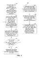
- FIG. 2 is a block diagram of a process for estimating battery characteristics including at least the open cell voltage of the battery during operation while the battery remains connected to a load.
- FIG. 3 is a schematic diagram of an equivalent circuit used in a battery model in the system of FIG. 1 .
- FIG. 4 is a schematic diagram of a cost optimization process that is implemented in the system 100 to determine the excitation level of the battery over time while the battery remains connected to a load.
- FIG. 5 is a graph depicting estimated battery capacity measurements that are generated using an embodiment of the system of FIG. 1 and the process of FIG. 2 .
- FIG. 6 is another graph depicting estimated battery capacity measurements that are generated using an embodiment of the system of FIG. 1 and the process of FIG. 2 .
- FIG. 7 is another graph depicting estimated battery capacity measurements that are generated using an embodiment of the system of FIG. 1 and the process of FIG. 2 .
- battery refers to an electrochemical energy storage device that provides electrical power to drive a load that operates using electrical energy.
- battery types include, but are not limited to, different forms of lithium-ion, lithium-polymer, nickel metal hydride, lead acid, and flow batteries.
- multiple battery cells constitute a larger battery.
- Each individual battery cell includes all of the structural elements (e.g. anode, cathode, and electrolyte) of a battery, but in many practical embodiments multiple battery cells are connected together with, for example, series, parallel, and series-parallel electrical connections to form a larger battery that has sufficient energy storage and power delivery capabilities to be used in a practical device.
- battery pack refers to practical embodiment of a battery that includes at least one battery cell and optionally additional sensor and control devices that are connected to the at least one battery cell.
- battery management system refers to an electronic control device that monitors the status of a battery using sensor data collected from the battery and, in some embodiments, models of the battery that enable the battery management system to estimate characteristics of the battery during operation.
- loads that receive electrical power from a battery include, but are not limited to, electronic circuits and digital computing devices, electrical motors, and electrical heating devices.
- a load that is used herein for illustrative purposes is an electric vehicle that typically includes at least one electrical drive motor as well as multiple secondary electrical motors (e.g. for power steering, windshield wipers, brakes, mirrors, windows, and for heating/cooling) along with various lights and analog and digital electronic devices.
- secondary battery which are also referred to as “rechargeable” batteries, certain types of loads provide electrical power to the battery to perform a recharging process.
- Loads that generate electrical power include, for example, any alternating current (AC) electrical power generation system (e.g.
- the term “state of health” refers to the available capacity of the battery between two specified voltage limits such as a maximum operating voltage when the battery is fully charged and a minimum operating voltage at which point the battery is considered to be discharged for operational purposes.
- SoH state of health
- the SoH does not necessarily correspond to the absolute maximum and minimum charge levels that are physically possible in the battery because overcharging and undercharging to the physical limits of the battery often results in shortened battery lifespan and damage to the battery.
- the SoH of a battery changes over time as the battery ages during use, with the SoH of most practical batteries experiencing a long-term decline over the life of the battery.
- the SoH value can increase or decrease based on various environmental factors and the usage pattern of the battery.
- the SoH characteristic is often referenced in units of energy, such as joules, watt-hours, or any other suitable energy unit, but those of skill in the art also often refer to SoH in units of amp-hours or other units of current and time since the battery is assumed to operate at some nominal voltage level.
- the SoH characteristic is described using a percentage value in which a 100% SoH corresponds to the total available capacity of the battery at time of manufacture and the SoH of the battery gradually reduces to lower percentage values during the life of the battery.
- the term “state of charge” refers to a ratio of the amount of charge that is stored in a battery at a given point during operation to a total charge that can be stored in the battery at a full charge level using the upper voltage limit for the SoH.
- the SoC changes as the battery is discharged and charged during operation.
- the SoC is also expressed as a fraction or percentage of the SoH for the battery since the SoC of a fully-charged battery is equal to the total SoH for the battery and the SoC decreases as the battery discharges.
- FIG. 1 is a schematic diagram of a battery system 100 that monitors the OCV and optionally SoC and SoH of a battery connected to a load.
- the battery system 100 includes a battery pack 104 that provides electrical power to a load 140 , a battery management system (BMS) controller 150 , which is also referred to as the “controller” 150 herein, and a user display device 180 .
- BMS battery management system
- FIG. 1 depicts the battery pack 104 and the battery management system 150 as separate elements, in some embodiments the BMS is physically integrated into the battery pack while in other embodiments a BMS is connected to one or more battery packs via a digital communication channel such as a controller area network (CAN) bus, universal serial bus, Ethernet, or any other suitable digital communication channel.
- CAN controller area network
- the battery pack 104 includes electrical terminals 108 A and 108 B, one or more battery cells 112 , a voltage sensor 116 , a current sensor 120 , and a temperature sensor 124 .
- the terminals 108 A and 108 B are electrically connected the battery cells 112 and the battery pack 104 is electrically connected to a load 140 via the terminals 108 A and 108 B to enable the battery pack 104 to provide electrical power to the load 140 .
- FIG. 1 depicts a load 140 that receives electrical power from the battery cells 112 in the battery pack 104
- the load 140 is replaced with an electrical power source that provides electrical power to the battery pack 104 to charge the battery cells 112 .
- the voltage sensor 116 measures a voltage potential of all of the battery cells 112 , which is depicted with a connection of the voltage sensor 116 to the terminals 108 A and 108 B of the battery pack 104 in FIG. 1 . If the battery pack 104 is disconnected from any load and allowed to return to a quiescent state then the voltage sensor 116 can measure the OCV of the battery cells 112 directly. However, during operation of the battery pack 104 to supply electrical current to the load 140 , the voltage sensor 116 does not measure the OCV of the battery cells 112 . The voltage sensor 116 does, however, produce voltage measurements that the controller 150 uses in conjunction with other sensor data to generate estimates of the OCV for the battery 112 cells as is further described below.
- the current sensor 120 measures a flow of electrical current through all of the battery cells 112 .
- the current sensor 120 is depicted as an ammeter that is connected in series with the battery cells 112 for illustrative purposes, but those of skill in the art will recognize that a shunt resistor, current clamp ammeter, or any other suitable indirect current sensing device is also suitable for use with the battery pack 104 .
- the temperature sensor 124 is a thermocouple, thermistor, or any other suitable temperature probe that is physically affixed to the battery cells 112 to generate measurements of the temperature of the battery cells 112 during operation. In some embodiments the temperature sensor 124 further includes multiple temperature sensing elements that measure the temperatures of different battery cells within a larger array of battery cells in larger battery pack configurations where the battery cells 112 may not have uniform temperatures.
- the controller 150 includes at least one digital logic device and at least one memory device.
- the controller 150 is operatively connected to the battery pack 104 and receives sensor data from the voltage sensor 116 , the current sensor 120 , and the temperature sensor 124 .
- the controller 150 is implemented using at least one microprocessor, microcontroller, field programmable gate array (FPGA), digital signal processor (DSP), application specific integrated circuit (ASIC), or other suitable digital logic devices.
- the controller 150 optionally includes analog to digital converters (ADCs) in embodiments where one or more of the sensors 116 - 124 generate analog sensing signals to enable the controller 150 to process digital representations of the analog sensor signals, although in other embodiments the sensors include ADC circuits that produce digital output data directly.
- ADCs analog to digital converters
- the memory in the controller 150 includes both a volatile data storage device such as a static or dynamic random access memory (RAM) and a non-volatile memory such as NOR and NAND flash or a magnetic disc that stores long-term data such as system software/firmware stored program instructions and default parameters for a battery model and other battery characteristics that are described below.
- a volatile data storage device such as a static or dynamic random access memory (RAM)
- a non-volatile memory such as NOR and NAND flash or a magnetic disc that stores long-term data such as system software/firmware stored program instructions and default parameters for a battery model and other battery characteristics that are described below.
- the controller 150 executes stored program instructions in the memory to implement a battery model 154 , battery state and parameter estimation logic 160 , and vehicle range or device remaining runtime logic 172 .
- the battery model 154 includes stored parameters for an equivalent circuit or electrochemical model that approximates the internal state of the battery cells 112 .
- the state and parameter estimation logic 160 uses the battery model 154 and input data from the voltage sensor 116 , current sensor 120 , and the temperature sensor 124 to generate estimates for the OCV with the OCV estimator 164 , the SoC with the SoC estimator 166 , and the SoH with the capacity estimator 168 .
- the vehicle range or device remaining runtime estimator 172 enables the controller 150 to use the estimated SoC and SoH characteristics of the battery cells 112 in the battery pack 104 in conjunction with the past, present, and predicted future power consumption characteristics of the load 140 to generate an estimate of the remaining useful capacity of the battery to drive the load.
- the range estimator 172 provides an estimate of the remaining driving range of the vehicle before the battery pack 104 needs to be recharged.
- the runtime estimator 172 provides an estimate of how much longer the device may operate until the battery pack 104 needs to be recharged.
- the BMS controller 150 is also connected to a user display device 180 which is, for example, an LCD display or an audio output device that generates an output based on the estimated OCV, SoC, and SoH of the battery cells 112 or an output corresponding to the estimated remaining vehicle range or device runtime.
- a user display device 180 which is, for example, an LCD display or an audio output device that generates an output based on the estimated OCV, SoC, and SoH of the battery cells 112 or an output corresponding to the estimated remaining vehicle range or device runtime.
- FIG. 3 depicts one embodiment of a battery model 300 .
- the battery model 300 is defined as an equivalent circuit that has the electrical properties of the battery cells 112 , including internal impedance and capacitance properties of the battery cells 112 .
- the equivalent circuit 300 includes a resistance R 0 ( 304 ) that is connected in series with a parallel connected combination of another resistance R 1 ( 308 ) and a capacitance C 1 ( 312 ).
- the equivalent circuit 300 also includes a variable voltage source 316 that represents the voltage level that the battery produces at different SoC levels. Hence, the output voltage of the voltage source 316 is represented by a function ⁇ where the output of ⁇ is a voltage level that depends on the SoC at a time t during operation of the battery.
- the function ⁇ is embodied as a lookup table or other curve in the SoC estimator 166 for use in determining an estimate of SoC after the system 100 has generated an accurate estimate of the OCV.
- the function ⁇ is a mapping between OCV and SoC is determined empirically by testing ⁇ the voltage levels of the battery cells 112 at various SoC levels at the time of manufacture of the battery 112 and in some embodiments the mapping between OCV and SoC changes gradually over the lifetime of the battery pack 104 , although during the timeframe of the process 200 the mapping remains fixed.
- the voltage V(t) ( 324 ) represents the total output voltage of the battery that varies over time based on the voltage level of the voltage source 316 and the changes in voltage that occur due to the current flow through the resistors R 0 , R 1 and the effects of the capacitor C 1 .
- the output voltage V(t) 324 is equal to the voltage level of the voltage source 316 based on the current SoC of the battery using the predetermined function ⁇ (SoC(t)).
- the controller 150 uses the battery model 154 to identify estimated OCV values for the actual battery cells 112 while the battery cells 112 provide current to the load 140 .
- FIG. 2 depicts a process 200 for monitoring a battery while the battery is connected to a load to enable the estimation of battery characteristics including at least the OCV and optionally the SoC and SoH in the battery without having to disconnect the battery from the load.
- a reference to the process 200 performing a function or action refers to the operation of a controller, such as the controller 150 in the system 100 , to execute stored program instructions to perform the function or action in conjunction with other components in the battery management system and battery pack.
- Process 200 begins as the battery pack 104 provides electrical current to drive the load 140 and the controller 150 receives sensor data including measurements of the voltage level across the terminals 108 A and 108 B from the voltage sensor 116 , the current level flowing through the battery pack 104 to the load from the current sensor 120 , and temperature level data for the battery cells 112 from the temperature sensor 124 (block 204 ). While FIG. 2 depicts the block 204 at the beginning of the block diagram, the controller 150 continues to receive the sensor data from the sensors in the battery pack 104 at regular intervals throughout the operation of the battery pack 104 .
- the process 200 continues as the controller 150 uses the measured voltage level from the voltage sensor 116 (V(t)) and measured current level data from the current sensor (I(t) at a particular time t to generate an initial estimate of the OCV for the battery 112 based on the battery model 154 that includes the resistance values R 0 and R 1 and the capacitance value C 1 described above.
- V(t) the output voltage V(t) is provided by the following equations, where I 1 is the current through the resistance R 1 :
- ⁇ (SOC(t)) provides the voltage of the voltage source 316 based on the function ⁇ and the SoC at time t.
- I(t)R 0 +I 1 (t)R 1 correspond to V polarization since these terms represent the combined voltage drops across the resistors R 0 and R 1 in the equivalent circuit 300 as current flows through the circuit and represent the deviation of the battery terminal voltage from the steady state voltage.
- the controller 150 uses the battery model parameters (R 0 ,R 1 ,C 1 ), which correspond to the internal impedance of the actual battery cells 112 , to generate an accurate estimate of the OCV of the battery cells 112 .
- the estimation of the impedance parameters relies first on a reformulation of the equivalent circuit model dynamics in to an input output model where the output depends linearly on the impedance parameters. Regression techniques can then be applied to this input output model to estimate the impedance parameters.
- the controller 150 identifies the values of V(t) and (I(t)R 0 +I 1 (t)R 1 ) directly from the sensor data and the resistance values in the equivalent circuit 300 of the battery model 154 to identify the estimated OCV: ⁇ circumflex over (V) ⁇ OCV (t).
- the “ ⁇ ” notation indicates that a value in an equation is an estimate rather than a value that is determined directly from sensor input or other precise values. While an estimate of OCV can be obtained simply from the mapping ⁇ and an estimate of SoC, this direct approach leads to inaccurate capacity estimation as the error in SoC estimation propagates to the capacity estimation. Since errors in capacity estimation significantly affect the SoC estimation, this effect propagates further and could result in poor estimation of the battery capacity.
- the estimated OCV ⁇ circumflex over (V) ⁇ OCV (t) may be inaccurate since the value is determined using the equivalent battery model 154 that may not fully account for all possible transient current and voltage values that are measured during operation of the battery pack 104 . If the actual battery cells 112 have a high excitation level at the time that the OCV is estimated using the battery model 154 , then the estimated OCV may be inaccurate even if the battery model 154 would provide an accurate estimate of OCV when the battery cells 112 are operating in a steady state with a low excitation level.
- Process 200 continues as the controller 150 uses a cost optimization process to determine an excitation level J of the battery cells 112 at or around the time that the OCV was estimated during the operation of the battery pack 104 (block 212 ).
- FIG. 4 is a graphical depiction of the cost optimization process 400 in more detail.
- the controller 150 executes the cost optimization process 400 using stored program instructions in the OCV estimator 164 using input sensor data from the battery pack 104 .
- the cost optimization process 400 receives as inputs multiple samples of sensor data from each of the sensors in the battery pack 104 including the measured battery voltage V(t) 404 from the voltage sensor 116 , measured current I(t) from the current sensor 120 , and measured temperature data T(t) 412 from the temperature sensor 124 .
- the optimization process 400 also implements filters 420 that produce measurements of the changes in the voltage, current, and temperature sensor data over time, which are expressed mathematically as the derivatives of voltage
- the filters 420 generate the derivatives by performing a linear curve-fitting process through a plurality of sensor data samples that are received over a predetermined time period (e.g. a time span of 30 seconds).
- the controller 150 identifies the slopes of the fitted curves as the instantaneous rate of change of each sensor value at the measurement time t, which are expressed as the derivatives of voltage
- the filters 420 use averaging of multiple sensor values over time and filter implementations with appropriately tuned filter cutoff parameters including, for example, a series of Chebyshev or Butterworth filters that are known to the art to reduce or eliminate the effects of random noise that occurs in individual sensor data samples when determining the rates of change for the voltage, current, and temperature data.
- the cost optimization process 400 also receives predetermined threshold values ⁇ 1 , ⁇ 2 , ⁇ 3 , ⁇ 4 416 that correspond to thresholds for the current input I(t) 408 , current derivative
- the cost optimization process 400 implements a cost function 432 that generates a measurement of the excitation level J of the battery cells 412 that minimizes an error (cost) between the excitation level J and the observed input data given the predetermined threshold values 416 .
- the cost function 432 is:
- J ⁇ ( t ) f ⁇ ( I ⁇ ( t ) , dI dt , dV dt , dT dt , ⁇ 1 , ⁇ 2 , ⁇ 3 , ⁇ 4 )
- the cost function 432 produces a four element vector based on the quotients of the measured current I(t) and the derivatives of current, voltage, and temperature divided by the predetermined thresholds:
- the output of the cost function 432 is a battery excitation level parameter J corresponding to the battery cells 112 in the battery pack 104 at the same time t that the process 200 generates the estimate of the OCV, although those of skill in the art will recognize that in a practical embodiment the OCV estimate and the battery excitation level estimate can be generated within a predetermined time window (e.g. within a span of 5 seconds of operation of the battery pack 104 ) and need not both correspond to a single instant in time.
- the controller 150 generates the estimates of OCV and the battery excitation level Jas described with reference to blocks 208 and 212 in any order or concurrently.
- the battery excitation level J is a signal that the controller 150 measures to identify a deviation of the battery from a steady state condition.
- the controller 150 uses the zero cost to indirectly identify that the battery cells 112 are not experiencing concentration gradients or thermal gradients that produce transient conditions in the battery cells 112 that could lead to errors in estimating the OCV using the predetermined battery model 154 . Consequently the magnitude of J at any time indicates a distance of the battery state to this equilibrium condition.
- the predetermined threshold values ⁇ 1 , ⁇ 2 , ⁇ 3 , ⁇ 4 enable the controller 150 to identify pseudo-equilibrium scenarios when the estimate of the OCV of the battery obtained from an equivalent circuit model is accurate even if the battery is not completely at equilibrium.
- the controller 150 does not use the estimated OCV in any further processing since the excitation level of the battery means the OCV estimate has high likelihood of being inaccurate.
- the process 200 continues as the sensors in the battery pack 104 generate additional sensor data while the battery pack 104 provides electrical current to drive the load 140 (block 220 ) and the controller 150 repeats the processing that is described above with reference to blocks 208 - 216 until the controller 150 determines an estimated OCV for the battery pack 104 that occurs while the excitation level J of the battery pack 104 is below the predetermined threshold to ensure that the estimated OCV has sufficient accuracy to be used in generating further estimates of the SoC and SoH of the battery.
- the controller 150 in the embodiment of FIG. 1 can continue to perform the OCV estimation process continuously during operation of the battery pack 104 to produce updated estimates for the OCV of the battery pack 104 at different times during operation of the system 100 .
- the controller 150 generates multiple SoC estimates for the battery at different times during operation, and the controller 150 continues to generate OCV estimates at the different times to enable more accurate generation of the SoC estimates.
- the process 200 continues as the system 100 identifies an estimated SoC of the battery cells 112 in the battery pack 104 at time t (block 224 ).
- the controller 150 stores multiple SoC estimates that are generated at different times t using the estimated OCV values at the different times tin the memory to track the changes in SoC levels in the battery pack 104 as the battery cells 112 deliver power to the load 140 .
- the controller 150 also identifies the ⁇ SoC, which refers to the change in the SoC level that occurs over time, such as the change in SoC from a first time t 1 to a second time t 2 although the ⁇ SoC can also refer to changes of the SoC over three or more different points in time.
- the ⁇ SoC refers to the change in the SoC level that occurs over time, such as the change in SoC from a first time t 1 to a second time t 2 although the ⁇ SoC can also refer to changes of the SoC over three or more different points in time.
- the controller 150 optionally uses the measured changes ⁇ SoC and measurements of the current flow through the battery over time during operation of the battery pack 104 to generate estimates of the SoH of the battery cells 112 while the battery pack 104 drives the load 140 (block 228 ).
- the controller 150 uses the capacity estimator 168 to combine multiple measurements of changes in the SoC over time with a process that is referred to as “Coulomb counting” referring to the total amount of charge that the battery pack 104 delivers to the load 140 over time to estimate the total capacity of the battery cells 112 at different times.
- the controller 150 identifies the accumulated charge by summing the current level measurement values that are received from the current sensor 120 between the times t 1 to t 2 to identify the accumulated charge as a value in units of Coulombs or an equivalent charge unit.
- the current measurement values which are often expressed using Amps as a unit, refer to the rate at which charge moves in a circuit.
- the controller 150 sums the rate measurements over time to implement a numeric integration process that identifies the total accumulated charge over the time span from t 1 to t 2 .
- the SoH is related to ⁇ SoC and the accumulated charge based on the following equation:
- SoH 1 ⁇ ⁇ ⁇ SoC * ⁇ t 1 t 2 ⁇ I ⁇ ( ⁇ ) ⁇ d ⁇ ⁇ ⁇
- the parameter ⁇ represents the SoH of the battery.
- the SoH estimation process generally requires multiple sets of ⁇ SoC and accumulated charge data to produce accurate estimates of the battery SoH.
- the capacity estimator 168 in the controller 150 estimates the parameter ⁇ using one or more of a Least squares method, Extended Kalman Filter, Moving Horizon Estimator or Recursive Least Square (RLS) method.
- RLS Recursive Least Square algorithm
- the controller 150 executes stored program instructions to implement the RLS algorithm above or another variation of an SoH estimation process.
- the process 200 ensures that the controller 150 only generates the OCV events at times when the charge excitation level of the battery is sufficiently low to enable the OCV estimator 164 to produce accurate OCV estimates. Since both the SoC and SoH estimation processes rely upon accurate OCV inputs, the process 200 enables accurate estimations of SoC and SoH while the battery pack 104 remains connected to the load 140 during dynamic operation.
- Battery management systems use SoH in a wide range of operations.
- One operation that benefits from an accurate SoH estimate occurs as the controller 150 to operates the battery pack 104 in situations where the load 140 both receives power from the battery pack and charges the battery pack 104 at different times during operation.
- Examples of such system configurations include hybrid vehicles or power storage systems where the battery pack 104 receives a charging current and provides a power current at different times during operation.
- the system 100 generates an output that includes one or more of the estimated OCV, SoC, and SoH values for the battery cells 112 in the battery pack 104 and optionally additional information related to the battery state such as an estimate of remaining vehicle range or runtime of the load 140 (block 232 ).
- the controller 150 generates a visual display including alphanumeric or graphical representations of the battery and device status, or an audible output of the status of the battery cells 112 in the battery pack 104 using the user display device 180 .
- the user display device 180 can display the current estimated OCV as a voltage value, the SoC as a percentage value or a graphical battery level icon, and the SoH as a numeric capacity value or as a percentage of the nominal capacity of the battery pack 104 at time of manufacture.
- the controller 150 optionally performs additional vehicle range/device remaining runtime estimation 172 that uses the generated information about the battery SoC and SoH in conjunction with a forecast of the energy usage patterns of the load 140 to generate an output that informs the user of, for example, the estimated remaining range of an electric vehicle or an estimated remaining time that a device such as a smartphone or other electronic device may run until the battery reaches a minimum operational charge level.
- the display device 180 is further configured to produce visual or audible outputs to alert operators to the remaining estimated vehicle range or device runtimes.
- the controller 150 performs the process 200 continuously while the battery pack 104 is connected to the load 140 to produce continuous updates the estimated OCV and to generate corresponding updates to the SoC and SoH as the OCV changes during the operation of the battery pack 104 .
- the controller 150 then generates updated outputs with the display device 180 or another output device to provide updates to the status of the battery cells 112 and optionally to display the current status and usage history of the battery cells 112 .
- the embodiments described herein provide technological improvements to devices that use batteries to provide electrical power to various loads.
- the system 100 of FIG. 1 and the process 200 of FIG. 2 enable accurate estimation of the OCV level of the battery cells 112 while the battery pack 104 remains connected to the load 140 during continuous operation without requiring the battery pack 104 to be disconnected from the load 140 to enable direct measurement of the OCV in the quiescent state.
- enabling high accuracy for the estimation of OCV also improves the accuracy of estimation of SoC and SoH to enable the system 100 to accurately monitor the battery pack 104 while the battery pack 104 remains connected to the load 140 .
- FIG. 5 - FIG. 7 depict graphs of the SoH estimates that are generated in one practical embodiment of the system 100 that performs the process 200 to estimate the OCV, SoC, and SoH levels of a battery while the battery provides electrical power to a load.
- FIG. 5 depicts a graph 500 of the SoH estimates (measured in units of amp-hours Ah) for a battery over an extended series of charge and discharge operations over a period of approximately 2,500 hours of operation.
- the total capacity generally decreases over time, which is expected as the battery ages, and the system 100 can generate accurate estimates of the SoH for the battery even in the presence of noise in the measurement data from sensors in the battery pack.
- FIG. 5 depicts a graph 500 of the SoH estimates (measured in units of amp-hours Ah) for a battery over an extended series of charge and discharge operations over a period of approximately 2,500 hours of operation.
- the total capacity generally decreases over time, which is expected as the battery ages, and the system 100 can generate accurate estimates of the SoH for the battery
- FIG. 6 depicts a similar graph 600 that includes a more detailed view 650 of the SoH estimates for the battery when the battery is still new and there is minimal historical information about changes in SoC and charge to use in generating estimates for the SoH.
- the system 100 performs the process 200 to converge to an accurate estimate of the SoH within a few hours of the operational life of the battery.
- FIG. 7 depicts another graph 700 of the SoH estimates for a battery that the system 100 generates using the process 200 .
- FIG. 7 depicts accurate SoH estimates that are generated with both the presence of noise in the sensor data and in the presence of a systemic measurement bias that may occur in certain embodiments of the voltage sensor 116 and current sensor 120 in the battery pack 104 . As depicted in the graph 700 , the system 100 still generates accurate SoH estimates even in the presence of measurement noise and bias.
Landscapes
- Physics & Mathematics (AREA)
- General Physics & Mathematics (AREA)
- Engineering & Computer Science (AREA)
- Manufacturing & Machinery (AREA)
- Chemical & Material Sciences (AREA)
- Chemical Kinetics & Catalysis (AREA)
- Electrochemistry (AREA)
- General Chemical & Material Sciences (AREA)
- Secondary Cells (AREA)
Abstract
Description
current
and temperature
with respect to time t. In one practical embodiment the
current
and temperature
in
voltage derivative
and temperature derivative
respectively. The
The
Accumulated Charge=∫t
In the embodiment of
The above equation can be rewritten in an input output format with the output y representing the accumulated charge and the input x represents the change in SoC. The parameter θ represents the SoH of the battery.
Accumulated Charge=SoH*(ΔSoC) y=θx.
The SoH estimation process generally requires multiple sets of ΔSoC and accumulated charge data to produce accurate estimates of the battery SoH. The
where α∈[0,1] is the forgetting factor and P0 is the initial value of the uncertainty matrix. The
Claims (16)
Priority Applications (4)
| Application Number | Priority Date | Filing Date | Title |
|---|---|---|---|
| US15/664,814 US10312699B2 (en) | 2017-07-31 | 2017-07-31 | Method and system for estimating battery open cell voltage, state of charge, and state of health during operation of the battery |
| PCT/EP2018/069230 WO2019025171A1 (en) | 2017-07-31 | 2018-07-16 | Method and system for estimating battery open cell voltage, state of charge, and state of health during operation of the battery |
| CN201880049746.8A CN110914696B (en) | 2017-07-31 | 2018-07-16 | Method and system for estimating battery open cell voltage, state of charge, and state of health during operation of a battery |
| DE112018000281.0T DE112018000281T5 (en) | 2017-07-31 | 2018-07-16 | A method and system for estimating a cell idle voltage, a state of charge, and a health status of a battery during operation of the battery |
Applications Claiming Priority (1)
| Application Number | Priority Date | Filing Date | Title |
|---|---|---|---|
| US15/664,814 US10312699B2 (en) | 2017-07-31 | 2017-07-31 | Method and system for estimating battery open cell voltage, state of charge, and state of health during operation of the battery |
Publications (2)
| Publication Number | Publication Date |
|---|---|
| US20190036356A1 US20190036356A1 (en) | 2019-01-31 |
| US10312699B2 true US10312699B2 (en) | 2019-06-04 |
Family
ID=63047310
Family Applications (1)
| Application Number | Title | Priority Date | Filing Date |
|---|---|---|---|
| US15/664,814 Active US10312699B2 (en) | 2017-07-31 | 2017-07-31 | Method and system for estimating battery open cell voltage, state of charge, and state of health during operation of the battery |
Country Status (4)
| Country | Link |
|---|---|
| US (1) | US10312699B2 (en) |
| CN (1) | CN110914696B (en) |
| DE (1) | DE112018000281T5 (en) |
| WO (1) | WO2019025171A1 (en) |
Cited By (10)
| Publication number | Priority date | Publication date | Assignee | Title |
|---|---|---|---|---|
| TWI737021B (en) * | 2019-10-23 | 2021-08-21 | 國立中山大學 | Control method of energy storage system |
| US11462749B2 (en) | 2019-12-31 | 2022-10-04 | Robert Bosch Gmbh | Fuel cell device and systems enabling cell-level repair |
| US11515587B2 (en) * | 2019-10-10 | 2022-11-29 | Robert Bosch Gmbh | Physics-based control of battery temperature |
| US11543460B2 (en) * | 2019-09-12 | 2023-01-03 | Samsung Electronics Co., Ltd. | Battery state measuring method and battery management system |
| US20230039331A1 (en) * | 2021-08-05 | 2023-02-09 | Samsung Sdi Co., Ltd. | Method and apparatus for calculating relative state-of-charge of battery |
| US11835583B1 (en) | 2022-05-11 | 2023-12-05 | Univerza V Ljubljani | Computer-implemented method for diagnosing states of a battery |
| US12049398B1 (en) | 2023-08-16 | 2024-07-30 | Crown Equipment Corporation | Materials handling and other vehicles with functional responses to runtime calculation |
| US12081060B2 (en) | 2020-09-11 | 2024-09-03 | Robert Bosch Gmbh | Minimizing irreversible swelling during battery charging |
| DE102023202789A1 (en) | 2023-03-27 | 2024-10-02 | Robert Bosch Gesellschaft mit beschränkter Haftung | Method and device for providing suitable charging profiles for device batteries of battery-operated devices |
| DE102023213289A1 (en) * | 2023-12-22 | 2025-07-10 | Robert Bosch Gesellschaft mit beschränkter Haftung | Method and device for predictive operation of a device battery with a power supply network |
Families Citing this family (47)
| Publication number | Priority date | Publication date | Assignee | Title |
|---|---|---|---|---|
| KR102035679B1 (en) * | 2016-11-29 | 2019-10-23 | 주식회사 엘지화학 | Method and system for caculating state of health(soh) of a battery |
| CN107390138B (en) * | 2017-09-13 | 2019-08-27 | 山东大学 | A New Method for Iterative Identification of Parameters of Power Battery Equivalent Circuit Model |
| KR102179684B1 (en) * | 2017-09-29 | 2020-11-17 | 주식회사 엘지화학 | Apparatus and method for calculating battery pack SOH |
| KR102515606B1 (en) * | 2017-10-31 | 2023-03-28 | 삼성에스디아이 주식회사 | Method, battery pack, and electronic device for displaying battery charge capacity |
| US20190170826A1 (en) * | 2017-12-06 | 2019-06-06 | Cadex Electronics Inc. | Battery state-of-health determination upon charging |
| CN111971869B (en) * | 2018-03-16 | 2024-08-13 | 道达尔太阳能国际公司 | Systems, devices and methods for off-grid microgrid management |
| CN108845270B (en) * | 2018-07-11 | 2021-01-05 | 国网江西省电力有限公司电力科学研究院 | Estimation method of life cycle cost of lithium iron phosphate power battery cascade utilization |
| CN112470315B (en) * | 2018-07-30 | 2024-01-09 | 住友电气工业株式会社 | Redox flow battery system |
| DE102018217665A1 (en) * | 2018-10-16 | 2020-04-16 | Robert Bosch Gmbh | Method and system for operating electrical energy stores |
| DE102019103144B4 (en) | 2019-02-08 | 2020-10-15 | Infineon Technologies Ag | Device and method for monitoring the reliability of a cell impedance measurement of a battery cell |
| US10908219B2 (en) | 2019-05-20 | 2021-02-02 | Robert Bosch Gmbh | Battery management system with mixed electrode |
| CN113075555B (en) * | 2019-05-24 | 2024-08-23 | 宁德时代新能源科技股份有限公司 | SOC correction method and device, battery management system and storage medium |
| EP3751299B1 (en) | 2019-06-11 | 2023-08-09 | Volvo Car Corporation | Detecting latent faults within a cell of an energy storage system |
| FR3097649B1 (en) | 2019-06-20 | 2021-06-18 | Commissariat Energie Atomique | Method for determining a robust estimator of the capacity of an electric battery |
| KR102871577B1 (en) * | 2019-09-04 | 2025-10-17 | 삼성전자주식회사 | Method and apparatus charging battery |
| DE102019216306A1 (en) * | 2019-10-23 | 2021-04-29 | Robert Bosch Gmbh | Method for determining parameters of an electrochemical energy store of an electrically drivable vehicle |
| FR3104728B1 (en) * | 2019-12-11 | 2021-12-10 | Electricite De France | Diagnosis of energy storage systems in operation |
| DE102019134436A1 (en) * | 2019-12-16 | 2021-06-17 | Bayerische Motoren Werke Aktiengesellschaft | Method and device for estimating the usable charge capacity of an electrical energy store |
| ES2739535B9 (en) * | 2019-12-18 | 2020-12-02 | Garcia Luis Arturo Parres | METHOD AND SYSTEM TO CALCULATE THE ENERGY AVAILABLE IN AN ELECTRIC BATTERY AT ANY TIME IN ITS LIFE. WITHOUT DOWNLOADING IT, AS WELL AS ITS AUTONOMY, CAPACITY. AND LIFE REMAINING |
| US11181586B2 (en) * | 2020-01-15 | 2021-11-23 | Medtronic, Inc. | Model-based capacity and resistance correction for rechargeable battery fuel gauging |
| CN115968447A (en) | 2020-05-07 | 2023-04-14 | 齐塔拉科技公司 | Battery analysis system and method |
| CN111707954A (en) * | 2020-06-18 | 2020-09-25 | 中汽研汽车检验中心(天津)有限公司 | A kind of lithium iron phosphate power battery life prediction method |
| TWI758760B (en) * | 2020-06-24 | 2022-03-21 | 仁寶電腦工業股份有限公司 | Battery control device and battery capacity estimation method |
| US20230236251A1 (en) * | 2020-07-08 | 2023-07-27 | Panasonic Intellectual Property Management Co., Ltd. | Arithmetic system, battery inspection method, and battery inspection program |
| EP4209794A4 (en) * | 2020-09-04 | 2024-06-19 | Kabushiki Kaisha Toshiba | INFORMATION PROCESSING DEVICE, INFORMATION PROCESSING METHOD, INFORMATION PROCESSING SYSTEM AND PROGRAM |
| DE102021105784A1 (en) | 2021-03-10 | 2022-09-15 | TWAICE Technologies GmbH | Estimation of parameters for rechargeable batteries |
| CN113433473A (en) * | 2021-05-25 | 2021-09-24 | 东风柳州汽车有限公司 | Method and device for detecting capacity retention rate of battery |
| CN113447826B (en) * | 2021-09-01 | 2021-11-16 | 蜂巢能源科技有限公司 | A SOC determination method and device based on steady state equivalent circuit model |
| US11774504B2 (en) * | 2021-10-04 | 2023-10-03 | Zitara Technologies, Inc. | System and method for battery management |
| CN114084026B (en) * | 2021-11-29 | 2023-06-02 | 重庆长安新能源汽车科技有限公司 | Dynamic programming method and system for optimal charging path of electric automobile |
| CN114325404B (en) * | 2021-12-09 | 2023-09-26 | 重庆大学 | A battery temperature estimation method based on thermal-neural network coupling model |
| EP4409309A4 (en) | 2021-12-09 | 2025-10-22 | Zitara Tech Inc | System and method for determining a battery condition |
| CN114123430A (en) * | 2021-12-20 | 2022-03-01 | 成都康斯维智慧能源技术有限公司 | Intelligent grouping management device powered by multi-branch battery pack and control method |
| EP4206709A1 (en) * | 2021-12-28 | 2023-07-05 | Nanjing Chervon Industry Co., Ltd. | State of charge estimation method |
| FR3132150B1 (en) * | 2022-01-27 | 2024-04-12 | Psa Automobiles Sa | RELIABLE ESTIMATION OF THE STORAGE CAPACITY OF CELL(S) OF A CELLULAR BATTERY |
| DE102022113179A1 (en) | 2022-05-25 | 2023-11-30 | Webasto SE | Method and system for operating an energy storage device with a plurality of battery cells |
| US20230393217A1 (en) * | 2022-06-03 | 2023-12-07 | TotalEnergies OneTech SAS | State-of-health estimation pipeline for li-ion battery packs with heterogeneous cells |
| CN115092012B (en) * | 2022-07-20 | 2024-04-12 | 四川轻化工大学 | Equivalent state of charge estimation method considering multiple operating modes of composite power system |
| CN115598535B (en) * | 2022-09-30 | 2025-05-09 | 西安交通大学 | A battery state of charge estimation method and system considering health status |
| DE102022126573A1 (en) * | 2022-10-12 | 2024-04-18 | Webasto SE | Device for measuring a temperature in a battery, battery module, battery and motor vehicle |
| CN115566236B (en) * | 2022-12-05 | 2023-03-24 | 广东电网有限责任公司江门供电局 | Battery energy storage system operation control method, device, equipment and medium |
| CN116430260A (en) * | 2023-03-17 | 2023-07-14 | 武汉动力电池再生技术有限公司 | Lithium battery SOH estimation method, device, electronic equipment and storage medium |
| DE102023206141A1 (en) * | 2023-06-29 | 2025-01-02 | Robert Bosch Gesellschaft mit beschränkter Haftung | Method for decelerating a servo motor of a steering device |
| CN116643178B (en) * | 2023-07-27 | 2023-09-22 | 深圳凌奈智控有限公司 | SOC estimation method and related device of battery management system |
| WO2025081058A1 (en) | 2023-10-11 | 2025-04-17 | Zitara Technologies, Inc. | System and method for degradation based battery control |
| CN117341976B (en) * | 2023-12-05 | 2024-02-02 | 合肥德智航创科技有限公司 | Comprehensive health management system of unmanned aerial vehicle |
| CN120999851B (en) * | 2025-10-24 | 2026-02-27 | 北京迅巢科技有限公司 | Multi-objective charging strategy optimization method considering battery health degradation |
Citations (7)
| Publication number | Priority date | Publication date | Assignee | Title |
|---|---|---|---|---|
| EP1220413A1 (en) | 1999-09-09 | 2002-07-03 | Toyota Jidosha Kabushiki Kaisha | Apparatus for battery capacity measurement and for remaining capacity calculation |
| US20060284600A1 (en) | 2005-06-21 | 2006-12-21 | Verbrugge Mark W | Method for control and monitoring using a state estimator having variable forgetting factors |
| US7726975B2 (en) | 2006-06-28 | 2010-06-01 | Robert Bosch Gmbh | Lithium reservoir system and method for rechargeable lithium ion batteries |
| US20110156713A1 (en) | 2009-12-25 | 2011-06-30 | Primearth Ev Energy Co., Ltd. | Apparatus for calculating polarization voltage of secondary battery and apparatus for estimating state of charge of the same |
| US20110309838A1 (en) | 2010-06-22 | 2011-12-22 | Gm Global Technology Operations, Inc. | Adaptive battery parameter extraction and soc estimation for lithium-ion battery |
| US20120109433A1 (en) | 2010-10-28 | 2012-05-03 | GM Global Technology Operations LLC | Systems and methods for determining the target thermal conditioning value to control a rechargeable energy storage system |
| US20130311115A1 (en) | 2012-05-16 | 2013-11-21 | Robert Bosch Gmbh | Battery System and Method with Parameter Estimator |
Family Cites Families (14)
| Publication number | Priority date | Publication date | Assignee | Title |
|---|---|---|---|---|
| AU2011316798B2 (en) * | 2010-10-22 | 2017-02-02 | Nucleus Scientific, Inc. | Apparatus and method for rapidly charging batteries |
| US8560257B2 (en) * | 2010-11-29 | 2013-10-15 | GM Global Technology Operations LLC | Dynamic battery capacity estimation |
| US9013143B2 (en) * | 2012-03-09 | 2015-04-21 | GM Global Technology Operations LLC | Method for charging a plug-in electric vehicle |
| CN103020445B (en) * | 2012-12-10 | 2016-07-06 | 西南交通大学 | A kind of SOC and SOH Forecasting Methodology of electric-vehicle-mounted ferric phosphate lithium cell |
| CN103454592B (en) * | 2013-08-23 | 2016-05-11 | 中国科学院深圳先进技术研究院 | A kind of method for estimating charge state of power cell and system |
| US20150219726A1 (en) * | 2014-02-03 | 2015-08-06 | GM Global Technology Operations LLC | Systems and methods for battery state estimation |
| US20160006275A1 (en) * | 2014-07-01 | 2016-01-07 | Ford Global Technologies, Llc | System and method for battery open circuit voltage estimation |
| CN104614676B (en) * | 2015-01-07 | 2017-09-29 | 王金全 | Consider the equivalent-circuit model modeling method of energy-storage battery pulse current response characteristic |
| CN104849672B (en) * | 2015-05-27 | 2017-09-15 | 中国人民解放军国防科学技术大学 | Lithium battery motional impedance parameter identification method based on equivalent-circuit model |
| CN105093128A (en) * | 2015-08-31 | 2015-11-25 | 山东智洋电气股份有限公司 | Storage battery state of charge (SOC) estimation method based on extended Kalman filtering (EKF) |
| CN105891727B (en) * | 2016-06-13 | 2018-10-19 | 桂林电子科技大学 | A kind of method of estimation and system of the power battery charged state of double structure changes filtering |
| JP6326452B2 (en) * | 2016-06-15 | 2018-05-16 | 本田技研工業株式会社 | Battery state estimation device and battery state estimation method |
| CN106324521B (en) * | 2016-09-05 | 2018-09-11 | 北京理工大学 | A kind of method of Combined estimator electrokinetic cell system parameter and state-of-charge |
| CN106443459A (en) * | 2016-09-06 | 2017-02-22 | 中国第汽车股份有限公司 | Evaluation method of state of charge of vehicle lithium ion power battery |
-
2017
- 2017-07-31 US US15/664,814 patent/US10312699B2/en active Active
-
2018
- 2018-07-16 DE DE112018000281.0T patent/DE112018000281T5/en active Pending
- 2018-07-16 CN CN201880049746.8A patent/CN110914696B/en active Active
- 2018-07-16 WO PCT/EP2018/069230 patent/WO2019025171A1/en not_active Ceased
Patent Citations (7)
| Publication number | Priority date | Publication date | Assignee | Title |
|---|---|---|---|---|
| EP1220413A1 (en) | 1999-09-09 | 2002-07-03 | Toyota Jidosha Kabushiki Kaisha | Apparatus for battery capacity measurement and for remaining capacity calculation |
| US20060284600A1 (en) | 2005-06-21 | 2006-12-21 | Verbrugge Mark W | Method for control and monitoring using a state estimator having variable forgetting factors |
| US7726975B2 (en) | 2006-06-28 | 2010-06-01 | Robert Bosch Gmbh | Lithium reservoir system and method for rechargeable lithium ion batteries |
| US20110156713A1 (en) | 2009-12-25 | 2011-06-30 | Primearth Ev Energy Co., Ltd. | Apparatus for calculating polarization voltage of secondary battery and apparatus for estimating state of charge of the same |
| US20110309838A1 (en) | 2010-06-22 | 2011-12-22 | Gm Global Technology Operations, Inc. | Adaptive battery parameter extraction and soc estimation for lithium-ion battery |
| US20120109433A1 (en) | 2010-10-28 | 2012-05-03 | GM Global Technology Operations LLC | Systems and methods for determining the target thermal conditioning value to control a rechargeable energy storage system |
| US20130311115A1 (en) | 2012-05-16 | 2013-11-21 | Robert Bosch Gmbh | Battery System and Method with Parameter Estimator |
Non-Patent Citations (9)
| Title |
|---|
| Chaturvedi et al., "Algorithms for Advanced Battery-Management Systems," IEEE Control Systems Magazine, 2010, pp. 49-68, vol. 30, No. 3, U.S. (20 pages). |
| Dai et al., "Online SOC Estimation of High-power Lithium-ion Batteries used on HEV's," Vehicular Electronics and Safety, International Converence Vehicular Electronics and Safety, 2006, pp. 1-6, China P.R. (6 pages). |
| International Search Report and Written Opinion for Corresponding Application (i.e., PCT/US2013/041362), dated Sep. 16, 2013 (9 pages). |
| International Search Report corresponding to International Patent Application No. PCT/EP2018/069230 (5 pages). |
| Lee et al., "Li-ion battery SOC estimation method based on the reduced order extended Kalman filtering," Journal of Power Sources, 2007, pp. 9-15, vol. 174, Republic of Korea (7 pages). |
| Piller et al., "Methods for state-of-charge determination and their applications," Journal of Power Sources, 2001, pp. 113-120, vol. 96, U.S. (8 pages). |
| Plett et al., "Extended Kalman filtering for battery management systems of LiPB-based HEV battery packs Part 3. State and parameter estimation," Journal of Power Sources, 2004, pp. 277-292, vol. 134, U.S. (16 pages). |
| Plett et al., "Sigma-point Kalman filtering for battery management systems of LiPB-based HEV battery packs Part 2: Simultaneous state and parameter estimation," Journal of Power Sources, 2006, pp. 1369-1384, vol. 161, U.S. (16 pages). |
| Roscher et al., "Dynamic electric behavior and open-circuit-voltage modeling of LiFePO4-based lithium ion secondary batteries," Journal of Power Sources, 2011, pp. 331-336, vol. 196, Germany (6 pages). |
Cited By (13)
| Publication number | Priority date | Publication date | Assignee | Title |
|---|---|---|---|---|
| US11543460B2 (en) * | 2019-09-12 | 2023-01-03 | Samsung Electronics Co., Ltd. | Battery state measuring method and battery management system |
| US11515587B2 (en) * | 2019-10-10 | 2022-11-29 | Robert Bosch Gmbh | Physics-based control of battery temperature |
| TWI737021B (en) * | 2019-10-23 | 2021-08-21 | 國立中山大學 | Control method of energy storage system |
| US12562392B2 (en) | 2019-12-31 | 2026-02-24 | Robert Bosch Gmbh | Method of monitoring and replacing fuel cell stacks within a fuel cell stack assembly |
| US11462749B2 (en) | 2019-12-31 | 2022-10-04 | Robert Bosch Gmbh | Fuel cell device and systems enabling cell-level repair |
| US12081060B2 (en) | 2020-09-11 | 2024-09-03 | Robert Bosch Gmbh | Minimizing irreversible swelling during battery charging |
| US20230039331A1 (en) * | 2021-08-05 | 2023-02-09 | Samsung Sdi Co., Ltd. | Method and apparatus for calculating relative state-of-charge of battery |
| US12571845B2 (en) * | 2021-08-05 | 2026-03-10 | Samsung Sdi Co., Ltd. | Method and apparatus for calculating relative state-of-charge of battery |
| US11835583B1 (en) | 2022-05-11 | 2023-12-05 | Univerza V Ljubljani | Computer-implemented method for diagnosing states of a battery |
| DE102023202789A1 (en) | 2023-03-27 | 2024-10-02 | Robert Bosch Gesellschaft mit beschränkter Haftung | Method and device for providing suitable charging profiles for device batteries of battery-operated devices |
| US12049398B1 (en) | 2023-08-16 | 2024-07-30 | Crown Equipment Corporation | Materials handling and other vehicles with functional responses to runtime calculation |
| US20250059014A1 (en) * | 2023-08-16 | 2025-02-20 | Crown Equipment Corporation | Materials handling and other vehicles with functional responses to runtime calculation |
| DE102023213289A1 (en) * | 2023-12-22 | 2025-07-10 | Robert Bosch Gesellschaft mit beschränkter Haftung | Method and device for predictive operation of a device battery with a power supply network |
Also Published As
| Publication number | Publication date |
|---|---|
| DE112018000281T5 (en) | 2019-10-24 |
| WO2019025171A1 (en) | 2019-02-07 |
| CN110914696A (en) | 2020-03-24 |
| US20190036356A1 (en) | 2019-01-31 |
| CN110914696B (en) | 2022-08-30 |
Similar Documents
| Publication | Publication Date | Title |
|---|---|---|
| US10312699B2 (en) | Method and system for estimating battery open cell voltage, state of charge, and state of health during operation of the battery | |
| US11567137B2 (en) | Battery management system, battery management method, battery pack and electric vehicle | |
| US12252021B2 (en) | Method for estimating an operating parameter of a battery unit | |
| JP5058814B2 (en) | Battery state and parameter estimation system and method | |
| US8004243B2 (en) | Battery capacity estimating method and apparatus | |
| JP4767558B2 (en) | Power supply state detection device, power supply device, and initial characteristic extraction device used for power supply device | |
| US10845417B2 (en) | Battery state estimation device, battery control device, battery system, battery state estimation method | |
| US20100017155A1 (en) | Battery management system | |
| WO2020012720A1 (en) | Secondary battery parameter estimation device, secondary battery parameter estimation method, and program | |
| CN108369258A (en) | State estimation device, state estimation method | |
| CN110967637A (en) | Battery allowable power estimation method, device, system and storage medium | |
| CN101636872A (en) | Quick charging method of lithium based secondary battery and electronic apparatus employing it | |
| CN103630843A (en) | Battery state estimation system, battery control system,and battery system | |
| JP2012185124A (en) | State-of-charge estimation device, state-of-charge estimation method, and program | |
| KR20220034543A (en) | Method for estimating state of charge of battery | |
| KR101268082B1 (en) | SOC Estimation Method using Polarizing Voltage and Open Circuit Voltage | |
| Chen et al. | An internal resistance estimation method of lithium-ion batteries with constant current tests considering thermal effect | |
| JP5911407B2 (en) | Battery soundness calculation device and soundness calculation method | |
| US20240094303A1 (en) | Battery state estimation device, battery state estimation system, and battery state estimation method | |
| Misyris et al. | Battery energy storage systems modeling for online applications | |
| JP5904916B2 (en) | Battery soundness calculation device and soundness calculation method | |
| KR20230130238A (en) | Battery state estimation method | |
| JP7771846B2 (en) | Power supply device and battery state estimation method | |
| EP3872507B1 (en) | Battery management system, battery management method, battery pack, and electric vehicle | |
| US20250199075A1 (en) | Soc estimating apparatus, program, and soc estimating method |
Legal Events
| Date | Code | Title | Description |
|---|---|---|---|
| AS | Assignment |
Owner name: ROBERT BOSCH GMBH, GERMANY Free format text: ASSIGNMENT OF ASSIGNORS INTEREST;ASSIGNORS:SUBBARAMAN, ANANTHARAMAN;RAVI, NIKHIL;KLEIN, REINHARDT;AND OTHERS;SIGNING DATES FROM 20180503 TO 20180618;REEL/FRAME:046855/0707 |
|
| STPP | Information on status: patent application and granting procedure in general |
Free format text: NOTICE OF ALLOWANCE MAILED -- APPLICATION RECEIVED IN OFFICE OF PUBLICATIONS |
|
| STPP | Information on status: patent application and granting procedure in general |
Free format text: PUBLICATIONS -- ISSUE FEE PAYMENT VERIFIED |
|
| STCF | Information on status: patent grant |
Free format text: PATENTED CASE |
|
| MAFP | Maintenance fee payment |
Free format text: PAYMENT OF MAINTENANCE FEE, 4TH YEAR, LARGE ENTITY (ORIGINAL EVENT CODE: M1551); ENTITY STATUS OF PATENT OWNER: LARGE ENTITY Year of fee payment: 4 |