US10293766B2 - Electrical parking brake device - Google Patents
Electrical parking brake device Download PDFInfo
- Publication number
- US10293766B2 US10293766B2 US15/251,004 US201615251004A US10293766B2 US 10293766 B2 US10293766 B2 US 10293766B2 US 201615251004 A US201615251004 A US 201615251004A US 10293766 B2 US10293766 B2 US 10293766B2
- Authority
- US
- United States
- Prior art keywords
- switch
- state
- switch button
- states
- operation switch
- Prior art date
- Legal status (The legal status is an assumption and is not a legal conclusion. Google has not performed a legal analysis and makes no representation as to the accuracy of the status listed.)
- Expired - Fee Related, expires
Links
- 230000007935 neutral effect Effects 0.000 claims abstract description 41
- 239000004020 conductor Substances 0.000 claims abstract description 34
- 238000012795 verification Methods 0.000 claims abstract description 23
- 230000015572 biosynthetic process Effects 0.000 claims description 22
- 230000009467 reduction Effects 0.000 description 11
- 238000010586 diagram Methods 0.000 description 7
- 238000000034 method Methods 0.000 description 7
- 230000007704 transition Effects 0.000 description 5
- 230000008859 change Effects 0.000 description 3
- 238000004891 communication Methods 0.000 description 3
- 230000002459 sustained effect Effects 0.000 description 3
- 238000012790 confirmation Methods 0.000 description 2
- 230000006870 function Effects 0.000 description 2
- 238000004519 manufacturing process Methods 0.000 description 2
- 230000007246 mechanism Effects 0.000 description 2
- 238000012986 modification Methods 0.000 description 2
- 230000004048 modification Effects 0.000 description 2
- 238000003825 pressing Methods 0.000 description 2
- 238000013519 translation Methods 0.000 description 2
- 230000009471 action Effects 0.000 description 1
- 230000003247 decreasing effect Effects 0.000 description 1
- 238000001514 detection method Methods 0.000 description 1
- 238000003745 diagnosis Methods 0.000 description 1
- 238000005516 engineering process Methods 0.000 description 1
- 230000007257 malfunction Effects 0.000 description 1
- 238000012544 monitoring process Methods 0.000 description 1
- 230000008569 process Effects 0.000 description 1
- 238000012545 processing Methods 0.000 description 1
- 230000003252 repetitive effect Effects 0.000 description 1
- 238000005476 soldering Methods 0.000 description 1
Images


Classifications
-
- B—PERFORMING OPERATIONS; TRANSPORTING
- B60—VEHICLES IN GENERAL
- B60T—VEHICLE BRAKE CONTROL SYSTEMS OR PARTS THEREOF; BRAKE CONTROL SYSTEMS OR PARTS THEREOF, IN GENERAL; ARRANGEMENT OF BRAKING ELEMENTS ON VEHICLES IN GENERAL; PORTABLE DEVICES FOR PREVENTING UNWANTED MOVEMENT OF VEHICLES; VEHICLE MODIFICATIONS TO FACILITATE COOLING OF BRAKES
- B60T13/00—Transmitting braking action from initiating means to ultimate brake actuator with power assistance or drive; Brake systems incorporating such transmitting means, e.g. air-pressure brake systems
- B60T13/74—Transmitting braking action from initiating means to ultimate brake actuator with power assistance or drive; Brake systems incorporating such transmitting means, e.g. air-pressure brake systems with electrical assistance or drive
-
- B—PERFORMING OPERATIONS; TRANSPORTING
- B60—VEHICLES IN GENERAL
- B60R—VEHICLES, VEHICLE FITTINGS, OR VEHICLE PARTS, NOT OTHERWISE PROVIDED FOR
- B60R16/00—Electric or fluid circuits specially adapted for vehicles and not otherwise provided for; Arrangement of elements of electric or fluid circuits specially adapted for vehicles and not otherwise provided for
- B60R16/02—Electric or fluid circuits specially adapted for vehicles and not otherwise provided for; Arrangement of elements of electric or fluid circuits specially adapted for vehicles and not otherwise provided for electric constitutive elements
- B60R16/03—Electric or fluid circuits specially adapted for vehicles and not otherwise provided for; Arrangement of elements of electric or fluid circuits specially adapted for vehicles and not otherwise provided for electric constitutive elements for supply of electrical power to vehicle subsystems or for
-
- B—PERFORMING OPERATIONS; TRANSPORTING
- B60—VEHICLES IN GENERAL
- B60T—VEHICLE BRAKE CONTROL SYSTEMS OR PARTS THEREOF; BRAKE CONTROL SYSTEMS OR PARTS THEREOF, IN GENERAL; ARRANGEMENT OF BRAKING ELEMENTS ON VEHICLES IN GENERAL; PORTABLE DEVICES FOR PREVENTING UNWANTED MOVEMENT OF VEHICLES; VEHICLE MODIFICATIONS TO FACILITATE COOLING OF BRAKES
- B60T17/00—Component parts, details, or accessories of power brake systems not covered by groups B60T8/00, B60T13/00 or B60T15/00, or presenting other characteristic features
- B60T17/18—Safety devices; Monitoring
- B60T17/22—Devices for monitoring or checking brake systems; Signal devices
-
- F—MECHANICAL ENGINEERING; LIGHTING; HEATING; WEAPONS; BLASTING
- F16—ENGINEERING ELEMENTS AND UNITS; GENERAL MEASURES FOR PRODUCING AND MAINTAINING EFFECTIVE FUNCTIONING OF MACHINES OR INSTALLATIONS; THERMAL INSULATION IN GENERAL
- F16H—GEARING
- F16H61/00—Control functions within control units of change-speed- or reversing-gearings for conveying rotary motion ; Control of exclusively fluid gearing, friction gearing, gearings with endless flexible members or other particular types of gearing
- F16H61/12—Detecting malfunction or potential malfunction, e.g. fail safe ; Circumventing or fixing failures
-
- F—MECHANICAL ENGINEERING; LIGHTING; HEATING; WEAPONS; BLASTING
- F16—ENGINEERING ELEMENTS AND UNITS; GENERAL MEASURES FOR PRODUCING AND MAINTAINING EFFECTIVE FUNCTIONING OF MACHINES OR INSTALLATIONS; THERMAL INSULATION IN GENERAL
- F16H—GEARING
- F16H63/00—Control outputs from the control unit to change-speed- or reversing-gearings for conveying rotary motion or to other devices than the final output mechanism
- F16H63/40—Control outputs from the control unit to change-speed- or reversing-gearings for conveying rotary motion or to other devices than the final output mechanism comprising signals other than signals for actuating the final output mechanisms
- F16H63/48—Signals to a parking brake or parking lock; Control of parking locks or brakes being part of the transmission
- F16H63/483—Circuits for controlling engagement of parking locks or brakes
-
- H—ELECTRICITY
- H01—ELECTRIC ELEMENTS
- H01H—ELECTRIC SWITCHES; RELAYS; SELECTORS; EMERGENCY PROTECTIVE DEVICES
- H01H1/00—Contacts
- H01H1/0015—Means for testing or for inspecting contacts, e.g. wear indicator
-
- H—ELECTRICITY
- H01—ELECTRIC ELEMENTS
- H01H—ELECTRIC SWITCHES; RELAYS; SELECTORS; EMERGENCY PROTECTIVE DEVICES
- H01H1/00—Contacts
- H01H2001/0005—Redundant contact pairs in one switch for safety reasons
-
- H—ELECTRICITY
- H01—ELECTRIC ELEMENTS
- H01H—ELECTRIC SWITCHES; RELAYS; SELECTORS; EMERGENCY PROTECTIVE DEVICES
- H01H9/00—Details of switching devices, not covered by groups H01H1/00 - H01H7/00
- H01H2009/0083—Details of switching devices, not covered by groups H01H1/00 - H01H7/00 using redundant components, e.g. two pressure tubes for pressure switch
-
- H—ELECTRICITY
- H01—ELECTRIC ELEMENTS
- H01H—ELECTRIC SWITCHES; RELAYS; SELECTORS; EMERGENCY PROTECTIVE DEVICES
- H01H23/00—Tumbler or rocker switches, i.e. switches characterised by being operated by rocking an operating member in the form of a rocker button
- H01H23/28—Tumbler or rocker switches, i.e. switches characterised by being operated by rocking an operating member in the form of a rocker button with three operating positions
- H01H23/30—Tumbler or rocker switches, i.e. switches characterised by being operated by rocking an operating member in the form of a rocker button with three operating positions with stable centre positions and one or both end positions unstable
-
- H—ELECTRICITY
- H01—ELECTRIC ELEMENTS
- H01H—ELECTRIC SWITCHES; RELAYS; SELECTORS; EMERGENCY PROTECTIVE DEVICES
- H01H2300/00—Orthogonal indexing scheme relating to electric switches, relays, selectors or emergency protective devices covered by H01H
- H01H2300/052—Controlling, signalling or testing correct functioning of a switch
Definitions
- the present invention relates to an electrical parking brake device, and more specifically, relates to an electrical parking brake device including a parking brake that is applied and released by electrical drive.
- An electrical parking brake device typically, is constituted by an operation switch and a control circuit or an Electronic Control Unit (ECU).
- the operation switch keeps the state of whether to apply a parking brake, based on the operation by a driver.
- the control circuit checks the state of the operation switch, and based on this, issues an application command, a release command or the like for the brake of a vehicle.
- the operation switch and the control circuit typically, are connected by a plurality of signal wires.
- Such an electrical parking brake device has a deep relation with the safety of the vehicle, and therefore, a secure application control based on fail-safe and the like is required even when a failure occurs in the operation switch.
- the number of components mounted in the interior of the vehicle has increased because of the recent demand for vehicle performance advance and the like. Therefore, it is required that the structure of the operation switch and the control circuit is a simple and space-saving structure.
- the internal structure of the operation switch is complicated, and in addition, the operation switch, which is connected with a power source line, a ground line and five signal wires, is complicated.
- the operation switch and the control circuit are connected by only a CAN communication line, allowing for simplification.
- the operation switch is provided with the switch control circuit, and in the switch control circuit, it is necessary to perform CAN communication interface processing, in addition to the check of the state of whether to apply the parking brake, resulting in complication.
- current direction limiting elements such as diodes are added in the operation switch.
- an electrical parking brake device includes an operation switch and a control circuit.
- the operation switch includes at least a switch button, a plurality of miniature switches, a plurality of operation switch terminals, and inside conductors, the switch button being put into one of three states of an On state (Apply), an Off state (Release), and a neutral state, the plurality of miniature switches operating in conjunction with the state of the switch button, the operation switch having three operating states of an On state, an Off state and a neutral state with configuration of the switch button, the miniature switches, the operation switch terminals and the inside conductors.
- the control circuit includes at least control circuit terminals, a switch verification circuit, management circuitry and brake application command circuitry, the management circuitry managing the electrical parking brake device.
- the operation switch terminals and the control circuit terminals are connected by outside conductors.
- the operation switch includes a circuit in which the operation switch terminals are connected with only the plurality of miniature switches by the inside conductors, and defines a plurality of closed circuits that are mutually independent in terms of a pair of the operation switch terminals, for each of the three operating states.
- the plurality of closed circuits are provided in the operation switch as closed circuits such that, even when one or more of the plurality of miniature switches fail, the plurality of closed circuits avoid influence of the failure due to the miniature switches other than the failing one or more miniature switches still providing an electrical connection.
- the management circuitry detects that the operation switch is in one of the three operating states of the switch button and a failure state.
- connection with only the miniature switches refers to a relationship of components other than the miniature switches, for example, components such as diodes and resistors are not connected as internal circuit components of the operation switch.
- the “inside conductor” of the operation switch refers to a conductor that is provided in the interior of the operation switch
- the “outside conductor” refers to a conductor that connects the operation switch and the control circuit. Then, by adopting a redundant structure as the configuration of the miniature switches, the failure rate of the operation switch is reduced.
- the number of the operation switch terminals is preferably four, and the number of the outside conductors is preferably four, for example.
- the miniature switches of the operation switch are preferably defined by five miniature switches, for example.
- the operation switch defines two closed circuits that are independent in terms of two operation switch terminals selected from the four operation switch terminals, for each of the three operating states.
- the switch verification circuit detects that the operation switch is at least in one of the three operating states and the failure state, even when one of the five miniature switches fails.
- the switch verification circuit detects that the operation switch is in one of the three operating states and the failure state, by checking each of the outside conductors in one of three states, the three states being a state in which pull-up is performed, a state in which pull-down is performed and a state in which neither the pull-up nor the pull-down is performed.
- the check in the switch verification circuit is simplified, allowing for a quick and secure check.
- the outside conductors connected with the operation switch terminals and the switch verification circuit are defined by only signal wires.
- the phrase “only the signal wires” refers to power supply lines such as a power source line and a ground line are not included.
- the internal structure of the operation switch is simplified, and the failure rate is reduced. As a result, it is possible to achieve also the miniaturization and the cost reduction.
- the miniature switches of the operation switch are change-over switches.
- the change-over switch is a switch that has three terminals a, b, c and that connects the terminal a and the terminal b at the time of the Off state and connects the terminal a and the terminal c at the time of the On state.
- At least two miniature switches of the five miniature switches operate when the switch button is in the On state (Apply), and at least two other miniature switches operate when the switch button is in the Off state (Release).
- the management circuitry stores formation information about closed circuits that are connected with only the plurality of miniature switches by the inside conductors in terms of the operation switch terminals, in each state, whenever the switch button changes among the three states.
- the management circuitry detects the current state of the switch button, based on the formation information about the closed circuits in the current state of the switch button and the formation information about the closed circuits in the next state of the switch button, in a case where one or more of the plurality of miniature switches fail and where the management circuitry cannot detect that the operation switch is in one of the three operating states of the switch button and the failure state.
- the management circuitry determines that the current state of the switch button is the failure state because of the failure of one miniature switch, the failure is able to be recovered from and the normal operation is ensured because of the formation information of the closed circuits in the next state of the switch button. Thus, it is possible to achieve the reduction in failure rate.
- the failure of the electrical parking brake device frequently occurs at contact portions and movable portions of the miniature switches.
- the failure rate of the device is reduced, by adopting a redundant structure for the circuit including the miniature switches. Further, a redundant structure complicates the internal structure. By realizing this with the minimum configuration, the miniaturization and the simplification are achieved, and the reduction in failure risk is achieved. Further, the minimum configuration contributes to the reduction in manufacturing cost.
- FIG. 1 is a diagram showing the internal configuration of an electrical parking brake device according to a preferred embodiment of the present invention.
- FIG. 2 a diagram showing the configuration of a change-over switch that is used as a miniature switch in a preferred embodiment of the present invention.
- FIG. 3 is a diagram showing the circuit configuration of an operation switch at the time of a neutral state in a preferred embodiment of the present invention.
- FIG. 4 is a diagram showing the circuit configuration of the operation switch at the time of an On state in a preferred embodiment of the present invention.
- FIG. 5 is a diagram showing the circuit configuration of the operation switch at the time of an Off state in a preferred embodiment of the present invention.
- FIG. 6 is a diagram exemplifying the internal configuration of an operation circuit that is included in a switch verification circuit in a preferred embodiment of the present invention.
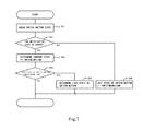
- FIG. 7 is a flowchart showing a schematic procedure of judging the operating state of the operation switch in a preferred embodiment of the present invention.
- FIG. 1 shows the internal configuration of an electrical parking brake device.
- An electrical parking brake device 1 includes at least an operation switch 10 and a control circuit 20 .
- the operation switch 10 preferably includes a switch button 15 that is operated by a driver, a plurality of miniature switches S 1 to S 5 that operate in conjunction with the state of the switch button, operation switch terminals A 1 to A 4 , and inside conductors that include conductors 11 to 14 .
- the operation switch 10 is put into one of three operating states of an On state (Apply), an Off state (Release) and a neutral state (Neutral).
- control circuit 20 includes control circuit terminals B 1 to B 4 , a switch verification circuit 40 , management circuitry (such as, for example, Parking Brake Control circuitry defined by a CPU and memory or defined by an integrated circuit or other discrete circuit components) 30 that manages the parking brake device, and brake application command circuitry (such as, for example, Parking Brake Operation Control circuitry defined by a CPU and memory or defined by an integrated circuit or other discrete circuit components) 50 , and in the present preferred embodiment, further includes an operating state display 60 .
- the switch verification circuit 40 and the management circuitry 30 electrically detects closed circuits that are provided in the interior of the operation switch 10 and that are independent in terms of two of the operation switch terminals A 1 to A 4 .
- operation circuits 41 change the electrical states of the operation switch terminals that are electrically connected with the operation circuits 41 . Then, the management circuitry 30 verifies the electrical state after the change, so that the formation state of closed circuits is confirmed. Thus, the operation switch 10 detects one of the three normal operating states and the failure state. For informing the driver of the detected operating state of the operation switch 10 , the management circuitry 30 displays the operating state on the operating state display 60 . Further, the command 501 of a brake operation corresponding to the operating state is sent to the brake application command circuitry 50 .
- the brake application command circuitry 50 after receiving the command, issues an operating command 502 to a brake (not specifically illustrated in the Drawings, but which receives the operating command 502 ) of an object vehicle.
- a brake not specifically illustrated in the Drawings, but which receives the operating command 502
- the operation of the application/release of the parking brake is actualized.
- the operation switch terminals A 1 to A 4 and the control circuit terminals B 1 to B 4 are connected by outside conductors 21 to 24 between the operation switch 10 and the control circuit 20 , and thus, the electrical states of the operation switch terminals A 1 to A 4 are transmitted to the control circuit 20 side.
- the On or Off operation of the switch button 15 is performed by the driver.
- the switch button 15 transitions to the neutral state by an internal spring mechanism or the like.
- the pushing state is sustained for a certain amount of time (hereinafter, the sustained time is referred to as the “pushing time”), for example, for at least about 0.2 seconds, while the On or Off state is kept.
- the switch button 15 transitions to the neutral state, and becomes stable in this state.
- the miniature switches S 1 to S 5 have a structure called a change-over switch. This is shown in FIG. 2 .
- the change-over switch is a switch that has three terminals a, b, c and that connects the terminal a and the terminal b at the time of the Off state and connects the terminal a and the terminal c at the time of the On state.
- the miniature switches S 1 to S 3 become the On state.
- This conjunction relation is shown by a broken line 151 in FIG. 1 .
- the miniature switches S 4 to S 5 become the On state.
- This conjunction relation is shown by a broken line 152 in FIG. 1 .
- the On state of the miniature switches transitions to the Off state, after the elapse of a certain amount of time.
- the operation switch terminals A 1 to A 4 and the miniature switches S 1 to S 5 are connected by only inside conductors in the operation switch 10 , without including diodes, resistors or the like that are other components. That is, the operation switch 10 includes a circuit in which the operation switch terminals A 1 to A 4 are connected with only the plurality of miniature switches S 1 to S 5 by the inside conductors.
- the configuration of the internal circuit of the operation switch is simplified.
- the circuit provided in the operation switch 10 is miniaturized, spots for soldering or the like are decreased, and the arrangement of conductors is simplified, resulting in the reduction of the failure rate of the operation switch 10 .
- the circuit provided in the interior of the operation switch 10 defines two closed circuits that are independent in terms of the operation switch terminals A 1 to A 4 , for each of the neutral state, the On state (Brake Apply) and the Off state (Brake Release), which are the three operating states of the operation switch 10 .
- the closed circuits will be described with reference to FIG. 3 to FIG. 5 .
- FIG. 3 shows the internal circuit when the operation switch 10 is in the neutral state.
- the miniature switches S 1 to S 5 are all in the Off state. That is, in the change-over switch shown in FIG. 2 , the terminal a and the terminal b are in the conducting state.
- two closed circuits of a first closed circuit “A 1 , S 1 , S 4 , S 2 , A 2 ” 110 and a second closed circuit “A 3 , S 3 , S 5 , A 4 ” 120 are mutually independent.
- the switch verification circuit 40 described later can detect the proper operating state of the operation switch 10 , even when one or more of the plurality of miniature switches S 1 to S 5 fail.
- FIG. 4 shows the internal circuit when the operation switch 10 is in the On state.
- the miniature switches S 1 to S 3 are all in the On state, and the miniature switches S 4 , S 5 are in the Off state.
- two closed circuits of a first closed circuit “A 1 , S 1 , S 3 , A 3 ” 111 and a second closed circuit “A 2 , S 2 , A 4 ” 121 are provided.
- FIG. 5 shows the internal circuit when the operation switch 10 is in the Off state (Release state).
- the miniature switches S 1 to S 3 are all in the Off state, and the miniature switches S 4 , S 5 are in the On state.
- two closed circuits of a first closed circuit “A 1 , S 1 , S 4 , A 4 ” 112 and a second closed circuit “A 2 , S 2 , S 5 , S 3 , A 3 ” 122 are provided.
- the operation switch is in the neutral state
- two or more miniature switches fail, if they are miniature switches included in only one of the first closed circuit 112 and the second closed circuit 122 , the other closed circuit is in the conducting state, and it is possible to detect the proper operating state of the operation switch 10 .
- the specific circuit configuration of the operation switch 10 has been shown, to facilitate understanding of the features of the present invention.
- Various preferred embodiments of the present invention is based on the internal configuration of the operation switch 10 with only the plurality of miniature switches and the conductors and the formation of two closed circuits that are independent in terms of two terminals of the operation switch terminals A 1 to A 4 . Then, even in the case of the failure of at least one miniature switch, the operating state of the operation switch is properly detected by confirming that one independent closed circuit normally operates.
- the miniature switch may be defined by a switch that includes two terminals and that performs merely the On/Off operation, instead of the change-over switch shown in FIG. 2 .
- the management circuitry 30 sends an instruction 300 to the switch verification circuit 40 , and thus, electrically confirms that at least one closed circuit that is independent in terms of two terminals of the operation switch terminals A 1 to A 4 is provided in the interior of the operation switch 10 .
- the management circuitry 30 detects which of the four operating states is the operating state of the operation switch 10 , based on the state of the closed circuit. In the following, the electrical confirmation operation will be described.
- FIG. 6 is a diagram exemplifying the internal configuration of an operation circuit that is included in the switch verification circuit.
- reference character Bn denotes one of the control circuit terminals B 1 to B 4 representatively
- reference character n denotes an integer of 1 to 4.
- the portion surrounded by the broken line shows an operation circuit 41 , and this corresponds to the operation circuit 41 in the interior of the switch verification circuit 40 in FIG. 1 .
- the operation circuit 41 is preferably defined by two constant current sources 411 , 412 and two switches SS 1 , SS 2 .
- the constant current source schematically shows a function to roughly equalize the potentials of both ends by applying a constant current.
- the potential difference between both ends of the constant current source is a value that is sufficiently negligible compared to the power source voltage.
- the function of the constant current source can be actualized in various manners by publicly known technologies. Further, the two switches are turned On/Off through inside wires 301 , 302 of the control circuit, by the instruction from the management circuitry 30 . Here, the two switches are not put into the On state simultaneously.
- the Bn terminal has a High level that is the power source potential (hereinafter, the potential is referred to as “VH”).
- the Bn terminal has a Low level that is the ground potential (hereinafter, the potential is referred to as “VL”).
- the management circuitry 30 appropriately turns On the switches SS 1 , SS 2 for each of the four operation circuits 41 , and thus, operates the potentials of the control circuit terminals B 1 to B 4 , to one of VH, VL and an unconnected state in which the control circuit terminal does not have any of these potentials (hereinafter, referred to as an “Open state”).
- an Open state an unconnected state in which the control circuit terminal does not have any of these potentials
- the switch button 15 transitions to the neutral state by an internal spring mechanism.
- the time (pushing time) during which the driver is pushing the switch button is, for example, at least about 0.2 seconds.
- the miniature switches S 1 to S 5 perform the On/Off operation.
- the management circuitry 30 continuously monitors the electrical states of the control circuit terminals B 1 to B 4 , and detects that the switch button 15 has been pushed by the driver, when the electrical states change. In the following, the operation will be described specifically.
- the operation switch 10 is in the neutral state.
- the two closed circuits 110 , 120 shown in FIG. 3 are provided in the operation switch 10 .
- the management circuitry 30 operates (B 1 , B 2 , B 3 , B 4 ) to the states of (VH, Open, Open, Open), respectively.
- the management circuitry 30 checks the electrical states of (B 2 , B 3 , B 4 ), and confirms that only B 2 has VH. Thus, it is confirmed that the closed circuit 110 is properly defined.
- the management circuitry 30 operates (B 1 , B 2 , B 3 , B 4 ) to the states of (Open, Open, VH, Open), respectively. Then, the management circuitry 30 checks the electrical states of (B 1 , B 2 , B 4 ), and confirms that only B 4 has VH. Thus, it is confirmed that the closed circuit 120 is properly defined. By repeating the above two confirmation operations, the management circuitry 30 recognizes that the operation switch 10 is in the neutral state. The operation of repeatedly confirming the neutral state is referred to as the “neutral idling operation”, hereinafter.
- the closed circuit check in the neutral idling operation detects that the switch button 15 is not in the neutral state.
- the management circuitry 30 recognizes that the switch button 15 has been pushed, and after waiting for the pushing state to become electrically stable, checks each closed circuit formation state shown in FIG. 4 and FIG. 5 , through the operation circuits 41 , in order to detect to which side the switch button 15 is has been pushed.
- the state in which the switch button 15 is pushed is sustained for the pressing time (for example, at least 0.2 seconds), and therefore, the check only needs to be completed in this time.
- the management circuitry 30 needs to monitor when the pushing time ends and the switch button 15 transitions to the neutral state.
- the monitoring operation is able to be realized by performing a repetitive operation that is similar to the neutral idling operation. That is, when the switch button 15 is in the On state (Brake Apply), the management circuitry 30 confirms that the two independent closed circuits 111 , 121 shown in FIG. 4 are continuously provided. Then, when the state changes, the pushing time is regarded to end. Thereafter, it is only necessary to confirm the closed circuits in FIG. 3 , which are the closed circuits in the neutral state. The same goes for the case where the switch button 15 is in the Off state (Brake Release).
- the operating state of the electrical parking brake device 1 is held, and a secure and safe parking brake operation is actualized.
- the failure is recovered, and the normal operation is ensured.
- the two mutually independent closed circuits shown in FIG. 3 to FIG. 5 are provided corresponding to the three normal operating states of the operation switch 10 , and in the case where one of the closed circuits is independently provided, the proper operating state is brought. Then, in the case of being in a state other than the proper state, a process of, for example, informing the driver of the failure is performed.
- the switch button 15 when the driver pushes the switch button 15 and thereafter releases it, the switch button 15 returns to the neutral state by the action of a spring or the like.
- the management circuitry 30 recognizes the failure state during the pushing time after the driver pushes the switch button 15 , although the internal state of the operation switch 10 is normal in the neutral state. This is because the judgment in the failure check of the operation switch 10 in the pushing state is performed by only the states of the two independent closed circuits in FIG. 4 or FIG. 5 that are provided in the pushing time. In the usual failure check, the detection is able to be almost completed by the first-stage check.
- the failure state is recognized, as a second-stage check step, the closed circuit state is checked also in the neutral state, which surely occurs before or after the failure state, and the verification is performed along with the current closed circuit state that is the failure state.
- the failure is, for example, which of the Off-state disconnection failure, the On-state disconnection failure, an Off-state conduction failure, an On-state conduction failure and the like the failure is.
- the Off-state conduction failure is a “failure in the Off state by which the terminal a and the terminal b are always in the conducting state” in FIG.
- the On-state conduction failure is a “failure in the On state by which the terminal a and the terminal c are always in the conducting state” in FIG. 2 .
- FIG. 7 shows a schematic procedure in which the management circuitry 30 determines the operating state of the switch button 15 .
- the procedure of FIG. 7 is preferably repeatedly executed with a constant period of about 10 milliseconds, for example.
- step S 01 the switch button state is checked.
- step S 02 the switch button state is determined, and in the case where it can be determined that the switch button state is one of the three states of the neutral state, the On state and the Off state, the procedure proceeds to step S 03 . If it cannot be determined that the switch button is in one of the three states in step S 02 , the procedure proceeds to step S 06 , and the information that the state of the switch button cannot be determined is stored. The specific example will be described later.
- step S 03 it is determined which of the neutral state, the On state and the Off state the switch button state is. Subsequently, in step S 04 , it is determined whether the switch button state before this switching of the switch button is the failure state, and in the case of the failure state, the procedure proceeds to step S 05 . Then, in step S 05 , the last state of the switch button is determined by using the current state of the switch button.
- the switch button is in the neutral state in FIG. 3
- the miniature switches S 1 to S 5 are all in the Off state. Therefore, in the neutral state, the Off-state conduction failure of the miniature switches S 1 to S 5 cannot be detected.
- the switch button is in the On state in FIG. 4
- the Off-state conduction failure of the miniature switches S 1 to S 3 can be detected.
- the switch button is in the Off state in FIG. 5
- the Off-state conduction failure of the miniature switches S 4 to S 5 can be detected.
- the two proper closed circuits are not defined even when the switch button is turned On.
- the circuit “A 2 , S 2 , A 4 ” is defined.
- the circuit “A 1 , S 1 , S 3 , A 3 ” is not defined, and instead, a circuit “A 3 , S 3 , S 5 , A 4 ” is defined.
- These two circuits are circuits that commonly have the operation switch terminal A 4 .
- the one circuit “A 2 , S 2 , A 4 ” is a circuit in which the switch button is recognized to be in the On state
- the other circuit “A 3 , S 3 , S 5 , A 4 ” is a circuit in which the switch button is recognized to be in the neutral state. Therefore, in this state, it cannot be determined whether the switch button is in the On state or in the neutral state.
- the management circuitry 30 stores this failure state. After that, the switch button surely becomes the neutral state.
- the two proper closed circuits of “A 1 , S 1 , S 4 , S 2 , A 2 ” 110 and “A 3 , S 3 , S 5 , A 4 ” 120 are recognized. Since the switch button is in the neutral state at this time, it is able to be determined that the previously stored state is not the neutral state but the On state.
- the two proper closed circuits are not defined even when the switch button is in the neutral state.
- the circuit “A 3 , S 3 , S 5 , A 4 ” is defined.
- the circuit “A 1 , S 1 , S 4 , S 2 , A 2 ” is not defined, and instead, a circuit “A 2 , S 2 , A 4 ” is defined.
- These two circuits are circuits that commonly have the operation switch terminal A 4 .
- the one circuit “A 3 , S 3 , S 5 , A 4 ” is a circuit in which the switch button is recognized to be in the neutral state
- the other circuit “A 2 , S 2 , A 4 ” is a circuit in which the switch button is recognized to be in the On state. Therefore, in this state, it cannot be determined whether the switch button is in the neutral state or in the On state.
- the management circuitry 30 stores this failure state. After that, when the switch button becomes the On state, the two proper closed circuits of “A 1 , S 1 , S 3 , A 3 ” 111 and “A 2 , S 2 , A 4 ” 121 are recognized. Since the switch button is in the On state at this time, it is able to be determined that the previously stored state is not the On state but the neutral state.
- the electrical parking brake device according to preferred embodiments of the present invention, it is possible to provide a small and low-cost electrical parking brake device that reduces the failure rate of the operation switch to be operated by the driver of the vehicle.
- the electrical parking brake device according to preferred embodiments of the present invention is suitably used in vehicles including four-wheeled vehicles, for example.
Landscapes
- Engineering & Computer Science (AREA)
- General Engineering & Computer Science (AREA)
- Mechanical Engineering (AREA)
- Transportation (AREA)
- Valves And Accessory Devices For Braking Systems (AREA)
- Arrangement Or Mounting Of Control Devices For Change-Speed Gearing (AREA)
- Keying Circuit Devices (AREA)
Abstract
Description
Claims (10)
Applications Claiming Priority (6)
| Application Number | Priority Date | Filing Date | Title |
|---|---|---|---|
| JP2015170979 | 2015-08-31 | ||
| JP2015-170979 | 2015-08-31 | ||
| JP2016-127191 | 2016-06-28 | ||
| JP2016127191 | 2016-06-28 | ||
| JP2016166868A JP2018002129A (en) | 2015-08-31 | 2016-08-29 | Electric parking brake device |
| JP2016-166868 | 2016-08-29 |
Publications (2)
| Publication Number | Publication Date |
|---|---|
| US20170059040A1 US20170059040A1 (en) | 2017-03-02 |
| US10293766B2 true US10293766B2 (en) | 2019-05-21 |
Family
ID=58097756
Family Applications (1)
| Application Number | Title | Priority Date | Filing Date |
|---|---|---|---|
| US15/251,004 Expired - Fee Related US10293766B2 (en) | 2015-08-31 | 2016-08-30 | Electrical parking brake device |
Country Status (2)
| Country | Link |
|---|---|
| US (1) | US10293766B2 (en) |
| CN (1) | CN106476779A (en) |
Families Citing this family (3)
| Publication number | Priority date | Publication date | Assignee | Title |
|---|---|---|---|---|
| US20180144560A1 (en) * | 2016-11-22 | 2018-05-24 | GM Global Technology Operations LLC | Motor vehicle device and system controller and method |
| DE102018220583A1 (en) * | 2018-11-29 | 2020-06-04 | Robert Bosch Gmbh | Checking unit for an actuating device of an electrical device |
| CN118790212A (en) * | 2024-07-24 | 2024-10-18 | 东风华神汽车有限公司 | Electronic handbrake control system and method |
Citations (8)
| Publication number | Priority date | Publication date | Assignee | Title |
|---|---|---|---|---|
| US20040113489A1 (en) * | 2002-10-22 | 2004-06-17 | Honda Motor Co., Ltd. | Electric parking brake system |
| EP1447830A1 (en) * | 2003-02-13 | 2004-08-18 | Ford Global Technologies, Inc., A subsidiary of Ford Motor Company | Switching device for coding of different states |
| US20090090610A1 (en) * | 2005-12-20 | 2009-04-09 | Matthias Grimm | Pushbutton for Actuating an Electropneumatic Parking Brake (Eph) |
| JP2010512277A (en) | 2006-12-11 | 2010-04-22 | ルノー・エス・アー・エス | Electronically controlled parking brake system |
| US8432060B2 (en) | 2007-11-26 | 2013-04-30 | Lucas Automotive Gmbh | Device for the electric actuation of a safety-critical system |
| JP2014104880A (en) | 2012-11-28 | 2014-06-09 | Advics Co Ltd | Electrically-driven brake control device |
| US20160268075A1 (en) * | 2013-10-22 | 2016-09-15 | Kabushiki Kaisha Tokai Rika Denki Seisakusho | Switch device |
| JP2017024507A (en) * | 2015-07-21 | 2017-02-02 | 日立オートモティブシステムズ株式会社 | Electric parking brake device |
-
2016
- 2016-08-30 US US15/251,004 patent/US10293766B2/en not_active Expired - Fee Related
- 2016-08-31 CN CN201610793430.2A patent/CN106476779A/en active Pending
Patent Citations (8)
| Publication number | Priority date | Publication date | Assignee | Title |
|---|---|---|---|---|
| US20040113489A1 (en) * | 2002-10-22 | 2004-06-17 | Honda Motor Co., Ltd. | Electric parking brake system |
| EP1447830A1 (en) * | 2003-02-13 | 2004-08-18 | Ford Global Technologies, Inc., A subsidiary of Ford Motor Company | Switching device for coding of different states |
| US20090090610A1 (en) * | 2005-12-20 | 2009-04-09 | Matthias Grimm | Pushbutton for Actuating an Electropneumatic Parking Brake (Eph) |
| JP2010512277A (en) | 2006-12-11 | 2010-04-22 | ルノー・エス・アー・エス | Electronically controlled parking brake system |
| US8432060B2 (en) | 2007-11-26 | 2013-04-30 | Lucas Automotive Gmbh | Device for the electric actuation of a safety-critical system |
| JP2014104880A (en) | 2012-11-28 | 2014-06-09 | Advics Co Ltd | Electrically-driven brake control device |
| US20160268075A1 (en) * | 2013-10-22 | 2016-09-15 | Kabushiki Kaisha Tokai Rika Denki Seisakusho | Switch device |
| JP2017024507A (en) * | 2015-07-21 | 2017-02-02 | 日立オートモティブシステムズ株式会社 | Electric parking brake device |
Also Published As
| Publication number | Publication date |
|---|---|
| CN106476779A (en) | 2017-03-08 |
| US20170059040A1 (en) | 2017-03-02 |
Similar Documents
| Publication | Publication Date | Title |
|---|---|---|
| US10293766B2 (en) | Electrical parking brake device | |
| US20200062200A1 (en) | Power Distributor, and On-Board Electrical System Having at Least One Power Distributor | |
| KR102061259B1 (en) | Arrangement and method for updating a control software in a high-voltage control unit | |
| CN113748582A (en) | Method and device for supplying energy to a load of a vehicle | |
| US10787135B2 (en) | Switching circuit, failure detection method therefor, and control apparatus | |
| JP5546524B2 (en) | Vehicle starter motor drive circuit | |
| KR102690454B1 (en) | Redundancy system of vehicle and, apparatus and method for supplying power thereof | |
| JP5182581B2 (en) | Electrical junction box and distribution unit | |
| JP5730639B2 (en) | Electronic control device for vehicle and electronic control system for vehicle | |
| KR102079484B1 (en) | Intelligent switch for automotive application | |
| CN111186484B (en) | Sensor information output apparatus and vehicle control apparatus | |
| KR101862086B1 (en) | Master controller | |
| CN107791252B (en) | Control device, control system, control method, and recording medium | |
| US11242065B2 (en) | Device and method for controlling a signal connection of a vehicle | |
| KR102029371B1 (en) | Power Supply system and method for ethernet communication network in vehicle | |
| KR20220032362A (en) | Power control apparatus in autonomous vehicle and method for monitering power status thereof | |
| JP2008519724A (en) | Method and apparatus for locking a steering column | |
| JP2018002129A (en) | Electric parking brake device | |
| US20090230765A1 (en) | System and method for delivering power to an electric motor of an automotive vehicle | |
| CN110171392B (en) | Wiper drive circuit | |
| JP7322742B2 (en) | Fail-safe controller | |
| WO2021148495A1 (en) | Electronic computing device for a motor vehicle with a circuit, which is supplied with a voltage via a control device external to computing device, arrangement as well as method | |
| EP4491467B1 (en) | Control system configured for controlling steering and braking of a vehicle | |
| JP4593135B2 (en) | Computer system, peripheral device, and peripheral device testing method | |
| JP2018124632A (en) | Electronic control device |
Legal Events
| Date | Code | Title | Description |
|---|---|---|---|
| AS | Assignment |
Owner name: NIDEC ELESYS CORPORATION, JAPAN Free format text: ASSIGNMENT OF ASSIGNORS INTEREST;ASSIGNOR:WATANABE, YUTAKA;REEL/FRAME:039573/0430 Effective date: 20160822 |
|
| STPP | Information on status: patent application and granting procedure in general |
Free format text: NOTICE OF ALLOWANCE MAILED -- APPLICATION RECEIVED IN OFFICE OF PUBLICATIONS |
|
| STPP | Information on status: patent application and granting procedure in general |
Free format text: PUBLICATIONS -- ISSUE FEE PAYMENT VERIFIED |
|
| STCF | Information on status: patent grant |
Free format text: PATENTED CASE |
|
| FEPP | Fee payment procedure |
Free format text: MAINTENANCE FEE REMINDER MAILED (ORIGINAL EVENT CODE: REM.); ENTITY STATUS OF PATENT OWNER: LARGE ENTITY |
|
| LAPS | Lapse for failure to pay maintenance fees |
Free format text: PATENT EXPIRED FOR FAILURE TO PAY MAINTENANCE FEES (ORIGINAL EVENT CODE: EXP.); ENTITY STATUS OF PATENT OWNER: LARGE ENTITY |
|
| STCH | Information on status: patent discontinuation |
Free format text: PATENT EXPIRED DUE TO NONPAYMENT OF MAINTENANCE FEES UNDER 37 CFR 1.362 |
|
| FP | Lapsed due to failure to pay maintenance fee |
Effective date: 20230521 |