US1029128A - Heilmann comber. - Google Patents
Heilmann comber. Download PDFInfo
- Publication number
- US1029128A US1029128A US61111811A US1911611118A US1029128A US 1029128 A US1029128 A US 1029128A US 61111811 A US61111811 A US 61111811A US 1911611118 A US1911611118 A US 1911611118A US 1029128 A US1029128 A US 1029128A
- Authority
- US
- United States
- Prior art keywords
- piecing
- comber
- horse
- combing
- standards
- Prior art date
- Legal status (The legal status is an assumption and is not a legal conclusion. Google has not performed a legal analysis and makes no representation as to the accuracy of the status listed.)
- Expired - Lifetime
Links
- 241000347389 Serranus cabrilla Species 0.000 title description 27
- 241000195955 Equisetum hyemale Species 0.000 description 25
- 241000758993 Equisetidae Species 0.000 description 3
- 241001125879 Gobio Species 0.000 description 3
- 239000010985 leather Substances 0.000 description 2
- 229910001369 Brass Inorganic materials 0.000 description 1
- 239000010951 brass Substances 0.000 description 1
- 238000004140 cleaning Methods 0.000 description 1
- 238000006073 displacement reaction Methods 0.000 description 1
- 230000002000 scavenging effect Effects 0.000 description 1
Images



Classifications
-
- D—TEXTILES; PAPER
- D01—NATURAL OR MAN-MADE THREADS OR FIBRES; SPINNING
- D01G—PRELIMINARY TREATMENT OF FIBRES, e.g. FOR SPINNING
- D01G19/00—Combing machines
- D01G19/06—Details
- D01G19/14—Drawing-off and delivery apparatus
Definitions
- the horse-tails which support the upper piecing-roll and clearer, and the sliver pan, and the top of the front inclosing casing have all been supported by a longitudinal rod or shaft mounted close to and parallel with the lower piecing roll and. between that roll and the back of the sliver pan.
- Such a rod extends the length of the machine, being common to all the combing heads thereof, and the proximity of it and its attached parts, to the piecing rolls, produces therewith a complicated assemblage of supporting and operating mechanism, from which it is most diflicult to clean the dirt and surplus oil that collects and is apt to accumulate thereon, so as to prevent its working onto the faces of the rolls and soiling the prod not; and by reason of the necessary compactness of these parts when so supported, it has been most difficult to manipulate the individual members of piecing mechanism.
- My invention seeks to avoid or reduce these principal objections in existing machines, and consists, briefly, in' the application of suitable means to the intermediate frame standards thereof for performing the same supporting functions that the rod referred to has hitherto performed, but which may be arranged in planes close to the frame standards and sufficiently remote from the piecing-rolls to be easily cleansed and thereby avoidthe danger of contaminating the sliver.
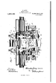
- Figure 1 is a vertical transverse section through one of the combmg heads of a Heilmann comber embodying the improvements of this invention, the section being taken centrally through the middle of thecombing head, as will be apparent;
- Fig. 2 is a top plan in enlarged scale of parts of the piecing mechanism adjacent to one of the intermediate frame standards, the sliver pan being removed;
- Fig. 3 is a vertical section at right angles to the piec- 1ng-rolls,showing the same partsthat appear in Fig. 2 but on a slightly smaller scale;
- Fig. 4 is an elevation of the parts shown in Fig. 8 and on the same scale;
- Figs. 5, 6, 7 and 8 are perspective detailsof the pillow, horse-tail base, pillow-cap, and sliver pan seats respectively as described below.
- the comber frame comprises a main horizontal girder 1 (Fig. 1) extending the length of the machine and upon which the series of upright frame standards referred to above are mounted.
- Fig. 1 main horizontal girder 1
- the standards 2 may be made of any usual or suitable shape to support the lap-feeding dievices, the nipper frame, the combing mechanism and other usual parts, so that they will operate according to the well known Heilmann principle which also need not be here described.
- the piecing mechanism comprises a lower piecing roll 7, an upper piecing or detaching roll 8, usually leather covered, and an upper fluted piecing-roll 9, usually of brass.
- the lower roll is formed on a longitudinal shaft common while the two upper rolls are individual to each combing-head, and are driven in Whole or in part by their contact with the lower roll.
- each block comprising a base member or pillow 11, such as shown by Fig. 5, and a cap piece 12, such as shown by Fig. 7.
- The'pillow is provided with an oblong slot 13 to receive a bolt 14 by means of which it is adjustable on the top of the standard in a direction toward and from the combing cylinder 6, and its journal seat 15 for the lower piecingroll shaft is located at'the rear end of the block, as shown clearly in Fig. 5.
- the cap piece 12 is adapted to be held in place on the pillow and over the-bearing surface, by means of a suitable mortise-joint and a bolt 16.
- all of the remaining parts which constitute the piecing mechanism, including the sliver pan are directly carried by the pillow 11, upon seats thereon which occupy different positions in vertical planes adjacent to the upright frame standards as distinguished from prior means of support, wherein some or all of the said parts are carried on a single horizontal member or rod spanning the combing head space.
- the pillow is provided with one or more lateral projections in the nature of bracket arms extending inwardly from the frame standard a sufficient distance to enable them to provide the bearings or seats for the parts they support, without encroaching on the space required for the sliver pan and so as to leave a substantially clear open space immediately below the working portions of the piecing-rolls.
- the pillows intended for use on the end frame standards are of course provided with the lateral arms on one side only, as will be readily understood, but for the intermediate standards they have such lateral projections extending therefrom 011 both sides as in the case illustrated in Fig. 5. Beginning at the rearmost end, the first pair of bracket arms marked 17 spring from below the journal surface 15 and extend rearwardly and upwardly therefrom to hold the bearing blocks 18 (Fig.
- the upper, fluted piecing roll 9 is held by its end gudgeons in the horse-tail at each side so that it will nor mally restupon the top of the lower roll, but so that it can be removed therefrom by swinging the horse-tail upward in the usual manner.
- a clearer cover 9 is also carried in slots in the horse-tail as shown in Fig. 1.
- the horse-tail base 22 includes a spring plunger 24 acting on the horse-tail to maintain the roller 9 either in pressing engagement with the lower roll or in its uplifted position, but the particular means of mounting the upper roll or the horse-tail upon the lateral arm 21 and thus upon the pillow, is not a matter of consequence to the present invention so long as the supporting arm or horse-tail base springs from a point in front of the pivot of the horse-tail or the stirrup.
- the horse-tail base is provided with an oblong slot for its holding bolt 25 whereby it can be adjusted forward and back with respect to the pillow arm and the other seats formed on the pillow.
- the same pillow arm 21 is extended beyond the seat for the horse-tail base in the form of a lug or ear 26 which projects into the combing-head space below the said seat and carries a rearwardly and downwardly inclined hook-.
- This shelf27 (Fig. 8) forming a seat for the sliver pan 3 as indicated in Fig. 1.
- This shelf27 is provided with a bolt hole considerably larger than the bolt by which it is secured in place, as shown more clearly.
- Each of the pillow arms 21 is further provided with a rearwardly and downwardly extending branch arm 28 terminating in a lateral and inwardly projecting horn .29, which occupies a position close to the frame standard but considerably below the horse-tail and the piecing rolls, so as to leave a clear wiping space therebetween.
- the front section 30'of the casing which incloses the forward side of the combing cylinder and its scavenging mechanism is adapted to be en gaged and supported against displacement by these horns at the opposite sides of the combing head space and for this purpose the section of the casing is provided with clips, as shown at 31, tlClttlitQCl to be seated thereon.
- the supporting seats for the horsetail, pan and easing are preferably all formed on the single pillow arm 21, as above shown, it will be observed that separate arms can be provided for each seat, if desired, and such arms may be integral with or attached to the pillow as preferred and moreover it will be obvious that the pillow itself may be in one or more parts if preferred, that is to say, the part which forms the ournal seat 15 may be divided or separate from the front portion, provided both are appropriately secured to the frame standard. In any case it will be observed that by the removal of the sliver-pan and the sliver guard (33, Fig.
- the upright frame standards forming the combing-head space between them and provided with adjustable plumber blocks having bracket arms thereon terminating in said space, in combination with a rearwardly extending horsetail base on one of the arms, a horse-tail carried thereby and a piecing roller in the horse-tail.
- the upright standards forming a combing-head space between them, pillows adjustably mounted thereon and provided with members projecting laterally therefrom and terminating in the said combing-head space, in combination with horse-tail bases and a sliver-pan carried by said members.
- the framestandards forming a combing-head space between them, pillows adjustably mounted on the standards and formed with lateral integral arms, in combination with a sliver pan in the said combing space supported on said arms.
- a pillow adjustably mounted on an upright frame standard of the comber and formed with a laterally projecting means, integral therewith, providing supports for the sliver-pan, the front shield and the horse-tails.
- a pillow adjustably mounted on an upright frame standard and formed with an integral laterally projectingarm, a horse-tail base secured to said arm and extending rearwardly therefrom, and a sliver-pan seat also formed on said arm.
- a pillow mounted on an intermediate frame-standard of the comber and formed with lateral arms on both sides thereof, a lower piecing-roll shaft journaled in the pillow, and rearwardly extending horse-tail bases carried b the arms thereof.
- a pillow mounted on an intermediate frame-standard of the comber, and provided with later ally projecting arms on both sides thereof,
- each of said arms being provided with means to support a horse-tail base, a sliver-pan and a front shield.
Landscapes
- Engineering & Computer Science (AREA)
- Textile Engineering (AREA)
- Preliminary Treatment Of Fibers (AREA)
Description
H. JARRY.
HEILMANN OOMBEE.
APPLICATION FILED TEEN, 1911.
Patented June 11, 1912.-
4 SHEETS-SHEET 1.
H. JARRY.
HEILMANN GOMBER.
APPLICATION TILED IEB.2'1,1911.-
1,029,128, Patented June 11, 1912.
4 SHEETSSHBET 3.
Y n m ww h Maw W612 Q W 33%;; Grumman COLUMBIA PLANUGRAPII c0 WASHINGTON. D. c.
TTE STATES PATENT OFFICE.
I-IORMIDAS JARBY, OF LAWRENCE, MASSACHUSETTS, iASSIGNOR TO THE WHITIN MACHINE WORKS, OF WHITINSVILLE, MASSAGHU$ETT A CORPORATION OF MASSACHUSETTS.
Specification of Letters Patent.
HEILMANN COMBER.
Patented June 11, 191 2.
Application filed February 27,1911. Serial No- 611,118.
insuring better and cleaner results in the operation of the machine and improving the facilities for wiping the detaching and piecing mechanism and the adjacent parts.
As heretofore and generally constructed, the horse-tails which support the upper piecing-roll and clearer, and the sliver pan, and the top of the front inclosing casing have all been supported by a longitudinal rod or shaft mounted close to and parallel with the lower piecing roll and. between that roll and the back of the sliver pan. Such a rod extends the length of the machine, being common to all the combing heads thereof, and the proximity of it and its attached parts, to the piecing rolls, produces therewith a complicated assemblage of supporting and operating mechanism, from which it is most diflicult to clean the dirt and surplus oil that collects and is apt to accumulate thereon, so as to prevent its working onto the faces of the rolls and soiling the prod not; and by reason of the necessary compactness of these parts when so supported, it has been most difficult to manipulate the individual members of piecing mechanism.
My invention seeks to avoid or reduce these principal objections in existing machines, and consists, briefly, in' the application of suitable means to the intermediate frame standards thereof for performing the same supporting functions that the rod referred to has hitherto performed, but which may be arranged in planes close to the frame standards and sufficiently remote from the piecing-rolls to be easily cleansed and thereby avoidthe danger of contaminating the sliver. These new Supporting means will be more readily understood by reference to the accompanying four sheets of drawings which form part of this specification.
In these drawings, Figure 1 is a vertical transverse section through one of the combmg heads of a Heilmann comber embodying the improvements of this invention, the section being taken centrally through the middle of thecombing head, as will be apparent; Fig. 2 is a top plan in enlarged scale of parts of the piecing mechanism adjacent to one of the intermediate frame standards, the sliver pan being removed; Fig. 3 is a vertical section at right angles to the piec- 1ng-rolls,showing the same partsthat appear in Fig. 2 but on a slightly smaller scale; Fig. 4 is an elevation of the parts shown in Fig. 8 and on the same scale; Figs. 5, 6, 7 and 8 are perspective detailsof the pillow, horse-tail base, pillow-cap, and sliver pan seats respectively as described below.
It will be understood by those familiar with the subject that the comber frame comprises a main horizontal girder 1 (Fig. 1) extending the length of the machine and upon which the series of upright frame standards referred to above are mounted. These standards form the end and intermediate supports of the several combing heads of the comber, but one only of them is shown in the drawings, being marked 2, because they are all alike and a description of the new supporting means with relation 'to one of them will obviously suffice for the whole machine. The standards 2 may be made of any usual or suitable shape to support the lap-feeding dievices, the nipper frame, the combing mechanism and other usual parts, so that they will operate according to the well known Heilmann principle which also need not be here described. These parts appear in their usual arrangement in Fig. 1, and it will be understood that they operate to comb the staple in successive tufts or detachments, which are successively introduced in an overlapping arrangement into the piecing mechanism and by it formed into a continuous sliver which passes thence into the sliver pan 3, through its condensing trumpet, and the calendar rolls 4 to the apron 5. The piecing mechanism comprises a lower piecing roll 7, an upper piecing or detaching roll 8, usually leather covered, and an upper fluted piecing-roll 9, usually of brass. The lower roll is formed on a longitudinal shaft common while the two upper rolls are individual to each combing-head, and are driven in Whole or in part by their contact with the lower roll. By reason of the form of their support the rolls-8 and 9 are normally removable, while the other roll is normally fixed. Themounting of the shaft of the lower piecing roll is provided by a set of plumberblocks mounted on the inclined top margins of the several frame standards 2, each block comprising a base member or pillow 11, such as shown by Fig. 5, and a cap piece 12, such as shown by Fig. 7. The'pillow is provided with an oblong slot 13 to receive a bolt 14 by means of which it is adjustable on the top of the standard in a direction toward and from the combing cylinder 6, and its journal seat 15 for the lower piecingroll shaft is located at'the rear end of the block, as shown clearly in Fig. 5. The cap piece 12 is adapted to be held in place on the pillow and over the-bearing surface, by means of a suitable mortise-joint and a bolt 16. According to this'invention in its preferred form, all of the remaining parts which constitute the piecing mechanism, including the sliver pan, are directly carried by the pillow 11, upon seats thereon which occupy different positions in vertical planes adjacent to the upright frame standards as distinguished from prior means of support, wherein some or all of the said parts are carried on a single horizontal member or rod spanning the combing head space. For this purpose the pillow is provided with one or more lateral projections in the nature of bracket arms extending inwardly from the frame standard a sufficient distance to enable them to provide the bearings or seats for the parts they support, without encroaching on the space required for the sliver pan and so as to leave a substantially clear open space immediately below the working portions of the piecing-rolls. The pillows intended for use on the end frame standards are of course provided with the lateral arms on one side only, as will be readily understood, but for the intermediate standards they have such lateral projections extending therefrom 011 both sides as in the case illustrated in Fig. 5. Beginning at the rearmost end, the first pair of bracket arms marked 17 spring from below the journal surface 15 and extend rearwardly and upwardly therefrom to hold the bearing blocks 18 (Fig. 3) upon which the sleeved gudgeons 8 of the leather piecing roll 8 are adapted to rest. The bearing blocks are inclined, as shown, and a pair of stirrups 19 applied one upon the gudgeon at each end of the roll, presses it clown- .wardly so that its body portion is pressed against the lower piecing roll 7 The stirrups extend upwardly from their respective gudgeonsand thence downwardly passing space, slightly more than bracket arms 17 V and substantially at right angles to the plane of the frame standard. On the top of each of these arms there is secured a horse-tail base 22 which is specially formed to extend rearwardly therefrom toward the piecingrolls, to form a suitable support for the horse-tail 23 which is. pivoted at the rear most part thereof. The upper, fluted piecing roll 9 is held by its end gudgeons in the horse-tail at each side so that it will nor mally restupon the top of the lower roll, but so that it can be removed therefrom by swinging the horse-tail upward in the usual manner. A clearer cover 9 is also carried in slots in the horse-tail as shown in Fig. 1. The horse-tail base 22 includes a spring plunger 24 acting on the horse-tail to maintain the roller 9 either in pressing engagement with the lower roll or in its uplifted position, but the particular means of mounting the upper roll or the horse-tail upon the lateral arm 21 and thus upon the pillow, is not a matter of consequence to the present invention so long as the supporting arm or horse-tail base springs from a point in front of the pivot of the horse-tail or the stirrup.
In the present instance and as shown at.
Fig. 6, the horse-tail base is provided with an oblong slot for its holding bolt 25 whereby it can be adjusted forward and back with respect to the pillow arm and the other seats formed on the pillow. The same pillow arm 21 is extended beyond the seat for the horse-tail base in the form of a lug or ear 26 which projects into the combing-head space below the said seat and carries a rearwardly and downwardly inclined hook-.
shaped shelf 27 (Fig. 8) forming a seat for the sliver pan 3 as indicated in Fig. 1. This shelf27 is provided with a bolt hole considerably larger than the bolt by which it is secured in place, as shown more clearly.
in Fig. 2, and is therefore capable of adjustment on the pillow-arm. mentis useful in connection with the setting of the electric stop motion mechanism of which the sliver-pan ordinarily forms a part. The forward end of the sliver pan in the case shown, rests as usual on an adjustable set screw 10 carried on a cross rod spanning theframe standards while the lateral marginsof the pan atits rear end Such adj ustrest upon the seats 27 which it will be observed are also in front of the stirrups on each side of the combing head space. Adjustment of the pan toward and from the piecing rolls is accomplished by the elongated bolt slot formed in the pun seat and by which it is bolted to the lug 26. Each of the pillow arms 21 is further provided with a rearwardly and downwardly extending branch arm 28 terminating in a lateral and inwardly projecting horn .29, which occupies a position close to the frame standard but considerably below the horse-tail and the piecing rolls, so as to leave a clear wiping space therebetween. The front section 30'of the casing which incloses the forward side of the combing cylinder and its scavenging mechanism is adapted to be en gaged and supported against displacement by these horns at the opposite sides of the combing head space and for this purpose the section of the casing is provided with clips, as shown at 31, tlClttlitQCl to be seated thereon.
IVhile the supporting seats for the horsetail, pan and easing are preferably all formed on the single pillow arm 21, as above shown, it will be observed that separate arms can be provided for each seat, if desired, and such arms may be integral with or attached to the pillow as preferred and moreover it will be obvious that the pillow itself may be in one or more parts if preferred, that is to say, the part which forms the ournal seat 15 may be divided or separate from the front portion, provided both are appropriately secured to the frame standard. In any case it will be observed that by the removal of the sliver-pan and the sliver guard (33, Fig. 1) and by turning back the horse-tails, the region under and about the lower piecing roll from end to end thereof will be rendered accessible for cleaning, and by the further removal of the front casing 30 the entire under surface of the piecing-roll is rendered accessible, and further when the parts are in working position there is no mechanism adjacent to the piecing rolls upon which lint and dirt can accumulate to such extent as to contaminate the product.
I claim:
1. In a IIeilmann comber, the combination with the upright frame-standards forming a combing-head space between them and provided with lateral projections terminating in the said space, of the removable piecing-rolls and the sliver pan supported on said projections.
2. In a Heilmann comber, the combination with the upright frame-standards forming a combing-head space between them and provided with lateral projectionsterminating in said space, of the removable piecingrolls, sliver pan and front shield all sup ported in their operative relations upon the said projections.
3. In a Heilmann comber, the combination with the removable piecingrolls and the stirrups for one of them, of the upright frame-standards provided with means projecting laterally therefrom in front of the stirrups and forming the support for the other of said rolls.
4. In a I'Ieilmann comber, the combination with the piecii'lg-rells, and the stirrups for one of them, of the framestandards forming a combing-head space between them and having lateral projections in front of the said stirrups terminating in the cmnbing-head space, and journal supports for the other piecing-roll carried by said projections and extending rearwardly therefrom.
5. In a IIeilmann comber, the combination with piecing-rolls and the stirrups for one of them, of the frame-standards forming a combing-head space bet-ween them and each provided with two bracket arms which extend laterally from the same side of the standard and provide a space between them for the stirrup, one of said arms forming the support for the stirrup-engaged piecing-roll and the other for the other.
6. In a Heilmann comber, the combination with the piecing-rolls and the stirrup for one of them, of the frame-standards forming a combing head space between them, each having two laterally projecting arms terminating in the said space on the same side thereof and providing an opening between them for the stirrup, one of said arms forming the support for the stirrup-engaged piecing-roll and a rearwardly extending horse-tail base carried by the other arm to support the other piecing roll.
7. In a IIeilmann comber, the combination of the lower piecing roll and the removable piecing rolls, the frame standards forming a combing-head space between them, lateral projections on the standards terminating in the combing head space and forming the supports for removable piecing-rolls and a sliver-pan also supported on the said projections.
S. In a Heilmann comber, the frame standards forming the combing-head space between them, in combination with a normally stationary plumber block on the standard provided with lateral projections terminating in the said space, a lower piecing-roll shaft journaled in said block, and upper piecing-rolls mounted on the projections thereon.
9. In a Heilmann comber, the upright frame standards forming the combing-head space between them and provided with adjustable plumber blocks having bracket arms thereon terminating in said space, in combination with a rearwardly extending horsetail base on one of the arms, a horse-tail carried thereby and a piecing roller in the horse-tail.
10. In a Heilmann comber, the upright standards forming a combing-head space between them, pillows adjustably mounted thereon and provided with members projecting laterally therefrom and terminating in the said combing-head space, in combination with horse-tail bases and a sliver-pan carried by said members.
11. In a Heilmann comber, the framestandards forming a combing-head space between them, pillows adjustably mounted on the standards and formed with lateral integral arms, in combination with a sliver pan in the said combing space supported on said arms.
12. In a Heilmann comber, a pillow adjustably mounted on an upright frame standard of the comber and formed with a laterally projecting means, integral therewith, providing supports for the sliver-pan, the front shield and the horse-tails.
13. In a l-Ieilmann comber, a pillow adjustably mounted on an upright frame standard and formed with an integral laterally projectingarm, a horse-tail base secured to said arm and extending rearwardly therefrom, and a sliver-pan seat also formed on said arm.
14:. In a Heilmann comber, a pillow mounted on an intermediate frame-standard of the comber and formed with lateral arms on both sides thereof, a lower piecing-roll shaft journaled in the pillow, and rearwardly extending horse-tail bases carried b the arms thereof.
15. In a I-Ieilmann comber, a pillow mounted on an intermediate frame-standard of the comber, and provided with later ally projecting arms on both sides thereof,
each of said arms being provided with means to support a horse-tail base, a sliver-pan and a front shield.
16. In a Heilmann comber, the combination with the frame standards forming a combing-head space between them, a sliverpan in said space, adjustable seats for the pan, and supporting means for said seats extending laterally from said standards.
17. In a Heilmann comber, the combination of the upright frame-standards forming a combing-head space between them, a sliver-pan in said space, pillows on the standards and sliver-pan seats adjustably secured to said pillows.
18. In a Heilmann comber the combination of the upright frame standards forming the combing-head space between them, of a pivotally mounted horse-tail, a horse-tail base supporting the pivot thereof and eX- tending forwardly from the pivot to a pointin front of same and means for adjustably connecting the forwardly extending end of said base to the frame standard whereby the said base is maintained in a fixed position.
19. In a I-Ieilmann comber, the combination with the frame standards and the lower piecing-roll shaft, of plumber blocks for said shaft mounted on the standards and having cap-pieces covering the journals of said shaft, and supporting arms on said plumber blocks projecting from points in front of the cap-pieces.
In testimony whereof, I have signed this specification in the presence of two witnesses.
HORMIDAS J ABBY.
\Vitnesses:
OSCAR L. OWEN, I WALTER T. RooHnFoRT.
Copies of this patent may be obtained for five cents each, by addressing the Commissioner of Patents,
Washington, D. G.
Priority Applications (1)
| Application Number | Priority Date | Filing Date | Title |
|---|---|---|---|
| US61111811A US1029128A (en) | 1911-02-27 | 1911-02-27 | Heilmann comber. |
Applications Claiming Priority (1)
| Application Number | Priority Date | Filing Date | Title |
|---|---|---|---|
| US61111811A US1029128A (en) | 1911-02-27 | 1911-02-27 | Heilmann comber. |
Publications (1)
| Publication Number | Publication Date |
|---|---|
| US1029128A true US1029128A (en) | 1912-06-11 |
Family
ID=3097421
Family Applications (1)
| Application Number | Title | Priority Date | Filing Date |
|---|---|---|---|
| US61111811A Expired - Lifetime US1029128A (en) | 1911-02-27 | 1911-02-27 | Heilmann comber. |
Country Status (1)
| Country | Link |
|---|---|
| US (1) | US1029128A (en) |
-
1911
- 1911-02-27 US US61111811A patent/US1029128A/en not_active Expired - Lifetime
Similar Documents
| Publication | Publication Date | Title |
|---|---|---|
| US1446750A (en) | Combing machine | |
| US2353812A (en) | Cotton comber | |
| US1416739A (en) | Combing machine | |
| US2384603A (en) | Comber nipper system | |
| US1029129A (en) | Heilmann comber. | |
| US932977A (en) | Means for cleaning the drawing-rolls of roving-frames, &c. | |
| US1195426A (en) | Sachusetts | |
| US2378465A (en) | Nipper feed mechanism | |
| US1131976A (en) | Heilman-type cotton-comber. | |
| US334872A (en) | Samuel d | |
| US2711563A (en) | Clearer for drafting rolls | |
| US430200A (en) | Stripping mechanism for carding - machines | |
| US1369532A (en) | Combing-machine | |
| US1640705A (en) | Combing machine | |
| US1889435A (en) | Top comb motion | |
| US2509982A (en) | Top roll clearer for drawing frames | |
| US1197984A (en) | Cotton-comber. | |
| US1611586A (en) | Combing machine | |
| US1224985A (en) | Heilman comber. | |
| US731401A (en) | Drawing-frame. | |
| GB191414658A (en) | Improvements in Combing Machines. | |
| US947070A (en) | Combing-machine for cotton fibers. | |
| US464718A (en) | Combing-machine | |
| US483535A (en) | canning | |
| US573740A (en) | Benson |