US1028602A - Pattern. - Google Patents
Pattern. Download PDFInfo
- Publication number
- US1028602A US1028602A US66273011A US1911662730A US1028602A US 1028602 A US1028602 A US 1028602A US 66273011 A US66273011 A US 66273011A US 1911662730 A US1911662730 A US 1911662730A US 1028602 A US1028602 A US 1028602A
- Authority
- US
- United States
- Prior art keywords
- pattern
- mold
- stationary
- pattern member
- movable
- Prior art date
- Legal status (The legal status is an assumption and is not a legal conclusion. Google has not performed a legal analysis and makes no representation as to the accuracy of the status listed.)
- Expired - Lifetime
Links
- 239000003110 molding sand Substances 0.000 description 7
- 230000015572 biosynthetic process Effects 0.000 description 6
- 239000004576 sand Substances 0.000 description 5
- 238000000465 moulding Methods 0.000 description 4
- 238000005266 casting Methods 0.000 description 3
- 239000002184 metal Substances 0.000 description 3
- 238000012856 packing Methods 0.000 description 2
- 238000000926 separation method Methods 0.000 description 2
- 208000027418 Wounds and injury Diseases 0.000 description 1
- 230000006378 damage Effects 0.000 description 1
- 208000014674 injury Diseases 0.000 description 1
Images
Classifications
-
- B—PERFORMING OPERATIONS; TRANSPORTING
- B22—CASTING; POWDER METALLURGY
- B22C—FOUNDRY MOULDING
- B22C7/00—Patterns; Manufacture thereof so far as not provided for in other classes
- B22C7/005—Adjustable, sectional, expandable or flexible patterns
Definitions
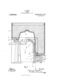
- Figure 1 is a vertical section of the pattern showing the stationary and movable pattern members, flask, and molding sand.
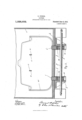
- Fig. 2 is a vertical section taken at right angles to Fig. 1
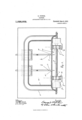
- Fig. 3 is a horizontal section on the line b?) Fig. 1. 1
- the pattern shown in the accompanying drawings comprises a stationary pattern member a forming the bowl and back of a. kitchen sink or lavatory, and this pattern member a is fixedly attached to the pattern block or follow board I), which, during the formation of the mold, forms the false part of the flask.
- the pattern member a is free from all horizontal projecting parts which would prevent the molding sand coming evenly into contact with it.
- the flask 0 is placed around the pattern member a, the bottom of the flask being seated upon the pattern block or follow board.
- the molding sand is then placed in the flask around the pattern, and the flask and pattern are jarred vertically as indicated by arrow in Fig.
- a slot 9 For the operation of the movable pattern member 0, I form in the stationary pat-tern member a, a slot 6, and I also form in the pattern block or follow board I), a slot 9, the end of the slot 9 engaging with a shoulder h on the movable pattern member to limit its outward movement beyond the surface of the stationary pattern member for the completion of the mold.
- the movable pattern member is retracted until it is wholly within the surface of the stationary pattern member a for the drawing of the pattern from the flask.
- a movable pattern member 2' which may be retracted within the stationary pattern member during the formation of the imprint therefrom, and then advanced into the molding sand when that imprint is finished in the same manner as the movable pattern member a, to complete the formation of the mold.
- this movable pattern member i is parallel with the line of impact, it is not absolutely necessary to retract it within the stationary pattern member a during the jarring of the pattern, and consequently it can be left in a projected position as shown in Fig. 1, until the mold is formed, and then retracted within the stationary pattern member for the separation of the mold and pattern.
- the movable pattern member is connected to a slide block j, having movement in slideways l0 fixed to the pattern block or follow board 6, and this slide block j is provided with an open strap Z for an eccentric m, mounted on a shaft 79, the eccentric m, during a semi-revolution of the shaft in the direction indicated by arrow, causing the retraction of the movable pattern member, and on the completion or reversal of that semi-revolution, again restoring the movable pattern member to its advanced position.
- the movable pattern member 0 is advanced to and retracted from its molding position, preferably manually, but it may be advanced and retracted mechanically by means such, for instance, as those used to advance and retract the movable pattern member 2.
- the principle of my invention may be briefly summarized as a pattern comprising a normally stationary pattern member and a pattern member movable with relation to the stationary member, to be advanced to a member a is normally stationary with rela-.
- a pattern for molds the combination of a stationary pattern member; a pattern block on which said member is supported provided with an elongated slot; and a longitudinally reciprocating pattern member extending beneath said block provided with a bent portion passing through said slot and with another portion extending above said block adapted to enter the sand of the mold, said bent portion adapted to contact with one of the walls of said slot and therefore limit its movement, substantially as described.
- a pattern for molds the combination of a stationary pat-tern member; a pattern block on which said member is supported provided with a slot a longitudinally reciprocating pattern member extending beneath said block provided with a bent portion passing through said slot and with another portion extending above said block adapted to enter the sand of the mold, said bent portion adapted to contact with one of the walls of said slot to limit its movement; and a second reciprocating member passing through said block adapted to be forced into the sand of the mold and to contact with an edge of said stationary pattern 'member, substantially as described.
- V H. T. BUSH Signed in the presence of V H. T. BUSH, V
Landscapes
- Engineering & Computer Science (AREA)
- Mechanical Engineering (AREA)
- Casting Devices For Molds (AREA)
Description
3 SHEETS-SHEET 1.
Patented June 4, 1912 PATTERN.
APPLICATION FILED NOV. 27, 1911.
E. PIPHER.
COLUMBIA PLANOGRAPH C0, WASHINGTON. D. c.
- E. PIPHER.
PATTERN.
APPLICATION FILED NOV. 27, 1911.
Patented June 4, 1912.
3 SHEBTSSHEET 2.
\\\\\\\\\\\\\\\\\\\\\\\\\\\\\\\\\\\\\\\\mmm E. PIPHER.
PATTERN.
APPLICATION FILED NOV. 27, 1911.
. 1 2 02 Patent ed June 4, 1912.
3 SHEETS-SHEET 3.
EDWARD PIPHER, OF PORT HOPE, ONTARIO, CANADA.
PATTERN.
Specification of Letters Patent.
Patented June 4., 1912.
Application filed November 27, 1911. Serial No. 662,730.
T 0 all whom it mayooncem Be it known that I, EDWARD PIPI-IER, a British subject, and resident of the town of Port Hope, in the county of Durham and Province of Ontario, Dominion of Canada, have invented certain new and useful Improvements in Patterns; and I hereby declare that the following is a full, clear, and exact description of the same.
Heretofore, in preparing a mold for the casting of a metal body with projecting parts, it has been customary to use a pattern with projecting members permanently aflixed to its mold forming surface, and it has also been customary to use a multi-part flask for the drawing of the pattern when the mold was formed. With the introduction of molding machinery, especially that class of molding machinery working on the jarring or vibrating principle, all at-- tempts failed to mechanically mold a pattern of this character, because the projecting members of the pattern impeded the packing of the sand, especially when such projecting members were angularly disposed to the line of impact. I
To overcome the difliculties of preparing a mold from a pattern having projecting members, is the object of my present invention, and this object is accomplished by the use of a stationary pattern member normally free from projecting members angularly disposed to the line of impact, so that the molding sand will'pack evenly against the stationary pattern member, and by the use of one or more movable pattern members normally contained within the stationary pattern member during the packing of the sand, and then projected beyond it to complete the formation of the mold cavity.
While the present invention can be used for preparing a mold for the casting of any metal body with projecting parts, I have, for the purpose of explaining its principle, hereinafter used as an example, a pattern for a kitchen sink or lavatory having lugs cast on its exterior surface.
For an understanding of my invention, reference is to be had to the following description and to the accompanying drawings, in which:
Figure 1, is a vertical section of the pattern showing the stationary and movable pattern members, flask, and molding sand. Fig. 2, is a vertical section taken at right angles to Fig. 1, and Fig. 3, is a horizontal section on the line b?) Fig. 1. 1
Like characters of reference refer to like parts throughout the specification and drawings.
The pattern shown in the accompanying drawings, comprises a stationary pattern member a forming the bowl and back of a. kitchen sink or lavatory, and this pattern member a is fixedly attached to the pattern block or follow board I), which, during the formation of the mold, forms the false part of the flask. As shown in the drawings, the pattern member a is free from all horizontal projecting parts which would prevent the molding sand coming evenly into contact with it. During the molding of the pattern, the flask 0 is placed around the pattern member a, the bottom of the flask being seated upon the pattern block or follow board. The molding sand is then placed in the flask around the pattern, and the flask and pattern are jarred vertically as indicated by arrow in Fig. 1, until the molding sand is packed tightly around the pat-tern to form an imprint in exact correspondence of the external surface of the pattern member. WVhen the imprint of the external sur face of the pattern member a is made, a movable pattern member 0 is projected beyond the external surface of the pattern a to complete the formation of the mold cavity by forming, in the molding sand, the imprint for the casting of the projecting part of the metal body.
For the operation of the movable pattern member 0, I form in the stationary pat-tern member a, a slot 6, and I also form in the pattern block or follow board I), a slot 9, the end of the slot 9 engaging with a shoulder h on the movable pattern member to limit its outward movement beyond the surface of the stationary pattern member for the completion of the mold. When the mold is formed, the movable pattern member is retracted until it is wholly within the surface of the stationary pattern member a for the drawing of the pattern from the flask. By this means, I am able, by jarring 0r vibrating the pattern and flask, to mold an imprint of the stationary pattern member and then mold an imprint of the movable pattern member or members angular to the line of impact resulting from the jar or vibration, and I am also able, upon the retraction of the movable pattern member or members within the stationary pattern member, to effect the separation of the mold from the pattern without injury to the imprint.
For the formation of a lug in parallel relation to the line of impact, as indicated by arrow in Fig. 1, I may use a movable pattern member 2', which may be retracted within the stationary pattern member during the formation of the imprint therefrom, and then advanced into the molding sand when that imprint is finished in the same manner as the movable pattern member a, to complete the formation of the mold. As this movable pattern member i is parallel with the line of impact, it is not absolutely necessary to retract it within the stationary pattern member a during the jarring of the pattern, and consequently it can be left in a projected position as shown in Fig. 1, until the mold is formed, and then retracted within the stationary pattern member for the separation of the mold and pattern. For its retraction, the movable pattern member is connected to a slide block j, having movement in slideways l0 fixed to the pattern block or follow board 6, and this slide block j is provided with an open strap Z for an eccentric m, mounted on a shaft 79, the eccentric m, during a semi-revolution of the shaft in the direction indicated by arrow, causing the retraction of the movable pattern member, and on the completion or reversal of that semi-revolution, again restoring the movable pattern member to its advanced position.
The movable pattern member 0 is advanced to and retracted from its molding position, preferably manually, but it may be advanced and retracted mechanically by means such, for instance, as those used to advance and retract the movable pattern member 2.
The principle of my invention may be briefly summarized as a pattern comprising a normally stationary pattern member and a pattern member movable with relation to the stationary member, to be advanced to a member a is normally stationary with rela-.
tion to the pattern members 0 and 2', and the pattern members 0 andz' are movable with relation to the pattern member a. 7
Having thus fully described the nature of my invention, what I claim as new and desire to secure by Letters Patent, is:
1. In a pattern for molds, the combination of a stationary pattern member; a pattern block on which said member is supported provided with an elongated slot; and a longitudinally reciprocating pattern member extending beneath said block provided with a bent portion passing through said slot and with another portion extending above said block adapted to enter the sand of the mold, said bent portion adapted to contact with one of the walls of said slot and therefore limit its movement, substantially as described.
2. In a pattern for molds, the combination of a stationary pat-tern member; a pattern block on which said member is supported provided with a slot a longitudinally reciprocating pattern member extending beneath said block provided with a bent portion passing through said slot and with another portion extending above said block adapted to enter the sand of the mold, said bent portion adapted to contact with one of the walls of said slot to limit its movement; and a second reciprocating member passing through said block adapted to be forced into the sand of the mold and to contact with an edge of said stationary pattern 'member, substantially as described.
Port Hope, November 1st, 1911.
EDWARD PIPHER.
Signed in the presence of V H. T. BUSH, V
C. H. Rrorrns.
Copies of this patent-may be obtained for five cents each, by addressingflthe Commissioner of Patents,
Priority Applications (1)
| Application Number | Priority Date | Filing Date | Title |
|---|---|---|---|
| US66273011A US1028602A (en) | 1911-11-27 | 1911-11-27 | Pattern. |
Applications Claiming Priority (1)
| Application Number | Priority Date | Filing Date | Title |
|---|---|---|---|
| US66273011A US1028602A (en) | 1911-11-27 | 1911-11-27 | Pattern. |
Publications (1)
| Publication Number | Publication Date |
|---|---|
| US1028602A true US1028602A (en) | 1912-06-04 |
Family
ID=3096895
Family Applications (1)
| Application Number | Title | Priority Date | Filing Date |
|---|---|---|---|
| US66273011A Expired - Lifetime US1028602A (en) | 1911-11-27 | 1911-11-27 | Pattern. |
Country Status (1)
| Country | Link |
|---|---|
| US (1) | US1028602A (en) |
-
1911
- 1911-11-27 US US66273011A patent/US1028602A/en not_active Expired - Lifetime
Similar Documents
| Publication | Publication Date | Title |
|---|---|---|
| US266532A (en) | Brick-press | |
| US8158A (en) | Mahlon gregg | |
| US1224687A (en) | Mold for making dental-crown dies. | |
| US820458A (en) | Cement block and post machine. | |
| US4803A (en) | Improvement in making molds for castings | |
| US346380A (en) | Matthew robert moore | |
| US3169A (en) | Improvement in molds for castingiwagon-boxes | |
| US177395A (en) | Improvement in molder s flasks | |
| US130900A (en) | Improvement in niqldlnos | |
| US915489A (en) | Molding-box and the like. | |
| US469747A (en) | Core-seat for pipe-flasks | |
| US900633A (en) | Molding-machine. | |
| US841080A (en) | Fence-post mold. | |
| US3435A (en) | Improvement in molds for butt-hinges | |
| US185197A (en) | Improvement in machines for pressing molten metal into ingots | |
| US1069383A (en) | Molding-machine. | |
| US956939A (en) | Molding apparatus. | |
| US375313A (en) | comers | |
| US968799A (en) | Sprue. | |
| US951861A (en) | Molding apparatus. | |
| US975159A (en) | Molding-flask sliding hinge. | |
| US769959A (en) | Apparatus for molding sash-weights. | |
| US618080A (en) | farwell | |
| US774648A (en) | Device for compressing and opening cigar-molds. | |
| US865071A (en) | Molding-machine. |