US185197A - Improvement in machines for pressing molten metal into ingots - Google Patents
Improvement in machines for pressing molten metal into ingots Download PDFInfo
- Publication number
- US185197A US185197A US185197DA US185197A US 185197 A US185197 A US 185197A US 185197D A US185197D A US 185197DA US 185197 A US185197 A US 185197A
- Authority
- US
- United States
- Prior art keywords
- mold
- ingots
- piston
- pressing
- molds
- Prior art date
- Legal status (The legal status is an assumption and is not a legal conclusion. Google has not performed a legal analysis and makes no representation as to the accuracy of the status listed.)
- Expired - Lifetime
Links
- 239000002184 metal Substances 0.000 title description 10
- 229910052751 metal Inorganic materials 0.000 title description 10
- 238000010276 construction Methods 0.000 description 4
- 238000005266 casting Methods 0.000 description 3
- XEEYBQQBJWHFJM-UHFFFAOYSA-N Iron Chemical compound [Fe] XEEYBQQBJWHFJM-UHFFFAOYSA-N 0.000 description 2
- 238000009408 flooring Methods 0.000 description 1
- 229910052742 iron Inorganic materials 0.000 description 1
- 238000004519 manufacturing process Methods 0.000 description 1
- 238000000926 separation method Methods 0.000 description 1
Images
Classifications
-
- B—PERFORMING OPERATIONS; TRANSPORTING
- B22—CASTING; POWDER METALLURGY
- B22D—CASTING OF METALS; CASTING OF OTHER SUBSTANCES BY THE SAME PROCESSES OR DEVICES
- B22D18/00—Pressure casting; Vacuum casting
- B22D18/02—Pressure casting making use of mechanical pressure devices, e.g. cast-forging
Definitions
- My invention relates to machinery for producing pressed cast-metal ingots and castings of different kinds and forms for use in the arts, in the forms given to them by themolds and the nature of my invention consists in certain constructions, arrangements, and c0mbinations of parts, hereinafter described and specifically claimed.
- Ame presents the flooring of a building, B, a short metal platform with side guides or flanges a.
- This platform is firmly fastened imposi- -tion in any convenient manner. 0 is aforked.
- the ratchet G serves as a means by which to turn the shaft and pinion.
- This ratchet is provided with a double-acting pawl, pivoted centrally above it to a hand-lever, H, so as to be capable of rocking.
- a hand-lever, H By throwing up one end of this pawl the other will take into the teeth of the ratchet in rear of the shaft, and thereby become adjusted for feeding the mold- .bed in one direction, and by throwing up the opposite end of the pawl .its other end will take into the ratchet in front of the shaft, and the machine thereby become adjusted for feedingthe mold-bed in a reverse direction.
- the adjustment of the pawl is made with the hand or by a rod, and the movement of the shaft is effected by vibrating the handthe-respective gage-stop holes d at the moment one on the molds is fed centrally under thepressiug-piston, and locks. the mold-bed during the descendingoperation of the piston. The stop-pin is moved out of the holes by hand, and into the same by the springf.
- the molds represented are made in two-vertically-divided halves, and with removable or false bottoms, and onthetop of each of these bottoms a projection, ,h, corresponding in size to :the interior of the mold, is formed, and Over thisprojection .the body of the mold fits snugly.
- the molds might be madein one piece, with their bottoms immovable but I prefer the plan shown.
- lugs m m are formed, and corresponding lugs may be formed on the false or removable bottoms.
- J J are vertical screw or key bolts, secured to the mold-bed in close proximity to the lugs m m. On these bolts clamps a n are placed loosely, so as to turn on the bolts.
- the molds can be securely fastened upon the bed, and the joint between the bottoms and the body of the mold made tight when detachable bottoms are used.
- the turning up of the J and the-parts are united to one another by a tapering dovetail tongue, 19, on one part,
- the form shown may be substituted by any other de sired form, according to the form of the mold used, and the union and separation of the parts J and J may be effected without the trouble of withdrawing and inserting keys or pins, and without moving the part J downward.
- the piston-rod is made of round iron, as this metal costs less to produce it, and is used with greater economy in the manufacture of the power-machine, as the cylinderheads and stuffing-boxes can all be bored out.
- the first of the series of molds is sufficiently filled with metal to form an ingot or casting, and moved (by Working the ratchet-lever) toward and under the pressingpiston until the spring locking-pin falls into the first stop-hole.
- the cut-ofi' valve N is then opened and a powerful hydraulic pressure allowed to act on the top of the piston of the cylinder M until the pressing-piston has descended far enough in the mold to shape and condense molten metal into an ingot or casting, as the case may be.
- the hydraulic pressure is now cut off and the piston raised by the admission of hydraulic pressure below it.
- the second mold of the series is filled, and as soon as the metal in the first mold is operated upon and the pressing-head withdrawn, the bed is unlocked and moved along, by working the ratchet-lever, until the second mold takes its place and becomes locked,
- the pawl is adjusted so as to take into theteeth of the ratchet on the opposite side of the ratchetchine, the reciprocating bed having a plurality of molds arranged upon it, in combination with a guiding and supporting platform, and a pressing-piston of a hydraulic cylinder placed above the bed, substantially as described.
Landscapes
- Engineering & Computer Science (AREA)
- Mechanical Engineering (AREA)
- Molds, Cores, And Manufacturing Methods Thereof (AREA)
Description
- Z-Sheets-Sheetl.
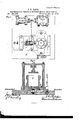
- Jl-B. FARR. MACHINE-FOR PRESSING MOLTEN METAL INTO-INGOTS. No."185,'197, Patented Dec. 12, 1876.
THE GRAPHIC, CO.N.Y.
2 S1i eet '-Shegt 2..
INTO mews. ed Dec. 12, 1876.
TAL
tent.
V .1. B. mm. MACHINE FORPRESSING MOLI'EN ME No. 185,197. Pa.
UNITED STATES PATENT Feta.
JOHN BLAKE TARR, OF FAIR HAVEN, MASSACHUSETTS.
IMPROVEMENT lN MACHINES-FOR PRESSING MOLTEN'METAL INTO INGOTS.
Specification forming part of Letters Patent No. [85,197, dated December 12, 1876; application filed May 24, 1876.
To all whom it may concern:
Be it known that I, JOHN BLAKE TARR, of Fair Haven, in the county of Bristol and State of Massachusetts, have invented certain new and useful Improvements in Machines for Pressing Molten Metal into Ingots and other Forms; and I do hereby declare that the following is a full, clear, and exact description of the same, reference being had to the accompanying drawings, forming. part of this specification, in which- Figure l is a vertical longitudinal section ofthe machine; Fig. 2. a horizontal section of the same in the line 00 m of Fig. 3. Fig. 3 is a plan view of the whole machine. Fig. 4 is a vertical cross-section of the same in the line y y of Fig. 2. Fig. 5 is a detail view of the reversing pawl-and-ratchet feed-movement.
My invention relates to machinery for producing pressed cast-metal ingots and castings of different kinds and forms for use in the arts, in the forms given to them by themolds and the nature of my invention consists in certain constructions, arrangements, and c0mbinations of parts, hereinafter described and specifically claimed.
To enable others skilled in the art to understand my invention, I willproceed to describe it.
In the accompanying drawings, Amepresents the flooring of a building, B, a short metal platform with side guides or flanges a.
a. This platform is firmly fastened imposi- -tion in any convenient manner. 0 is aforked.
of the rack, and moves it back and forth, and
the ratchet G serves as a means by which to turn the shaft and pinion. This ratchetis provided with a double-acting pawl, pivoted centrally above it to a hand-lever, H, so as to be capable of rocking. By throwing up one end of this pawl the other will take into the teeth of the ratchet in rear of the shaft, and thereby become adjusted for feeding the mold- .bed in one direction, and by throwing up the opposite end of the pawl .its other end will take into the ratchet in front of the shaft, and the machine thereby become adjusted for feedingthe mold-bed in a reverse direction.
The adjustment of the pawl is made with the hand or by a rod, and the movement of the shaft is effected by vibrating the handthe-respective gage-stop holes d at the moment one on the molds is fed centrally under thepressiug-piston, and locks. the mold-bed during the descendingoperation of the piston. The stop-pin is moved out of the holes by hand, and into the same by the springf.
v The molds represented are made in two-vertically-divided halves, and with removable or false bottoms, and onthetop of each of these bottoms a projection, ,h, corresponding in size to :the interior of the mold, is formed, and Over thisprojection .the body of the mold fits snugly.
The molds might be madein one piece, with their bottoms immovable but I prefer the plan shown.
At the base of each mold, on two;sides, lugs m m are formed, and corresponding lugs may be formed on the false or removable bottoms.
J J are vertical screw or key bolts, secured to the mold-bed in close proximity to the lugs m m. On these bolts clamps a n are placed loosely, so as to turn on the bolts.
By means of the lugs, clamps, and bolts the molds can be securely fastened upon the bed, and the joint between the bottoms and the body of the mold made tight when detachable bottoms are used. The turning up of the J and the-parts are united to one another bya tapering dovetail tongue, 19, on one part,
and a corresponding dovetail groove,p, on the other, or by a T-head connection, which permits the part J to be moved laterally out of connection with the part J. 'By this construction of the pressing-piston the form shown may be substituted by any other de sired form, according to the form of the mold used, and the union and separation of the parts J and J may be effected without the trouble of withdrawing and inserting keys or pins, and without moving the part J downward. The piston-rod is made of round iron, as this metal costs less to produce it, and is used with greater economy in the manufacture of the power-machine, as the cylinderheads and stuffing-boxes can all be bored out. While, therefore, I use a round piston-rod, I make one side, 10, of it fiat by planing off a portion of its surface; and I also plane out the bore of the stuffing-box and head of the cylinder to a form which will match the piston-rod. By this construction I provide a perfect guide for the piston, and am enabled to use molds with many sides, and have the piston enter them with unerring ac curacy. The piston-rod extends up into an hydraulic cylinder, M, mounted on a suitable frame. The cylinder is furnished with a suitablc cut-ofi" valve, N, which is connected with a pump, 0, of any suitable known construction, and worked by a steam-engine, as illus-' trated in the drawings, or in any other proper manner.
Operation: The first of the series of molds is sufficiently filled with metal to form an ingot or casting, and moved (by Working the ratchet-lever) toward and under the pressingpiston until the spring locking-pin falls into the first stop-hole. The cut-ofi' valve N is then opened and a powerful hydraulic pressure allowed to act on the top of the piston of the cylinder M until the pressing-piston has descended far enough in the mold to shape and condense molten metal into an ingot or casting, as the case may be. The hydraulic pressure is now cut off and the piston raised by the admission of hydraulic pressure below it. During the pressing operation, or at its completion, the second mold of the series is filled, and as soon as the metal in the first mold is operated upon and the pressing-head withdrawn, the bed is unlocked and moved along, by working the ratchet-lever, until the second mold takes its place and becomes locked,
- when the pressing operation just described is repeated. The same operation takes place in bringing the third mold under the pressingpiston. To reverse the movement of the bed after the filled molds are removed and other empty molds placed upon it, the pawl is adjusted so as to take into theteeth of the ratchet on the opposite side of the ratchetchine, the reciprocating bed having a plurality of molds arranged upon it, in combination with a guiding and supporting platform, and a pressing-piston of a hydraulic cylinder placed above the bed, substantially as described.
2. The combination of a bed, a plurality of molds, a supportingplatform, a pinion, a ratchet, a double-acting pawl, stop-holes, a spring locking-pin, and a pressing-piston, substantially as described.
3. The combination of the short supportingplatt'orm, long mold-bed, having a series of molds upon it, the separated support, and the single pressing-piston, substantially as described. r
4. The bed with centering cavities, in combination with bottoms of molds, having corresponding projections for entering the cavities, substantially as'described.
5. The molds with removable bottoms, having top and bottom projections c and h, for fitting, respectively, into the body of the mold and into the bed thereof, substantially as detion with a mold having many sides, substantially as described.
JOHN BLAKE TARR. Witnesses:
JAMES MARTIN, J r., G. H. MoUL'roN.
Publications (1)
| Publication Number | Publication Date |
|---|---|
| US185197A true US185197A (en) | 1876-12-12 |
Family
ID=2254602
Family Applications (1)
| Application Number | Title | Priority Date | Filing Date |
|---|---|---|---|
| US185197D Expired - Lifetime US185197A (en) | Improvement in machines for pressing molten metal into ingots |
Country Status (1)
| Country | Link |
|---|---|
| US (1) | US185197A (en) |
-
0
- US US185197D patent/US185197A/en not_active Expired - Lifetime
Similar Documents
| Publication | Publication Date | Title |
|---|---|---|
| US185197A (en) | Improvement in machines for pressing molten metal into ingots | |
| US266532A (en) | Brick-press | |
| US2017784A (en) | Cold press | |
| US943971A (en) | Machine for making cement tiles. | |
| US5466A (en) | Lead-pipe machiiteby | |
| US1000204A (en) | Briquet-press. | |
| US383084A (en) | Machine for forming eyes on rods | |
| US698596A (en) | Casting-machine. | |
| US434031A (en) | Die for compressing soap around an anchor | |
| US29036A (en) | Isaac m | |
| US436929A (en) | Die for brick or tile machines | |
| US1020297A (en) | Method for forming dies. | |
| US419749A (en) | Steam brick-machine | |
| US50791A (en) | Improved machine for molding potter s ware | |
| US657174A (en) | Manufacture of dovetailed tiles. | |
| US386724A (en) | simpson | |
| US1519844A (en) | Mold conveyer | |
| US809250A (en) | Cement-brick machine. | |
| US494911A (en) | Brick-machine | |
| US1190475A (en) | Brick-machine. | |
| US1147364A (en) | Machine for making nut-blanks. | |
| USRE3251E (en) | Improvement in bolt-making- machines | |
| US737032A (en) | Mold for concrete blocks. | |
| US1260745A (en) | Power-hammer. | |
| US8570A (en) | Improved foundry apparatus |