US1027357A - Wire-drawing block. - Google Patents
Wire-drawing block. Download PDFInfo
- Publication number
- US1027357A US1027357A US57040210A US1910570402A US1027357A US 1027357 A US1027357 A US 1027357A US 57040210 A US57040210 A US 57040210A US 1910570402 A US1910570402 A US 1910570402A US 1027357 A US1027357 A US 1027357A
- Authority
- US
- United States
- Prior art keywords
- drum
- cable
- wire
- plate
- block
- Prior art date
- Legal status (The legal status is an assumption and is not a legal conclusion. Google has not performed a legal analysis and makes no representation as to the accuracy of the status listed.)
- Expired - Lifetime
Links
Images

Classifications
-
- B—PERFORMING OPERATIONS; TRANSPORTING
- B21—MECHANICAL METAL-WORKING WITHOUT ESSENTIALLY REMOVING MATERIAL; PUNCHING METAL
- B21C—MANUFACTURE OF METAL SHEETS, WIRE, RODS, TUBES, PROFILES OR LIKE SEMI-MANUFACTURED PRODUCTS OTHERWISE THAN BY ROLLING; AUXILIARY OPERATIONS USED IN CONNECTION WITH METAL-WORKING WITHOUT ESSENTIALLY REMOVING MATERIAL
- B21C1/00—Manufacture of metal sheets, wire, rods, tubes or like semi-manufactured products by drawing
- B21C1/02—Drawing metal wire or like flexible metallic material by drawing machines or apparatus in which the drawing action is effected by drums
- B21C1/12—Regulating or controlling speed of drawing drums, e.g. to influence tension; Drives; Stop or relief mechanisms
Definitions
- the present invention relates to blocks utilized during the process of making wire for the purpose of drawing a wire rod through a die block, and for'winding the wire after the drawing operation.
- the objects of the present invention are to construct a block wherebyuponthe ini tial operation thereof, the cable carrying the grippers clamping theend of the wire will advance with a relatively slow movement and will increase its speed of movement asthe block is rotated a greater distance.
- a further object of the invention is to place the cable under a tension prior to the starting of the block, whereby the grippers upon the end of the cable will tightly clamp the end of the wire.
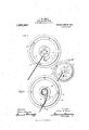
- Figure 1 is a plan view of the block, showing the cable in its posi-- tion when the end thereof is attached to the wire and before the block has started re-o volving;
- Fig. 1 a viewshowing the cable prior to its being moved into position to have the grippers engage the end of the wire;
- Fig. 2 a plan view showing the block after it has been rotated a distance;
- Fig- 3 a plan view of the block, showing the parts in position after the block has rotated sufficiently to carry the cable onto theoutside of the drum;
- Fig.” 4 a cross section of the block.
- the rod which is to be drawn through the die block is tapered at its end intoan elongated point, so that the body of the wire is gradually drawn into contact with the die. This is necessary because of the fact that if the funcircumference of the rod were suddenly brought into contact with the die opening,
- the resultant shockor jar would tear the rod at the point where it was in engagement with the die.
- the full diameter of the rod is not brought into contact with the die upon the I initial movement of the rod through the'die,
- the block of the present invention comprises a body portion in'the form of a drum 5, havingits exterior of stepped formation,
- the drum is provided in its upper portion with a centrally disposed chamber 6, in which lies a spring 7.
- a spring is attached to a stud 8 carried by the drum, and the other end is attached to a stud 9 carriedby a plate 10 lying upon the upper face llof the block.
- the plate 10 is provided with a collar 10, which surrounds an upwardly extending spindle 12"secured to the body of the drum, whereby rotative action of the spindle will rotate the drum and vertical movement of the plate 10 around the spindle 12 is prevented by means of a cotter pin 13, or other suitablelocking device.
- the plate 10 is provided with a member 14 inthe' form of a staple, to'which is attached a cable 15, having upon the free end thereof grippers 16 of any suitable'and well known character for gripping the end of the wire.
- the plate 10 is also provided with an outwardly extending contact 17 and the drum 5 is provided, upon its upper face, with a lug 18, which forms a contact adapted to engage the contact 17 of the plate 10.
- a loose ring 19 Within a groove 18 in the upper outer edge of the block is positioned a loose ring 19,
- the ring 19 is provided with a plurality of recesses, adapted to receive upwardly extending rods 22, around which the wire is reeled after a sufficient amount has been gathered upon the drum to entirely cover the body portion thereof.
- the drum is rotated from the position-shown in Fig. 1 to that shown in Fig. 2, if the end of the ring is brought in contact with the cable it simply slides around on the drum since the pressure is approximately in the direction of a tangent to the ring. IVhen, however, the cable is deflected by the contact 18 the line of pressure produces a secant or radius of the ring and the friction between the drum and ring is thereby increased to such an extent 1 that the ring is carried around with the drum and the cable wound on the ring. Due to the greater distance of the ring from the center of the drum the speed of movement of the cable is increased over that given it by the action of the contact 18.
- the contact 18 and the collar 10 are so arranged with respect to one another that when the cable is engaged respectively by this contact and deflected fromits course around the collar 10*, it will describe an increasing arc toward the outer periphery of the block, so that the speed of movement of the wire through the block will be increased as the block continues to rotate.
- the chain upon the initial rotation of the block, the chain will be advanced but a relatively short distance and the speed of movement of the cable is increased until it is moving at the same speed as the block; and this is the movement desired and necessary in order to properly advance the wire through the dies without breaking or cutting the end thereof during such operation, orv without subjecting the die and rod to the violent strain incident to the quick forcing of the enlarged portion into the dies.
- a wire drawing block the combination of a rotatable drum, a spindle upwardly extending from the drum, a plate having a collar surrounding said spindle and lying upon the upper surface of said drum, a cable attached to said plate, having grippers on the end thereof adapted to clamp the end of the wire, a member carried by the drum for engaging and rotating said plate, whereby upon the initial movement of the drum the cable is wound about the collar, said engaging means serving to deflect the cable from its path of travel about the collaredportion of the plate, to carry it to the outside of the drum, whereby the speed of winding of the cable is increased during the initial period of movement of the plate, tension means for placing a spring tension on the plate to cause the grippers to obtain an initial firm grip on the wire prior to the rotation of the drum, and means for deflecting the cable to place the grippers upon the outside of the drum, substantially as described.
- a wire drawing block the combina tion of a rotatable drum, a spindle upwardly extending from the drum, a collared plate surrounding said spindle and lying upon the upper surface of said drum, a cable attached to said plate, having grippers on the end thereof adapted to clamp the end of the wire, a protuberance on said plate, a proturbance on said drum adapted to engage each other, the cable upon the initial movement of the drum being wound in a curve of small radius about said collar, said proturberance deflecting the cable from its path of travel about said collar to carry it to the outside of the drum, whereby the speed of winding of the cable is increased during the initial period of movement of the drum, substantially as described.
- a rotatable drum a spindle upwardly extending fromthe center of the drum, a plate having a collar surrounding said spindle and operatively connected to the drum, a cable attached to said plate, having grippers on the end thereof adapted to clamp the end of the wire, the initial rotation of the plate winding the cable about the collar.
- 1116111181 01 deflecting the cable from its path of travel.
- a rotatable drum a spindle upwardly extending from the center of the drum, a plate having a collar surrounding said spindle and operatively connected to the drum, a cable attached to said plate having grippers on the end thereof adapted to clamp the end of the wire, a protuberance on said plate, a protuberance on saiddrum adapted to engage each other, the cable upon the initial'inovementof the drum being wound about the collar, said.
- drum protuberance deflecting the cable from its path of travel about the collar, whereby the speed of winding of the cable is increased, and a loosely mounted ring on the drum at its periphery having a portion thereof cut away to "permit the cable to pass out and to provide a shoulder adapted to engage the cable and prevent the slipping of the cable over the top of the drum, sub stantially as described.
- a rotatable drum a spindleup-' wardly extending from the center of the drum, a plate having a collar surrounding said spindle and operatively connected to the drum, a cable attached to said plate,
- a rotatable drum a spindle upwardly extending from the center of the drum, a platehaving a collar surrounding said spindle and operatively connected to said drum, a cable attached to said plate, having grippers onthe end thereof adapted to clamp the end of the wire, the initial rotation of the plate winding the cable around the collar, means for deflecting the cable from its path of travel about the col-' lar, whereby the speed of winding of the cable is increased during the initial period of movementof the drum, said drum having a centrally located recess therein, a spring within said recess, having one end attached to the plate and the other end attached to said drum, said spring serving to place a tension on said plate prior to the initial movement of the drum, whereby the grippers on the cable are held in firm engagement with the end of the wire, substantially as described.
- a rotatable drum a spindleupwardly extending from the center of the drum, a plate having a collar surrounding said spindle, and operatively connected to said drum, a cable attached to said plate,
- a wire drawing block the combination of a rotatable drum, a spindle upwardly extending from the drum, a collared plate member loosely mounted on said spindle, and operatively connected to the drum, a cable secured to said member, said cable having grippers on the end thereof adapted to clamp the end of the wire, the initial movement of the "drum carrying the cable in a circle of small radius about said member, means for deflecting the cable to carry it out from its initial path of movement and onto the outside of the drum, sub stantially as described.
- a wire drawing block the combination of a rotatable drum, a spindle upwardly extending from the drum, a member loosely mounted on said spindle and operatively connected to the drum, a cable secured to said member, said cable having grippers on the end thereof adapted to clamp the end of the wire, the initial move ment of the drum carrying the cable in a circle of small radius about said member, means for deflecting the cable from its initial movement to carry it onto the outside of the drum, and means for placing an initiatory spring tension on said member to enable the grippers on the cable to obtain an initial firm grip on the wire prior to the rotation of the drum, substantially as described.
- a wire drawing block the combination of a rotatable drum, a spindle upwardly extending from the drum, a collared plate loosely mounted upon said spindle and operatively connected to said drum, said plate lying against the upper face of said drum, a cable attached to said plate, having grippers on the end thereof adapted to clamp the end of the wire, whereby upon the initial movement of the drum the cable is wound about the collared portion of the plate to carry it to the outside of the drum, whereby the speed of winding the cable is increased during the initial period of movement of the drum, substantially as described.
Landscapes
- Engineering & Computer Science (AREA)
- Mechanical Engineering (AREA)
- Storage Of Web-Like Or Filamentary Materials (AREA)
Description
J. H. REF-GE.
WIRE DRAWING BLOCK. APPLICATION FILED JULY 5, 1910.
l atented May 21, 1912.
2 SHEETS-SHEET 1.
Inventor:
mzllessesr Jzzan H. Reece.
COLUMBIA PLANDGRAPH c0.,wASl-IINOTON, D. c.
J. H. REEGE.
WIRE DRAWING BLOCK. APPLICATION Hum 1111.15, 1910.
1,027,357, V .Patented May 21,fl19 l2.
z snnn'rs-snnnic 2.
h l'znesses [/2 yen for:
COLUMBIA PLANOGRAPH co.,wAsmNnTpN, D. C, I
UNITED STATES PATENT OFFICE. I v
JUAN H. REECE, 0F JOLIET, ILLINOIS, ASSIGNOR T0 HUMPI-IREY & SONS, OF OLIET, ILLINOIS, .A. COPARTNERSHIP.
WIRE-DRAWING BLOCK.
Specification of Letters Patent.
Patented May 21, 1912.
To all whom it may concern: 7 Be it known that I, JUAN H. Enron, a c1t1- zen of the United States, residing at J oliet,
in the county of Will and State of Illinois, have invented certain new and useful Improvements in Wire-Drawing Blocks, of which the following is a specification.
The present invention relates to blocks utilized during the process of making wire for the purpose of drawing a wire rod through a die block, and for'winding the wire after the drawing operation.
The objects of the present invention are to construct a block wherebyuponthe ini tial operation thereof, the cable carrying the grippers clamping theend of the wire will advance with a relatively slow movement and will increase its speed of movement asthe block is rotated a greater distance.
A further object of the invention is to place the cable under a tension prior to the starting of the block, whereby the grippers upon the end of the cable will tightly clamp the end of the wire. 1
Further objects of the invention will appear from a detailed decription hereinafter set forth. e
In the drawings, Figure 1 is a plan view of the block, showing the cable in its posi-- tion when the end thereof is attached to the wire and before the block has started re-o volving; Fig. 1 a viewshowing the cable prior to its being moved into position to have the grippers engage the end of the wire; Fig. 2, a plan view showing the block after it has been rotated a distance; Fig- 3, a plan view of the block, showing the parts in position after the block has rotated sufficiently to carry the cable onto theoutside of the drum; and Fig." 4, a cross section of the block. c
In the art of wire drawing, the rod which is to be drawn through the die block is tapered at its end intoan elongated point, so that the body of the wire is gradually drawn into contact with the die. This is necessary because of the fact that if the funcircumference of the rod were suddenly brought into contact with the die opening,
the resultant shockor jar would tear the rod at the point where it was in engagement with the die. Hence, by utilizing a tapered end, the full diameter of the rod is not brought into contact with the die upon the I initial movement of the rod through the'die,
but this is gradually led up to, so that when thefull circumference of the rod is finally drawn between the die blocks, the strain incident thereto has been gradually imparted to the rod, so that it will not become broken when the full strain is placed thereon.
As the grippers, which are carried by the cable actuated by the drum, are secured to the extreme tapered end of the wire, it is obvious that it would not be practicable to subject them, upon the initial windingof the drum, to the full strain incident to the passing of the rod through the dies. Therefore, it isexpedient in these devices to start the block with a relatively slow movement and increase the same as the taper is drawn through the die. In this manner, the strain is graduallyincreased between the grippers and the wire, so that. a cutting of the wire by the grippers, ora loosening therefrom by other means, is not resultant upon the starting of the block.
The block of the present invention comprises a body portion in'the form of a drum 5, havingits exterior of stepped formation,
as is usual and well known in constructions:
of this nature, and the drum is provided in its upper portion with a centrally disposed chamber 6, in which lies a spring 7. One end of the spring is attached to a stud 8 carried by the drum, and the other end is attached to a stud 9 carriedby a plate 10 lying upon the upper face llof the block. The plate 10 is provided with a collar 10, which surrounds an upwardly extending spindle 12"secured to the body of the drum, whereby rotative action of the spindle will rotate the drum and vertical movement of the plate 10 around the spindle 12 is prevented by means of a cotter pin 13, or other suitablelocking device.
The plate 10 is provided with a member 14 inthe' form of a staple, to'which is attached a cable 15, having upon the free end thereof grippers 16 of any suitable'and well known character for gripping the end of the wire. The plate 10 is also provided with an outwardly extending contact 17 and the drum 5 is provided, upon its upper face, with a lug 18, which forms a contact adapted to engage the contact 17 of the plate 10. Within a groove 18 in the upper outer edge of the block is positioned a loose ring 19,
which is cut away to provide an opening :20, through which the cable passes from the block'to the wire coming from the die, and the shoulders 21 form a guide to insure the passing of the cable to the outside of the block, as will be more fully hereinafter set forth.
The ring 19 is provided with a plurality of recesses, adapted to receive upwardly extending rods 22, around which the wire is reeled after a sufficient amount has been gathered upon the drum to entirely cover the body portion thereof.
The operation is as follows: In the initial position, when the plate 10 is lying to have the protuberance 17 in the position shown in Fig. 1 the cable is grasped by the operator and the plate turned to the position shown in Fig. 1. This rotating of the plate will serve to wind up the sprmg 7, thus placing the plate 10 and cable 15 carried thereby under a tension. hen such tension has been produced, the grippers are secured to the end of the wire and will be held in place thereon, because of the constant inward pull of the cable produced by the tension of the spring 7. The drum is then rotated, and upon the initial movement of the drum, the cable will move into the position shown in Fig. 2, where .it is wound around the collar 10 thus, although the drum has advanced a considerable distance, the cable will have advanced but a short distance, because of the fact that it is wound on an arc of relatively short radius. That is, it is being carried through a path relatively close to the axial center of the drum; hence, the movement of the drum will impart but a very slight relative movement to the cable, and, of course, will advance the wire through the die blocks slowly. This slight movement of the cable will continue until the contact 18 crosses the path in which the chain is lying. hen said contact crosses said path, .it will engage and deflect the cable, carrying it around the axis of the drum in an arc of greater radius than the collar 10. Hence the'movement of the cable after it has been engaged by the contact 18 will be greater than when it was being revolved by the action of the plate 10, and the speed of movement of the wire through the die block increased.
hen the drum is rotated from the position-shown in Fig. 1 to that shown in Fig. 2, if the end of the ring is brought in contact with the cable it simply slides around on the drum since the pressure is approximately in the direction of a tangent to the ring. IVhen, however, the cable is deflected by the contact 18 the line of pressure produces a secant or radius of the ring and the friction between the drum and ring is thereby increased to such an extent 1 that the ring is carried around with the drum and the cable wound on the ring. Due to the greater distance of the ring from the center of the drum the speed of movement of the cable is increased over that given it by the action of the contact 18.
The contact 18 and the collar 10 are so arranged with respect to one another that when the cable is engaged respectively by this contact and deflected fromits course around the collar 10*, it will describe an increasing arc toward the outer periphery of the block, so that the speed of movement of the wire through the block will be increased as the block continues to rotate. Hence, upon the initial rotation of the block, the chain will be advanced but a relatively short distance and the speed of movement of the cable is increased until it is moving at the same speed as the block; and this is the movement desired and necessary in order to properly advance the wire through the dies without breaking or cutting the end thereof during such operation, orv without subjecting the die and rod to the violent strain incident to the quick forcing of the enlarged portion into the dies.
I claim:
1. In a wire drawing block, the combination of a rotatable drum, a spindle upwardly extending from the drum, a plate having a collar surrounding said spindle and lying upon the upper surface of said drum, a cable attached to said plate, having grippers on the end thereof adapted to clamp the end of the wire, a member carried by the drum for engaging and rotating said plate, whereby upon the initial movement of the drum the cable is wound about the collar, said engaging means serving to deflect the cable from its path of travel about the collaredportion of the plate, to carry it to the outside of the drum, whereby the speed of winding of the cable is increased during the initial period of movement of the plate, tension means for placing a spring tension on the plate to cause the grippers to obtain an initial firm grip on the wire prior to the rotation of the drum, and means for deflecting the cable to place the grippers upon the outside of the drum, substantially as described.
2. In a wire drawing block, the combina tion of a rotatable drum, a spindle upwardly extending from the drum, a collared plate surrounding said spindle and lying upon the upper surface of said drum, a cable attached to said plate, having grippers on the end thereof adapted to clamp the end of the wire, a protuberance on said plate, a proturbance on said drum adapted to engage each other, the cable upon the initial movement of the drum being wound in a curve of small radius about said collar, said proturberance deflecting the cable from its path of travel about said collar to carry it to the outside of the drum, whereby the speed of winding of the cable is increased during the initial period of movement of the drum, substantially as described.
' plate surrounding said spindle, a cable attached to said plate, having grippers on the end thereof adapted to clamp the end of the wire, a protuberance on said plate, a protuberance on said drum adapted to engage each other, whereby said plate is rotated simultaneously with said drum, the cable upon the initial movement of the, drum being wound about said collar, the protuberance on said drum. contacting said cable a when it crosses the line in which said cable is lying to deflect the cable away from its course around the collar and onto the periphcry of the drum, whereby the speed of winding of the cable is increased during the initial period of movement of the drum, substantially as described.
4. In a wire drawing block, the combination of a rotatable drum, a spindle upwardly extending fromthe center of the drum, a plate having a collar surrounding said spindle and operatively connected to the drum, a cable attached to said plate, having grippers on the end thereof adapted to clamp the end of the wire, the initial rotation of the plate winding the cable about the collar. 1116111181 01 deflecting the cable from its path of travel. about the collar, whereby the speed of winding of the cable is increased during the initial period of movement of the plate, and a loosely mounted ring on the drum at its periphery, having a portion thereof cut away to permit the cable to pass out and to provide a shoulder adapted to engage the cable and prevent the slipping of the cable over the top of the drum, substantially as described.
5. In a wire drawing block, the combination of a rotatable drum, a spindle upwardly extending from the center of the drum, a plate having a collar surrounding said spindle and operatively connected to the drum, a cable attached to said plate having grippers on the end thereof adapted to clamp the end of the wire, a protuberance on said plate, a protuberance on saiddrum adapted to engage each other, the cable upon the initial'inovementof the drum being wound about the collar, said. drum protuberance deflecting the cable from its path of travel about the collar, whereby the speed of winding of the cable is increased, and a loosely mounted ring on the drum at its periphery having a portion thereof cut away to "permit the cable to pass out and to provide a shoulder adapted to engage the cable and prevent the slipping of the cable over the top of the drum, sub stantially as described.
6. In a wire drawing block, the combination of a rotatable drum, a spindleup-' wardly extending from the center of the drum, a plate having a collar surrounding said spindle and operatively connected to the drum, a cable attached to said plate,
having grippers on the end thereof adapted to clamp the end of the wire, a protuberance on said plate, a protuberance on said drum adapted to engage each other, the cable upon the initial movement of the drum being wound about the collar, the protuberance on said drum contacting said cable to defiect the cable away from its path of travel around the collar and onto the periphery of the drum, whereby the speed of winding of the cable is increased during the initial period of movement of the drum, and a loosely mounted ring on the drum at its periphery, having a portion thereof cut away, to permit the cable to pass out, and
to provide .a shoulder adapted to engage the cable and prevent the slipping of the cable over the top of the drum, substantially as described.
7. Ina wire drawing block, the combination of a rotatable drum, a spindle upwardly extending from the center of the drum, a platehaving a collar surrounding said spindle and operatively connected to said drum,a cable attached to said plate, having grippers onthe end thereof adapted to clamp the end of the wire, the initial rotation of the plate winding the cable around the collar, means for deflecting the cable from its path of travel about the col-' lar, whereby the speed of winding of the cable is increased during the initial period of movementof the drum, said drum having a centrally located recess therein, a spring within said recess, having one end attached to the plate and the other end attached to said drum, said spring serving to place a tension on said plate prior to the initial movement of the drum, whereby the grippers on the cable are held in firm engagement with the end of the wire, substantially as described.
8. In a wire drawing block, the combination 'of a rotatable drum, a spindleupwardly extending from the center of the drum, a plate having a collar surrounding said spindle, and operatively connected to said drum, a cable attached to said plate,
having grippers on the end thereof adapted to clamp the end of the wire, the initial movement of the drum winding the cable about the collar, means for deflecting the cable from its path of travel about the collar, whereby the speed of winding of the cable is increased during the initial period of movement of the drum, a loosely mounted ring on the drum at the periphery of said drum, having a portion thereof cutaway to permit the cable to pass out, and to provide a shoulder adapted to engage the cable and prevent the slipping of the cable over the top of the drum, said drum having a centrally located recess therein, a spring within said recess, having one end attached to the plate and the other end attached to said drum, said spring serving to place a tension on said plate prior to the initial movement of the drum, whereby the grippers on the cable are held in firm engagement with the end of the wire, substantially as described.
9. In a wire drawing block, the combination of a rotatable drum, a spindle upwardly extending from the drum, a collared plate member loosely mounted on said spindle, and operatively connected to the drum, a cable secured to said member, said cable having grippers on the end thereof adapted to clamp the end of the wire, the initial movement of the "drum carrying the cable in a circle of small radius about said member, means for deflecting the cable to carry it out from its initial path of movement and onto the outside of the drum, sub stantially as described.
10. In a wire drawing block, the combination of a rotatable drum, a spindle upwardly extending from the drum, a member loosely mounted on said spindle and operatively connected to the drum, a cable secured to said member, said cable having grippers on the end thereof adapted to clamp the end of the wire, the initial move ment of the drum carrying the cable in a circle of small radius about said member, means for deflecting the cable from its initial movement to carry it onto the outside of the drum, and means for placing an initiatory spring tension on said member to enable the grippers on the cable to obtain an initial firm grip on the wire prior to the rotation of the drum, substantially as described.
11. In a wire drawing block, the combination of a rotatable drum, a spindle upwardly extending from the drum, a collared plate loosely mounted upon said spindle and operatively connected to said drum, said plate lying against the upper face of said drum, a cable attached to said plate, having grippers on the end thereof adapted to clamp the end of the wire, whereby upon the initial movement of the drum the cable is wound about the collared portion of the plate to carry it to the outside of the drum, whereby the speed of winding the cable is increased during the initial period of movement of the drum, substantially as described.
O. G. JENNER,
LEWIS W. CoNNELL.
Copies of this patent may be obtained for five cents each, by addressing the Commissioner of Patents, Washington, D. C.
Priority Applications (1)
| Application Number | Priority Date | Filing Date | Title |
|---|---|---|---|
| US57040210A US1027357A (en) | 1910-07-05 | 1910-07-05 | Wire-drawing block. |
Applications Claiming Priority (1)
| Application Number | Priority Date | Filing Date | Title |
|---|---|---|---|
| US57040210A US1027357A (en) | 1910-07-05 | 1910-07-05 | Wire-drawing block. |
Publications (1)
| Publication Number | Publication Date |
|---|---|
| US1027357A true US1027357A (en) | 1912-05-21 |
Family
ID=3095651
Family Applications (1)
| Application Number | Title | Priority Date | Filing Date |
|---|---|---|---|
| US57040210A Expired - Lifetime US1027357A (en) | 1910-07-05 | 1910-07-05 | Wire-drawing block. |
Country Status (1)
| Country | Link |
|---|---|
| US (1) | US1027357A (en) |
-
1910
- 1910-07-05 US US57040210A patent/US1027357A/en not_active Expired - Lifetime
Similar Documents
| Publication | Publication Date | Title |
|---|---|---|
| US1554105A (en) | Spring winder for phonograph motors | |
| US1178331A (en) | Wire-drawing machine. | |
| US1915722A (en) | Wire drawing machine | |
| US1026567A (en) | Wire-nail feeder. | |
| US1349565A (en) | Plumb-bob | |
| US462091A (en) | Elizabeth f | |
| US854554A (en) | Electric-light fixture. | |
| US2138327A (en) | Wire drawing machine | |
| US1008950A (en) | Wire-drawing block. | |
| US229915A (en) | Island | |
| US153388A (en) | Improvement in machines for coiling wire | |
| US2119847A (en) | Coiling device | |
| GB191118302A (en) | Improvements in Multiple Wire-drawing Machines. | |
| US1338453A (en) | Apparatus for drawing and straightening wire | |
| US2334601A (en) | Bull block stringup mechanism | |
| US767267A (en) | Device for winding silk, cotton, or other materials on wire. | |
| US1682393A (en) | Wire-drawing mechanism | |
| US868056A (en) | Engine-indicator. | |
| US1084766A (en) | Dental mallet and plugger. | |
| US549051A (en) | Ahobew b | |
| SU35096A1 (en) | Trumpet head | |
| GB191026437A (en) | Improved Apparatus for Coiling Steel and other Metal Wire. | |
| US911305A (en) | Inverted drum for wiredrawing-machines. | |
| US61261A (en) | Machine poe coyekim wiee with | |
| SE440750B (en) | PROCEDURE FOR THE MANUFACTURE OF REINFORCEMENT COILS AND DEVICE FOR THE IMPLEMENTATION OF THE PROCEDURE |