US1025035A - Pipe making machine. - Google Patents
Pipe making machine. Download PDFInfo
- Publication number
- US1025035A US1025035A US00000000A US1025035DA US1025035A US 1025035 A US1025035 A US 1025035A US 00000000 A US00000000 A US 00000000A US 1025035D A US1025035D A US 1025035DA US 1025035 A US1025035 A US 1025035A
- Authority
- US
- United States
- Prior art keywords
- pipe
- shaft
- core
- feed
- members
- Prior art date
- Legal status (The legal status is an assumption and is not a legal conclusion. Google has not performed a legal analysis and makes no representation as to the accuracy of the status listed.)
- Expired - Lifetime
Links
- 230000007246 mechanism Effects 0.000 description 18
- 238000002156 mixing Methods 0.000 description 16
- 239000000463 material Substances 0.000 description 14
- 238000000465 moulding Methods 0.000 description 9
- 238000012856 packing Methods 0.000 description 4
- 238000005266 casting Methods 0.000 description 3
- 229940000425 combination drug Drugs 0.000 description 3
- 230000001276 controlling effect Effects 0.000 description 3
- 238000004519 manufacturing process Methods 0.000 description 3
- 235000020289 caffè mocha Nutrition 0.000 description 2
- 238000010276 construction Methods 0.000 description 2
- 230000001965 increasing effect Effects 0.000 description 2
- 101100234002 Drosophila melanogaster Shal gene Proteins 0.000 description 1
- 235000010044 Hernandia moerenhoutiana Nutrition 0.000 description 1
- 244000084296 Hernandia moerenhoutiana Species 0.000 description 1
- 241001233242 Lontra Species 0.000 description 1
- 102100034742 Rotatin Human genes 0.000 description 1
- 101710200213 Rotatin Proteins 0.000 description 1
- 235000015076 Shorea robusta Nutrition 0.000 description 1
- 244000166071 Shorea robusta Species 0.000 description 1
- 208000027418 Wounds and injury Diseases 0.000 description 1
- 239000004568 cement Substances 0.000 description 1
- 239000004927 clay Substances 0.000 description 1
- 230000006378 damage Effects 0.000 description 1
- 230000009977 dual effect Effects 0.000 description 1
- 230000002708 enhancing effect Effects 0.000 description 1
- 239000011440 grout Substances 0.000 description 1
- 208000014674 injury Diseases 0.000 description 1
- 239000010985 leather Substances 0.000 description 1
- 238000005065 mining Methods 0.000 description 1
- 230000001105 regulatory effect Effects 0.000 description 1
- 238000003756 stirring Methods 0.000 description 1
Images


Classifications
-
- B—PERFORMING OPERATIONS; TRANSPORTING
- B28—WORKING CEMENT, CLAY, OR STONE
- B28B—SHAPING CLAY OR OTHER CERAMIC COMPOSITIONS; SHAPING SLAG; SHAPING MIXTURES CONTAINING CEMENTITIOUS MATERIAL, e.g. PLASTER
- B28B13/00—Feeding the unshaped material to moulds or apparatus for producing shaped articles; Discharging shaped articles from such moulds or apparatus
- B28B13/02—Feeding the unshaped material to moulds or apparatus for producing shaped articles
- B28B13/0215—Feeding the moulding material in measured quantities from a container or silo
-
- B—PERFORMING OPERATIONS; TRANSPORTING
- B29—WORKING OF PLASTICS; WORKING OF SUBSTANCES IN A PLASTIC STATE IN GENERAL
- B29C—SHAPING OR JOINING OF PLASTICS; SHAPING OF MATERIAL IN A PLASTIC STATE, NOT OTHERWISE PROVIDED FOR; AFTER-TREATMENT OF THE SHAPED PRODUCTS, e.g. REPAIRING
- B29C48/00—Extrusion moulding, i.e. expressing the moulding material through a die or nozzle which imparts the desired form; Apparatus therefor
- B29C48/25—Component parts, details or accessories; Auxiliary operations
- B29C48/36—Means for plasticising or homogenising the moulding material or forcing it through the nozzle or die
- B29C48/46—Means for plasticising or homogenising the moulding material or forcing it through the nozzle or die using vanes
Definitions
- This invention relates to means for making concrete or other plastic pipes or drains such as are employed in the construction of sewers, culverts, pipe lines and the like, and has for its object to provide a machine which will be more efficient in action, and less costly to construct, than like machines heretofore proposed.
- the invention consists in a mechanism providing an even feed of the material from the hopper and ca able of distributing the same evenly in the mold beneath the tampers so that the pipe will be of a uniform density.
- the invention further consists in a mech' anism comprising a plurality of tampers which can be regulated to temp the material to any desired density, and which enables the speed of manufacture to be increased. Further, the shoes employed on the tampers can be readily changed according to the thickness of the shell of the pipe it is desired to manufacture.
- the invention still further consists in a mechanism comprising a core that may be revolvedwhen desired, and that may be wit drawn without injury to the pipe.
- This core is preferably withdrawn from the pipe in a downward direction, and therefore Wlll tend to increase the densit of the material instead of tending to in ure the pipe as would be the case if-the core should be withdrawn in an upward direction.
- the invention still further consists in a machine which will manufacture various sizes of pipes, the cores of which can be speedily removed from the finished pipe no matter how densely the shell of the pipe may be tamped around the core, and the invention further consists in certain novel de tails of construction and combinations of parts more fully hereinafter disclosed and particularly pointed out in the claims.
- FIG. 1 is a diagrammatic pian view of a machine built in accordance with my invention With the mixing hoppers removed;
- FIG. 2 is a side elevational view of the parts shown in Fig. i with the mixing hoppers in place;
- Fig. 3 is an elcvational sectional view of a portion of the machine showing ainixing hopper and a feed pipe, together with their connecting mechanisms:
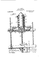
- Fig. 4 isa view similar to Fig. 3, but show ing thepipe mold, core, and their connecting mechanisms;
- Fig. 5 is a plan view taken on the line 55 of Fig.
- Fig. 6 is an enlarged detail view in section showing the friction means for holding the tainp rods in position
- Fig. 7 is a sectional view of one of the clutch mechanisms employed in my machine
- Fig. 8 is a side elevational view of the parts shown in Fig. 7.
- the numeral 1 designates any suitable motor or other source of power adapted to drive the belt passing over the pulley 3 fast with the shaft i, having the pulley or other means 5 also fast thereon over which passes the belt 6 passing under the pulley or sprocket 7 fast on the shaft 8 and over a smaller pulley or sprocket 9, fast to the shaft 10.
- the shafts l, 8 and 10, as well as the other shafts about to be mentioned, are suitably journaled in bear ings carried by the frame-work 11, supporting the other parts of the machine.
- the shaft 8 carries a driving member 12 connected by the belt 13, as indicated in dotted.
- the pipe 30 has a reciprocating motion in order to move the tJillllfil'S up and hile compressing will be now disclosed.
- rigid with the clutch"niemher 18 is a power member 31 connected by the belt to the power member 33, i igid with the shaft 34 carrying the friction.
- the frice sleeve 37, 30 by means 38 Fig. 3. represents any suitable means for moving the disk 35in and out radially of the disk 36, so as to change the speed of rotation of the sleeve 37, and therefore of the feed pipe 30. It there fore follows that the same power which to .revolve said tampers i the material,
- the sleeve 58 is lined with the packing G4, which may be of leather, and on one side it is provided with a slot 65 through which passes the spring 66 taking against the bearing plate 67 and controlled by the'wedgc 68, taking against the roller 1 69 carried by the lugs 70, rigid with said sleeve 58.
- the wedge 68 isconnccted as by i the rod 71 to the eccentric strap 72 surrounded by an eccentric 7 5, see Fig. 2, earj ried by the shaft (31.
- Said cast'in is slitted and screw-threaded at its top end and is made slightly tapered so that the screw-threadcd wheel nut. 77 may firmly bind the casting to the pipe 30. This particular connection between the casting and the pipe 3!) enables the tampers to be readily withdrawn from the mold cavity, and to he slid along the pipe 30 out of the way.
- the bell sections 7b and 79 a re placed in position, whereupon the tampcrs may be adjusted outwardly, and by hand, or if desired, new feet 57 may be placcd thereon, and the bell portion of the said pipe is thereupon thoroughly (amped.
- the core .72 may be rotated by the means new to be described, in order to give a finished smooth or glazed surface on the interior of the pipe and which may' be also lowered out of the way at the same time, so as to tend to further compress the material rather than to injure the same as would be the case if the said core .32 were raised instead oi. lowered.
- the mechanism for rotating and lowering :e core 52 is as follows, reference being had of the drawvings -lmose on the shaft 8 is a sprocket. wheel 80 coclutch member 81 on said purpose said tachable from shalt and passing over said sprocket wheel is a belt 82. indiralcd hrdotted lines in Fig. l and by full lines in Fig. 3. and
- the comb nation of a power shatt a. feed hopper and a mixing member; chain and sprocket con-.
- ncctions between said shaft and member for rotating the latter a feed pipe registering with said hopper; t'rictionally engaging connections between said shaft and. feed pipe adapted to rotate said pipe: connections comprising eccentrics carried by said shaft between said shaft and pipe adapted to reciprocate said pipe; and a tamping mocha nism adapted to be rotated and reciprocated by said pipe. substantially as described.
- a 'iower shaft a feed hopper and a mixing member; chain and sprocket conneo tions between said shaft and member for rotating the latter a feed pipe registering with said hopper; connections between said shaft and feed pipe adapted to rotate said pipe; connections between said shaft and pipe adapted to reciprocate said pipe; 9. tamping mechanism adapted to be rotated and reciprocated by said pipe; and a mold having a cavity located below and adapted to receive material from said feed pipe and in which said tamping means are adapted to operate, substantially as described.
- a mixing, means adapted to receive the mixed material from said means; mechanism for rotating said. pipe; means comprising an eccentric for re ciprocating said pipe: tamping means pro-- vided with a frictional connection with said pipe; a mold having a core associated with said tamping means; and means for con tinnonsly rotating said core after said pipe is formed, substantially as described.
- a mixing means a feed ipc adapted to receive 'the mixed material rom said means: frictional mechanism for rotatin said pipe; means comprising an eccentric for icciprocating said pipe; tainping members; an arm supporting said members and provided with a frictional connection with the same; a mold having a core associated with said tamping means: means for continuously rotating said core after said pipe is formed; means coniprisim; a screw for lowering said core out of said formed pipe; and means for controlling; the speed at which said screw lowers said core, substantially as described T.
- a pipe molding machine the coup bination of a mixing m ans; a feed pipe adapted to receive the mixed material from said means; frictional mechanism for rotating said pipe; an eccentric and lever connections for reciprocation said pipe; tamping members; oppositely disposed screw threaded arms for supporting said mcn hers; adjustable frictional onnections bctwecn. said arms and said members; a mold having a core associated with said tamping members; means for rotating said core otter said pipe is formed: means for lowcringsaid core; and means for controlling thtspe d of said core lowering means substantially as (lE'St'lll'bEtl.
- a pipe molding niacbinta the combination of a mining means; a feed pipe adapted to receive the mixed inatcriai from said means; a valve located between said pip and mixing int-ans; frictional mechanism tor rotating said pipe; an eccentric and lever connections for re iprocating said pipe; tamptng members; oppositely iii, iosed screw threaded arms for sup 'iorting said members; adjustabl frictional yonnwtions between said a rnis and said members: a mold having a core associated with said tamping members; means for rot ating said core after said pipe is formed; means for lowering said core; and m wins-for controlling the speed of said core lowering ll'ltlllS substantially as described.
- a pipe molding machine the com bination of a power shaft; a feed hopper and a mixing member; clutch and sprocket connections between said hait and member for rotating the latter; a feed pipe register in; with said hopper; a valve iocated bctween said pipe and hopper; connections between said shaft and feed pipe adapted to rotate said pipe; eminections eoinprisinga lever between said shaft and pipe adapted to reciprocate said pipe; a tamping mechanism adapted to be rotated and reciprocatcd by said pipe; oppositely disposed screw threaded arms for supporting said 'tainping n'iechanisni; ad jnstable frictional connections between said arms and said tamping mechanism, and a. mold ha ring a core associated with said lumping means, substantially as described.
- i'rirtinnal ti-irsmpingi supports for said taniping mmrhanisni rar ried by said arms: and a amid having a rvmovable rm'u assuriat'rd with said taniping i mmhanism. snhstantiaiiy as descrihad.
Landscapes
- Engineering & Computer Science (AREA)
- Mechanical Engineering (AREA)
- Manufacturing & Machinery (AREA)
- Chemical & Material Sciences (AREA)
- Ceramic Engineering (AREA)
- Manufacturing Of Tubular Articles Or Embedded Moulded Articles (AREA)
Description
A. c. :wmsou. PIPE MAKING HAGHINE. APLIUATIOI FILED APR. 5. 1911.
Patented Apr. 30, 1912.
arwy' f QM M. Z
w? M a J b V A. G; TUNXSON.
PIPE mxme MAUHINE.
LPPLIHATIOK FILED APR. 5. 1911.
1,025,035. Patented Apr. 30, 1912.
4 SHBBTSBHBET 2.
A. G. TUNISON.
PIPE MAKING MAUHINB.
@PPLIOATION Hum APR. 5 1911 Patented Apr. 30, 1912 4 BHEETS-SHBET 3.-
Patented Apr. 30, 1912.
4 SHEETS-SHEET 4.
MIN
A. C. TUNISON. PIPBMAKING MABHINE. 1 11101111011 rI'Lnn APR. 5, 1911.
l/wit new??? (9/ /aa UNITED STATES PATENT ()i' iffitl lhl.
ARTHUR C. TUNISON, OF BOISE, IDAHO, ASSIGNOR TO ATLAS CEMENT PIPE AND MACHINERY CO., OF BOISE, IDAHO, A CORPORATION OF IDAHO.
PIPE-MAKING MACHINE.
s ecification of Letters Patent.
Patented Apr. 30, 1912.
Application filed April 5, 1911. Serial No. 619,146.
To all whom it may concern Be it known that I, ARTHUR C. TUNISON, a citizen of the United States, residing at Boise, in the county of Ada and State of Idaho, have invented certain new and useful Improvements in Pipe-Making Machines; and I do hereby declare the following to be a full, clear, and exact description of the invention, such as will enable others skilled in the art to which it appertains to make and use the same.
This invention relates to means for making concrete or other plastic pipes or drains such as are employed in the construction of sewers, culverts, pipe lines and the like, and has for its object to provide a machine which will be more efficient in action, and less costly to construct, than like machines heretofore proposed.
To these ends the invention consists in a mechanism providing an even feed of the material from the hopper and ca able of distributing the same evenly in the mold beneath the tampers so that the pipe will be of a uniform density.
The invention further consists in a mech' anism comprising a plurality of tampers which can be regulated to temp the material to any desired density, and which enables the speed of manufacture to be increased. Further, the shoes employed on the tampers can be readily changed according to the thickness of the shell of the pipe it is desired to manufacture.
The invention still further consists in a mechanism comprising a core that may be revolvedwhen desired, and that may be wit drawn without injury to the pipe. This core is preferably withdrawn from the pipe in a downward direction, and therefore Wlll tend to increase the densit of the material instead of tending to in ure the pipe as would be the case if-the core should be withdrawn in an upward direction.
The invention still further consists in a machine which will manufacture various sizes of pipes, the cores of which can be speedily removed from the finished pipe no matter how densely the shell of the pipe may be tamped around the core, and the invention further consists in certain novel de tails of construction and combinations of parts more fully hereinafter disclosed and particularly pointed out in the claims.
Referring to the accompanying drawings forming a. part of this specification in which like numerals designate like parts in all the viewsz -Figure 1 is a diagrammatic pian view of a machine built in accordance with my invention With the mixing hoppers removed; Fig. 2 is a side elevational view of the parts shown in Fig. i with the mixing hoppers in place; Fig. 3 is an elcvational sectional view of a portion of the machine showing ainixing hopper and a feed pipe, together with their connecting mechanisms: Fig. 4 isa view similar to Fig. 3, but show ing thepipe mold, core, and their connecting mechanisms; Fig. 5 is a plan view taken on the line 55 of Fig. 3, of the holding and adjusting rods for thetamping mechanism, and showing the feed pipe in section; Fig. 6 is an enlarged detail view in section showing the friction means for holding the tainp rods in position; Fig. 7 is a sectional view of one of the clutch mechanisms employed in my machine; and, Fig. 8 is a side elevational view of the parts shown in Fig. 7. I
Referring first to Fig. 1 the numeral 1 designates any suitable motor or other source of power adapted to drive the belt passing over the pulley 3 fast with the shaft i, having the pulley or other means 5 also fast thereon over which passes the belt 6 passing under the pulley or sprocket 7 fast on the shaft 8 and over a smaller pulley or sprocket 9, fast to the shaft 10. The shafts l, 8 and 10, as well as the other shafts about to be mentioned, are suitably journaled in bear ings carried by the frame-work 11, supporting the other parts of the machine. The shaft 8 carries a driving member 12 connected by the belt 13, as indicated in dotted. lines, to the driving member 14 loose on the shaft 15, but adapted to be connected thereto by the clutch member to. ()n the shaft 15 is otlso mounted the clutch iii-embers 17 and 18 rigid with the latter of which is a driving member or sprocket 11 adapted to rotate the belt 20, as best illustrated in Fig. 3. The belt 20 over a sprocket 21 mounted upon the shaft 32 carrying beveled gear 23 engaging with the beveled gear 24,-rigid with the shaft 25 on which is mounted the stirring or mixing members 26 contained in the mixing hopper 27, having a delivery at 28 controlled by the hand operated valve or gate 29, registering: with the hollow feed pipe 30, as will lbw: lear fawn Fig. 3. The pipe 30 has a reciprocating motion in order to move the tJillllfil'S up and hile compressing will be now disclosed. Referring again to Fig. 1, rigid with the clutch"niemher 18 is a power member 31 connected by the belt to the power member 33, i igid with the shaft 34 carrying the friction. re the frice sleeve 37, 30 by means 38, Fig. 3. represents any suitable means for moving the disk 35in and out radially of the disk 36, so as to change the speed of rotation of the sleeve 37, and therefore of the feed pipe 30. It there fore follows that the same power which to .revolve said tampers i the material,
drives the mixing members 26 also rotates the feed pipe 30. Also mounted on the shaft 15 and rigid therewith are a plurality of eccentrics 41 having the eccentric straps 42 carrying the arms 43 and connected as by the lever 44 to the links 45, which are connected as at 46 to the sleeve 47 rigid with the feed pipe 30. The levers 44 are pivoted at 48 to the frame-work 11, and it is clear that as the shaft 15 revolves the said levers 44 will impart'to the said feed pipe 30 and tampers, the reciprocating motion above mentioned.
From the mechanism so far disclosed, it is evident that material such as cement, clay, or other suitable pipe making material, which is placed in the feed hopper 27 will be thoroughly mixed by the members 26, and will be fed down through the delivery 28 into the feed pipe 30, and through its open end 50 on to the tapered upper end 51 of the core 52, which is surrounded by the mold members 53 and 54 of the flask, as will be clear from Fig. 2. Entering the space 55, Fig. 4, between the core 52 and the flask members 53 and 54, are the tampers 56 provided with the shoes 57. The stems 56 of these tampeis pass up through a sleeve 58, Fig. 6, provided with a cross arm 59 having at one end a. sleeve (30 through which passes the splincd rod (Bl, and having at its other end a screw-threaded sleeve 62through .which passes the screwthreaded rod (33. The sleeve 58 is lined with the packing G4, which may be of leather, and on one side it is provided with a slot 65 through which passes the spring 66 taking against the bearing plate 67 and controlled by the'wedgc 68, taking against the roller 1 69 carried by the lugs 70, rigid with said sleeve 58. The wedge 68 isconnccted as by i the rod 71 to the eccentric strap 72 surrounded by an eccentric 7 5, see Fig. 2, earj ried by the shaft (31. ,i From the mechanism thus ta r described, it is evident that as the material is fed down i into the space as and the lamp rods .36 are l I t down, and it has a rotating motion in order F first 'eciprocated by the mechanism disclosed, the raid tamp rods may slide upwardly through he sleeve 58 and packing 64, so as to accommodate the increasing height of the pipe being formed. In order to increase the friction between the packing G4 and the stems 56 of the packing rods, it is only necessary to turn the rods 61 by any suitable means whereupon the wedges (58 may be forced more firmly against the spring (36, or they may be withdrawn as is desired. It is further evident that if-it is desired to increase or to decrease the radius of the pipe, it is only necessary to turn the screw rods (53 in the proper direction when the will be brought to operate in the particular circle desired. Should it be desired to increase the thickness or to decrease the thickness of the walls of the pipe, it is only necvc the feet 57 of the tampers additional feet, and for this feet 57 are made readily dethe rods 56 as by a screwthreaded joint 74. The said tampers and rods 6] and 63 are supported from the extreme lower end of the feed pipe 30 by means of a casting 75, see Fig. 3, provided with enlargements 76 through which the two rods 61 and the two rods 63 pass. Said cast'in; is slitted and screw-threaded at its top end and is made slightly tapered so that the screw-threadcd wheel nut. 77 may firmly bind the casting to the pipe 30. This particular connection between the casting and the pipe 3!) enables the tampers to be readily withdrawn from the mold cavity, and to he slid along the pipe 30 out of the way.
After the material forming the pi )0. has been filled into the cavity 55 up to tie top of the mold members 33 and 54, the bell sections 7b and 79 a re placed in position, whereupon the tampcrs may be adjusted outwardly, and by hand, or if desired, new feet 57 may be placcd thereon, and the bell portion of the said pipe is thereupon thoroughly (amped. A fter the body portion as well as the bell portion of the pipe has been thus completed, the core .72 may be rotated by the means new to be described, in order to give a finished smooth or glazed surface on the interior of the pipe and which may' be also lowered out of the way at the same time, so as to tend to further compress the material rather than to injure the same as would be the case if the said core .32 were raised instead oi. lowered.
The mechanism for rotating and lowering :e core 52 is as follows, reference being had of the drawvings -lmose on the shaft 8 is a sprocket. wheel 80 coclutch member 81 on said purpose said tachable from shalt and passing over said sprocket wheel is a belt 82. indiralcd hrdotted lines in Fig. l and by full lines in Fig. 3. and
Y n ang 1 sermvdlummwi d:
:hremi 1 110mm: H- and mm Lu downwdrd mutiun i'illff tiiikd t will in? slow uwiug in H2; Mia: iii}; shown. In n'hnr W the sprocket J! a grout dual filing may lug given to the pi slaw duwnwani motion that wii! then he inn 114911 in HM: mid 6011*. a-ta 51mm imuw hi 5, 53 and 54 :m muunled upon a grim Form 101 carrying the rollers 102, working on the tracks 103, and when the cure BL? is 10 word nutoftl1eplpe,!im said pipe 1 mi nmh'i me bars .53 and 5% nmy be rnllod um; along 1; winks HM an? ad' li e 'wu g wil ig; 11111 in? diwimrgw], at A! m and mold nmmbcrs [nu be i'awu The chm-h liifiillhQlH we may H: @i Hm gi-numi i 11k! slum in 2; i and in which a shaft is gu'mis'fell MM 1124- spiined Puma-shaped member "I M-niing between a pzsir of arms 1 flarzvingg 10mm 105 and pivoted as at pol- }m owing; to the Q in this 1mm?" L 1520 iiibil Him-Mute a h-m'ismiiimi 7 1211 =1. 9151! L ruuiily much 31;} iizui it r h simfhlc in order m n1 nulput in) 315m; :1
A m i'nait in? i are inclimref mi m; 7 bv the M1110 mm 1L1; 3 :21 0 F yim-s my a him: un 0i ihe 11 if? QM, In urder that b uir tmnnecticns mm m;- fllm'u is pi'efmatmy 7 12am! i254 the Enhancing: 2*
. gm'inm that those skified in K um marvary H10 :11 "(mgenicnt 01 Earth .1; w J Emails 01' mnstruction wilnm mm ise spirit of my im'em' in!) n win imzs timl. imiend ni' a g m "luau: illu il'auu'. any sui hi: fi
carry a strap 10!! which uh- P mnnew tiud in the (11115 11f? Hf {he Hi4 as by (In: screw bulis 111. From lim siilurfm'u now diwk fem; ihai'ypun siirling the 0.111%
lapud meui- R pa adapted in 15- ileuizmlb cmnprising a 1-. mit and pips adapted to ciprocate said pipe; and a tamping mocha nism adapted to be rotated and reciproeated by said pipe, substantially as described.
2. In a pipe molding machine, the comb nation of a power shatt; a. feed hopper and a mixing member; chain and sprocket con-.
ncctions between said shaft and member for rotating the latter: a feed pipe registering with said hopper; t'rictionally engaging connections between said shaft and. feed pipe adapted to rotate said pipe: connections comprising eccentrics carried by said shaft between said shaft and pipe adapted to reciprocate said pipe; and a tamping mocha nism adapted to be rotated and reciprocated by said pipe. substantially as described.
3. In a pipe molding machine, the combination of a 'iower shaft a feed hopper and a mixing member; chain and sprocket conneo tions between said shaft and member for rotating the latter a feed pipe registering with said hopper; connections between said shaft and feed pipe adapted to rotate said pipe; connections between said shaft and pipe adapted to reciprocate said pipe; 9. tamping mechanism adapted to be rotated and reciprocated by said pipe; and a mold having a cavity located below and adapted to receive material from said feed pipe and in which said tamping means are adapted to operate, substantially as described.
4. In a pipe molding machine. the combination of a power shaft; feed hopper and a mixing member; chain and sprocket connections between said shaft and member for rotating the latter; :1 fed pipe registering with said hopper; connections between said shaft and feed pipe adapted to rotate said pipe; eccentric and lover connections between said shaft and pipe adapted to re ciprocatcsaid pipe; a talnping mechanism adapted to be rotated and reciprocatcd by said pipe: and a mold casing and core forming a mold cavity located below adapted to receive material from said pipe and in which said tamping means are located, substantially as described.
5. In a pipe molding machine, the combination of a mixing, means; a feed pipe adapted to receive the mixed material from said means; mechanism for rotating said. pipe; means comprising an eccentric for re ciprocating said pipe: tamping means pro-- vided with a frictional connection with said pipe; a mold having a core associated with said tamping means; and means for con tinnonsly rotating said core after said pipe is formed, substantially as described.
6. In a pipe molding machine the combi nation of a mixing means; a feed ipc adapted to receive 'the mixed material rom said means: frictional mechanism for rotatin said pipe; means comprising an eccentric for icciprocating said pipe; tainping members; an arm supporting said members and provided with a frictional connection with the same; a mold having a core associated with said tamping means: means for continuously rotating said core after said pipe is formed; means coniprisim; a screw for lowering said core out of said formed pipe; and means for controlling; the speed at which said screw lowers said core, substantially as described T. In a pipe molding machine, the coup bination of a mixing m ans; a feed pipe adapted to receive the mixed material from said means; frictional mechanism for rotating said pipe; an eccentric and lever connections for reciprocation said pipe; tamping members; oppositely disposed screw threaded arms for supporting said mcn hers; adjustable frictional onnections bctwecn. said arms and said members; a mold having a core associated with said tamping members; means for rotating said core otter said pipe is formed: means for lowcringsaid core; and means for controlling thtspe d of said core lowering means substantially as (lE'St'lll'bEtl.
lo a pipe molding niacbinta the combination of a mining means; a feed pipe adapted to receive the mixed inatcriai from said means; a valve located between said pip and mixing int-ans; frictional mechanism tor rotating said pipe; an eccentric and lever connections for re iprocating said pipe; tamptng members; oppositely iii, iosed screw threaded arms for sup 'iorting said members; adjustabl frictional yonnwtions between said a rnis and said members: a mold having a core associated with said tamping members; means for rot ating said core after said pipe is formed; means for lowering said core; and m wins-for controlling the speed of said core lowering ll'ltlllS substantially as described.
9. In a pipe molding machine the com bination of a power shaft; a feed hopper and a mixing member; clutch and sprocket connections between said hait and member for rotating the latter; a feed pipe register in; with said hopper; a valve iocated bctween said pipe and hopper; connections between said shaft and feed pipe adapted to rotate said pipe; eminections eoinprisinga lever between said shaft and pipe adapted to reciprocate said pipe; a tamping mechanism adapted to be rotated and reciprocatcd by said pipe; oppositely disposed screw threaded arms for supporting said 'tainping n'iechanisni; ad jnstable frictional connections between said arms and said tamping mechanism, and a. mold ha ring a core associated with said lumping means, substantially as described.
10. In a pipe molding machine, th com bination of a power shaft; a feed hopper and a mixing member; chain and sprocket connections between said shaft and member for rotating the iatim': a feed Pilil rvgistvn iny; with said hopper: Frirtinnaliy engaging ('UltlltfliiUHH hutwovn said shaft and i'vcd pipi' adaptad t0 rutatu said pipe: itflillt'ir'iiiflllh; comprising eccvntrirs carried by said shaft i between said shaft and pipo adapti-d a; 2'0- ciprncatt: said pipv: a tainping invrhanisni adaptrd to be rotated and rui-ipruvatwi by said pipe roniprising nppnsitviy dispnsvd i screw thrvaded arms. i'rirtinnal ti-irsmpingi supports for said taniping mmrhanisni rar ried by said arms: and a amid having a rvmovable rm'u assuriat'rd with said taniping i mmhanism. snhstantiaiiy as descrihad.
1t. Tn a pipr making HHH'ilillP. the rmn- I binationof a motor: a shaft driven h said i motor: a plurality of w-ondary shafts i driven by said first namr-l shaft; a fourth 1 shai't drivvn hr war at said svrmnianv i shafts; a fifth shal't drirrn by :Hiliiiltt id i said surundar shafts; a rlnti-h rarrird In Part1 (if said :-((ll1|(i:lt' shafts: a \i-riirai shaft driven by \tilil (it said Milt-hr a mix ing in'ans'and a turd pipr rntati-d is mi 'h of said i unrth and Iitlh siial'ts: lumping: means rarriud h (:Hil Iii said pipus: a maid having a CUI'L? assuriatrd nitii vat-h ui' said talnping means; and vumwviinns [hr with l drawing said writ drivi-n h varh of said n-rlirai shai ts. substantially as desrrihed.
if. in a pipe making inarhinf'. the cumhinatinn (if a HIUiUIZ a primary shaft driven in said motor: a phiality 0E svrnndary hafts drivvn hr v aid primary shai t; a Fourth sha i't drirvn h nnv of said surnndary shai'is: a iit'lh shat't' drivvn hy another of said swnndary shafts; a (illit'il rarrifld hy t'ttl'il 01' said sue-midary shafts-1 a vertical sha lt drin-n hy ravh at said rlntrhcs: a mixing tin-ans and a 'i'rtd pipu rotated by rarh ui' aid t'mirth and tifth shafts; tainping Hitillis arrivd li rarh of said pipus: !nr ans drivvn ivy (Iitit of said fourth and iii'th sllai'ts t'nr rwiprni-ating said t'rrd piprs and t'aniping niuai si a maid ha\ in}: a wire :Lss'O' riatt-d with (:ilil at said tainping means; and minim-[inn t'nr withdrawing said (-nres drirr-n in inn-h ni' aid \t-rtirai shafts, suhstantiaii) as dhs rihrd.
ARTHUR TUNIHUN.
'itnv v
Applications Claiming Priority (1)
| Application Number | Priority Date | Filing Date | Title |
|---|---|---|---|
| US1025035TA |
Publications (1)
| Publication Number | Publication Date |
|---|---|
| US1025035A true US1025035A (en) | 1912-04-30 |
Family
ID=3093331
Family Applications (1)
| Application Number | Title | Priority Date | Filing Date |
|---|---|---|---|
| US00000000A Expired - Lifetime US1025035A (en) | Pipe making machine. |
Country Status (1)
| Country | Link |
|---|---|
| US (1) | US1025035A (en) |
-
0
- US US00000000A patent/US1025035A/en not_active Expired - Lifetime
Similar Documents
| Publication | Publication Date | Title |
|---|---|---|
| US3159897A (en) | Machine for extruding hollow cored concrete sections | |
| CN113001739A (en) | Device for processing concrete precast block | |
| US1895740A (en) | Method of making concrete pipe | |
| US1025035A (en) | Pipe making machine. | |
| US3141222A (en) | Concrete pipe making apparatus | |
| US2870513A (en) | Pipe making apparatus | |
| US2786252A (en) | Apparatus for forming dense coating on pipe | |
| AU2003258744B2 (en) | Method and apparatus for fabricating a hollow-core concrete product | |
| US2404464A (en) | Pipe forming machine | |
| DE623264C (en) | Machine for the production of pipes from cementitious material or for lining pipes with this material | |
| US2231064A (en) | Machine for molding cementitious block | |
| US1534768A (en) | Brick machine | |
| US1558030A (en) | Molding apparatus for the manufacture of tubular earthenware or stoneware articles | |
| US462087A (en) | sherman | |
| US115030A (en) | Improvement in machines for molding drain and sewer pipes | |
| US1428044A (en) | Concrete-pipe machine | |
| US565291A (en) | Brick machine | |
| US250883A (en) | James william butler | |
| DE589373C (en) | Casting machine for the production of ceramic vessels | |
| US2163118A (en) | Apparatus for making hollow bodies of plastic material | |
| US3161935A (en) | Tamping mechanism | |
| US1048689A (en) | Molding-machine. | |
| US1400457A (en) | Machine for making reinforced-concrete pipe | |
| US1159515A (en) | Tile-making machine. | |
| US20160236374A1 (en) | Packerhead machine |