US1024953A - Combined tie and rail-fastener. - Google Patents
Combined tie and rail-fastener. Download PDFInfo
- Publication number
- US1024953A US1024953A US64476111A US1911644761A US1024953A US 1024953 A US1024953 A US 1024953A US 64476111 A US64476111 A US 64476111A US 1911644761 A US1911644761 A US 1911644761A US 1024953 A US1024953 A US 1024953A
- Authority
- US
- United States
- Prior art keywords
- rail
- fastener
- tie
- combined tie
- bolts
- Prior art date
- Legal status (The legal status is an assumption and is not a legal conclusion. Google has not performed a legal analysis and makes no representation as to the accuracy of the status listed.)
- Expired - Lifetime
Links
- 238000004873 anchoring Methods 0.000 description 4
- 238000010276 construction Methods 0.000 description 2
- 238000006073 displacement reaction Methods 0.000 description 2
- 241000283986 Lepus Species 0.000 description 1
- 230000006978 adaptation Effects 0.000 description 1
- 238000004519 manufacturing process Methods 0.000 description 1
- 230000004048 modification Effects 0.000 description 1
- 238000012986 modification Methods 0.000 description 1
Images
Classifications
-
- E—FIXED CONSTRUCTIONS
- E01—CONSTRUCTION OF ROADS, RAILWAYS, OR BRIDGES
- E01B—PERMANENT WAY; PERMANENT-WAY TOOLS; MACHINES FOR MAKING RAILWAYS OF ALL KINDS
- E01B9/00—Fastening rails on sleepers, or the like
- E01B9/02—Fastening rails, tie-plates, or chairs directly on sleepers or foundations; Means therefor
- E01B9/04—Fastening on wooden or concrete sleepers or on masonry without clamp members
- E01B9/10—Screws or bolts for sleepers
Definitions
- This invention relates -to a combined tie and rail fastener, and has for its object to provide, in a manner as hereinafter set forth, a combined tie and rail fastener for not only supporting a track rail, but also for securing the track rail to the tie in a manner to prevent lateral and longitudinal displacement of the track rail.
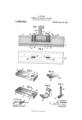
- FIG. 1 is a longitudinal sectional view, broken away, of a combined tie and rail fastener in accordance .with this invention, and further showing the adaptation thereof in connection with a track rail.
- Fig. 2 is a top plan view of the tie broken away.
- Fig. 3 is a perspective view of an anchoring plate forming an element of the fastener.
- Fig. d is a perspective view of the anchoring plate looking at the lower side thereof.
- Fig. 5 is a perspective of one of the rail fasteners.
- Fig. 6 is a perspective of the other rail fastener, and
- Fig. 7 is a perspective view broken away of one of the retaining bolts for a rail fastener.
- acter 1 is constructed of concrete and reinforced by longitudinal extending cylindrical bars 2, disposed throughout the body thereof.
- the reference character 3, 4L denote a pair of vertically disposed openings formed in the upper face of the tie 1, and which communicate at the lower ends with a longitudinally extending pocket 5.
- a lo-ngitudinally extending anchoring plate 6 having its lower face cut away to provide a recess 7.
- lIhe plate 6 near each end is formed with a vertically disposed retangailar opening communicating with the recess 7.
- the openings in the plate 6 are indicated 8, 9.
- the upper .wall 10 of the recess 7 at each end thereof is formed with a. pair of notches.
- the notches at one end are indicated at 11, and communicate with the openings 8.
- the notches at the other end are indicated at 12, and communicate with the opening 9.
- a track rail 13 which is secured in position by a pair of rail fasteners indicated at 14C, 15.
- the fastener 14 is formed with (at its inner end) an inwardly extending lip 16a, adapted to overlap one side of the base of the rail 18.
- the fastener 15 has projecting from its inner end an inwardly extending and upwardly disposed brace 16D which overlaps the other side of the base of the rail 13 and also engages the web and head of said rail.
- the lip 16a and brace 16b secure the rail to the tie so as to prevent lateral and longitudinal displacement.
- the rail fasteners 14, 15 are secured in position by T-bolts 16, which extend down through the openings 3, 4C and 8, 9, and are then given a half turn so that the heads 17, thereof will engage in t-he notches 11 and 12, the top walls of the notches constituting stops for arresting upward movements of the bolts.
- T-bolts 16 which extend down through the openings 3, 4C and 8, 9, and are then given a half turn so that the heads 17, thereof will engage in t-he notches 11 and 12, the top walls of the notches constituting stops for arresting upward movements of the bolts.
- a tie provided near each end with a longitudinally extending pocket 5 and a pair of vertically disposed openings communicating with said pocket inwardly of the ends thereof, an anchoring plate mounted in and conforming to the contour of said pocket and provided near each end with a longitudinally extending opening registering with a vertical opening, said plate having its lower face provided with a rectangular pocket, the upper Wall of said recess at each end being provided with a transverse notch intersecting a rectangular opening and extending in a plane central of the length of the said opening, said notches providing seats, T-bolts extending up through said registering openings and having their heads engaging said seat to prevent Withdrawal of the bolts, rail fastening devices mounted upon said tie inclosing said vert-ical openings and extended to engage the hase of a rail for maintaining it in position, said bolts extending through said fasteners, and means mounted upon the pro jeoting ends of the bolts for securing the fasteners in position.
Landscapes
- Engineering & Computer Science (AREA)
- Mechanical Engineering (AREA)
- Architecture (AREA)
- Civil Engineering (AREA)
- Structural Engineering (AREA)
- Joining Of Building Structures In Genera (AREA)
Description
E; STACK. COMBINED TIE AND RAIL PASTBNBR. APPLICATION PILVEDAUG. 18, 1911.
WITNESSES; Y l
v 16M @PJM COLUMBIA PLANOGRAPH C0.. WASHINGTON. D. C.
, vUNITED STATES PATENT OFFICE EDWARD STACK, OF PITTSBURGH, PENNSYLVANIA.
COMBINED TIE AND RAID-FASTENER.
To all whom t may concern:
Be it known that I, EDWARD STACK, citi- Zen of the United States of America, residing at Pittsburgh, in the county of Allegheny and State of Pennsylvania, have invented certain new and useful Improvements in Combined Ties and Rail-Fasteners, of ywhich the following is a specification, reference being had therein to the accompanying draw- This invention relates -to a combined tie and rail fastener, and has for its object to provide, in a manner as hereinafter set forth, a combined tie and rail fastener for not only supporting a track rail, but also for securing the track rail to the tie in a manner to prevent lateral and longitudinal displacement of the track rail.
Further objects of the invention are to provide a combined tie and rail fastener which is simple in its construction and arrangement, strong, durable, eiilcient in its use, conveniently set up with respect to the track rail, and comparatively inexpensive to manufacture.
IVith the foregoing, and other objects in view, the invention consists in t-he novel construction, combination and arrangement of parts as hereinafter more specifically described, and illustrated in the accompanying drawings, but it is to be understood that changes, varia-tions and modifications can be resorted to, which fall within the scope of the claim hereunto appended.
In describing the invention in detail, reference is had to the accompanying drawings, wherein like reference characters denote corresponding parts throughout the several views, and in which- Figure 1 is a longitudinal sectional view, broken away, of a combined tie and rail fastener in accordance .with this invention, and further showing the adaptation thereof in connection with a track rail. Fig. 2 is a top plan view of the tie broken away. Fig. 3 is a perspective view of an anchoring plate forming an element of the fastener. Fig. d is a perspective view of the anchoring plate looking at the lower side thereof. Fig. 5 is a perspective of one of the rail fasteners. Fig. 6 is a perspective of the other rail fastener, and Fig. 7 is a perspective view broken away of one of the retaining bolts for a rail fastener.
Referring to the drawings in detail, the tie which is indicated by the reference char- Speccation of Letters Patent.'-
Applcaton filed August 18, 1911.
Patented Apr. 30, 1912.
Serial No. 644,761.
acter 1, is constructed of concrete and reinforced by longitudinal extending cylindrical bars 2, disposed throughout the body thereof.
The reference character 3, 4L denote a pair of vertically disposed openings formed in the upper face of the tie 1, and which communicate at the lower ends with a longitudinally extending pocket 5.
Mounted in the pocket 5, is a lo-ngitudinally extending anchoring plate 6, having its lower face cut away to provide a recess 7. lIhe plate 6 near each end is formed with a vertically disposed retangailar opening communicating with the recess 7. The openings in the plate 6 are indicated 8, 9. The upper .wall 10 of the recess 7 at each end thereof is formed with a. pair of notches. The notches at one end are indicated at 11, and communicate with the openings 8. The notches at the other end are indicated at 12, and communicate with the opening 9.
Mounted upon tie 1 is a track rail 13, which is secured in position by a pair of rail fasteners indicated at 14C, 15. The fastener 14 is formed with (at its inner end) an inwardly extending lip 16a, adapted to overlap one side of the base of the rail 18. The fastener 15 has projecting from its inner end an inwardly extending and upwardly disposed brace 16D which overlaps the other side of the base of the rail 13 and also engages the web and head of said rail. The lip 16a and brace 16b secure the rail to the tie so as to prevent lateral and longitudinal displacement.
The rail fasteners 14, 15 are secured in position by T-bolts 16, which extend down through the openings 3, 4C and 8, 9, and are then given a half turn so that the heads 17, thereof will engage in t-he notches 11 and 12, the top walls of the notches constituting stops for arresting upward movements of the bolts. Mounted upon the upper end of the bolts 16, said ends projecting above the rail fasteners and threaded, are nuts 18,
which when they are secured against the rail fasteners and in connection with the heads of the bolt-s maintain the track rail in position.
What I claim is In combination, a tie provided near each end with a longitudinally extending pocket 5 and a pair of vertically disposed openings communicating with said pocket inwardly of the ends thereof, an anchoring plate mounted in and conforming to the contour of said pocket and provided near each end with a longitudinally extending opening registering with a vertical opening, said plate having its lower face provided with a rectangular pocket, the upper Wall of said recess at each end being provided with a transverse notch intersecting a rectangular opening and extending in a plane central of the length of the said opening, said notches providing seats, T-bolts extending up through said registering openings and having their heads engaging said seat to prevent Withdrawal of the bolts, rail fastening devices mounted upon said tie inclosing said vert-ical openings and extended to engage the hase of a rail for maintaining it in position, said bolts extending through said fasteners, and means mounted upon the pro jeoting ends of the bolts for securing the fasteners in position.
In testimony whereof I atiX my signaf ture in the presence of two Witnesses.
EDWARD STACK.
Copies of this patent may be obtained for five cents each, by addressing the Commissioner of Patents, Washington, I). C.
Priority Applications (1)
| Application Number | Priority Date | Filing Date | Title |
|---|---|---|---|
| US64476111A US1024953A (en) | 1911-08-18 | 1911-08-18 | Combined tie and rail-fastener. |
Applications Claiming Priority (1)
| Application Number | Priority Date | Filing Date | Title |
|---|---|---|---|
| US64476111A US1024953A (en) | 1911-08-18 | 1911-08-18 | Combined tie and rail-fastener. |
Publications (1)
| Publication Number | Publication Date |
|---|---|
| US1024953A true US1024953A (en) | 1912-04-30 |
Family
ID=3093249
Family Applications (1)
| Application Number | Title | Priority Date | Filing Date |
|---|---|---|---|
| US64476111A Expired - Lifetime US1024953A (en) | 1911-08-18 | 1911-08-18 | Combined tie and rail-fastener. |
Country Status (1)
| Country | Link |
|---|---|
| US (1) | US1024953A (en) |
-
1911
- 1911-08-18 US US64476111A patent/US1024953A/en not_active Expired - Lifetime
Similar Documents
| Publication | Publication Date | Title |
|---|---|---|
| US1209477A (en) | Railroad-tie. | |
| US1065595A (en) | Rail-holding device. | |
| US1091088A (en) | Metallic railway-tie. | |
| US1184627A (en) | Railroad-tie. | |
| US1027232A (en) | Tie and rail-fastener. | |
| US1152417A (en) | Railway-tie. | |
| US1070103A (en) | Rail-tie. | |
| US1030896A (en) | Tie and rail-fastener. | |
| US1006208A (en) | Metallic cross-tie and rail-fastener. | |
| US562974A (en) | Railroad-tie | |
| US1028587A (en) | Tie and rail-fastener. | |
| US410236A (en) | Railway-tie | |
| US1198145A (en) | Railway-tie. | |
| US1029628A (en) | Railroad-tie. | |
| US873294A (en) | Railway-tie. | |
| US656799A (en) | Metallic cross-tie and rail-fastening. | |
| US1029376A (en) | Tie and rail-fastener. | |
| US792134A (en) | Railway-tie. | |
| US770690A (en) | Railway-tie | |
| US1088802A (en) | Railway-tie. | |
| US880381A (en) | Metal rail-tie. | |
| US370072A (en) | Railway-tie | |
| US684758A (en) | Railway-tie. | |
| US874556A (en) | Metal railway-tie. | |
| US979785A (en) | Railway-tie. |