US10240328B1 - Dual provision shower head - Google Patents
Dual provision shower head Download PDFInfo
- Publication number
- US10240328B1 US10240328B1 US15/702,756 US201715702756A US10240328B1 US 10240328 B1 US10240328 B1 US 10240328B1 US 201715702756 A US201715702756 A US 201715702756A US 10240328 B1 US10240328 B1 US 10240328B1
- Authority
- US
- United States
- Prior art keywords
- shower head
- chamber
- water
- sector
- soap
- Prior art date
- Legal status (The legal status is an assumption and is not a legal conclusion. Google has not performed a legal analysis and makes no representation as to the accuracy of the status listed.)
- Active, expires
Links
Images


Classifications
-
- E—FIXED CONSTRUCTIONS
- E03—WATER SUPPLY; SEWERAGE
- E03C—DOMESTIC PLUMBING INSTALLATIONS FOR FRESH WATER OR WASTE WATER; SINKS
- E03C1/00—Domestic plumbing installations for fresh water or waste water; Sinks
- E03C1/02—Plumbing installations for fresh water
- E03C1/04—Water-basin installations specially adapted to wash-basins or baths
- E03C1/046—Adding soap, disinfectant, or the like in the supply line or at the water outlet
-
- B—PERFORMING OPERATIONS; TRANSPORTING
- B05—SPRAYING OR ATOMISING IN GENERAL; APPLYING FLUENT MATERIALS TO SURFACES, IN GENERAL
- B05B—SPRAYING APPARATUS; ATOMISING APPARATUS; NOZZLES
- B05B7/00—Spraying apparatus for discharge of liquids or other fluent materials from two or more sources, e.g. of liquid and air, of powder and gas
- B05B7/24—Spraying apparatus for discharge of liquids or other fluent materials from two or more sources, e.g. of liquid and air, of powder and gas with means, e.g. a container, for supplying liquid or other fluent material to a discharge device
- B05B7/2402—Apparatus to be carried on or by a person, e.g. by hand; Apparatus comprising containers fixed to the discharge device
- B05B7/2462—Apparatus to be carried on or by a person, e.g. by hand; Apparatus comprising containers fixed to the discharge device using a carrying liquid flowing through the container for dissolving a block of solid material
-
- E—FIXED CONSTRUCTIONS
- E03—WATER SUPPLY; SEWERAGE
- E03C—DOMESTIC PLUMBING INSTALLATIONS FOR FRESH WATER OR WASTE WATER; SINKS
- E03C1/00—Domestic plumbing installations for fresh water or waste water; Sinks
- E03C1/02—Plumbing installations for fresh water
- E03C1/04—Water-basin installations specially adapted to wash-basins or baths
- E03C1/0408—Water installations especially for showers
- E03C1/0409—Shower handles
-
- B—PERFORMING OPERATIONS; TRANSPORTING
- B05—SPRAYING OR ATOMISING IN GENERAL; APPLYING FLUENT MATERIALS TO SURFACES, IN GENERAL
- B05B—SPRAYING APPARATUS; ATOMISING APPARATUS; NOZZLES
- B05B1/00—Nozzles, spray heads or other outlets, with or without auxiliary devices such as valves, heating means
- B05B1/14—Nozzles, spray heads or other outlets, with or without auxiliary devices such as valves, heating means with multiple outlet openings; with strainers in or outside the outlet opening
- B05B1/18—Roses; Shower heads
Definitions
- the present invention relates to a shower head that delivers both water and soap through the shower stream.
- shower heads are predominantly known for dispensing streaming water to the one that is showering for hygiene purposes to promote hygienic behavior patterns.
- shower heads can play a major role, hygienically, for the one that is showering.
- the shower head serves as an effective instrument geared toward the promotion of good health.
- the functions, designs, and accessibilities of shower heads have evolved from the many innovations of the original invention.
- the invention of the shower head has made its advances toward improving its quality in function, design, and accessibility, the sole purpose has remained consistent throughout many years of its existence.
- the sole purpose of the shower head has been to dispense water to the one that is showering for desired usage.
- a shower head comprising a spigot having threads for the assembly of a shower hose and having an entrance point and hollow structure for the passage of a water stream, a shower head handle having a spigot connected to the inferior position of the handle, an internally embedded soap dispenser having a chamber that is positioned in the internal structure of the shower head, a head connection leading from the superior position of the shower head handle, opposite of the end of the shower head handle where the spigot is connected, and a pattern plate having one or more pattern hole(s).
- the shower head handle is divided into two or more sectors enabling the shower head handle to furthermore expose the internally embedded soap dispenser chamber.
- a source of a seal located between the divided sectors, of the shower head handle, allowing the shower head handle to be tightly sealed when the sectors of the shower head handle are connected.
- a source of a hinge built on or into the shower head handle wherein the hinge enables the divided sectors of the shower head handle to open and close without completely detaching while being held together by the hinge.
- the integrated latch of the shower head handle enables the disengagement and reconnection of the divided sectors of the shower head handle.
- the hinge of the shower head handle enables the divided sectors of the shower head handle to open and close without completely detaching while being held together by the hinge.
- the latch slot and the latch glide groove(s) direct and enable movement of the latch when the latch is ascending or descending along the shower head handle when the sectors of the shower head handle are in the process of being sealed or detached.
- the internally embedded soap dispenser chamber is built into or connected to the internal structure of the shower head handle of the shower head.
- valve(s) wherein the water stream of the shower head may emerge and travel through the shower head and the internally embedded soap dispenser chamber.
- a further source of a container, a brim, and a base where the dispensing products placed in the internally embedded soap dispenser chamber may be contained.
- the pattern hole(s) compatibly enable the delivery of the melded substances, that may be, created in the internally embedded soap dispenser chamber.
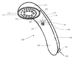
- FIG. 1 is an elevation and perspective view of a closed shower head according to an embodiment of the present invention.
- FIG. 2 is a rear fragmentary elevation view of FIG. 1 viewed along the section line 2 - 2 in FIG. 1 according to an embodiment of the present invention.
- FIG. 3 is a side perspective view of a shower head open according to an embodiment of the present invention of FIG. 1 .
- FIG. 4 is a cross-sectional view of FIG. 3 viewed along the section line 4 - 4 in FIG. 3 , depicting the motion and direction of water and soap of an embodiment of the present invention.
- FIG. 5 is a top plan overhead view of FIG. 4 , depicting an interior layout of an embodiment of the present invention.
- FIG. 6 is an elevation view of a shower head according to a further embodiment of the present invention.
- FIG. 7 is a top plan overhead view of an interior layout of an embodiment of the present invention according to a further embodiment of the present invention.
- the inventor provides a shower head in a preferred embodiment that imitates a handheld shower head that, in this example, utilizes the mechanism of a dual operation system of an embedded soap dispenser and water stream function of a shower head.
- the present invention is described in enabling detail in the following examples, which may represent more than one embodiment of the present invention.
- FIG. 1 is an elevation and perspective view of a closed shower head 100 according to an embodiment of the present invention.
- shower head 100 is adapted to imitate a handheld shower head.
- the example should not be interpreted as a limitation of the present invention.
- Other depictions for shower head 100 are possible and may also be considered according to one or more embodiments of the present invention.
- the inventor chooses to use the depiction of a handheld shower head in a preferred embodiment because of the mechanisms involved with the present invention.
- a rain shower head, dual shower head, any other type of shower head or faucet may be imitated without deserting from the overall scope of the present invention.
- the shower head 100 may include a spigot 101 accompanied with threads.
- the spigot 101 has a spigot entrance 110 to the hollow internal component of the spigot 101 for water passage.
- shower head 100 may include an obverse inferior handle section 102 and a posterior inferior handle section 103 for an inferior grip of the shower head 100 .
- the shower head 100 may include a sliding latch 104 , a latch slot 109 , a latch glide groove 108 , a obverse seal 105 , and a posterior seal 107 .
- the sliding latch 104 is directed upward 106 on the latch glide groove 108 and the latch slot 109 , in a mechanism involved to cause the obverse seal 105 and posterior seal 107 to be released so that the handle of the shower head 100 could be opened at a given position of the handle.
- the shower head 100 may include an obverse superior handle section 114 and a posterior superior handle section 115 for a superior grip of the shower head 100 .
- the shower head 100 may include a head connection 113 to an end of the posterior superior handle section 115 .
- the head connection 113 of the shower head 100 may include a shower head adjuster ring 116 , a pattern plate 112 , and one or more pattern hole(s) 111 .
- the inventor chooses to more than one pattern hole.
- the shower head adjuster ring 116 may be interchangeable to where the preference in pattern holes 111 can be adjusted for desired usage.
- the pattern plate 112 in this example lodges the pattern holes 111 .
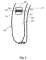
- FIG. 2 is a rear fragmentary elevation view of FIG. 1 viewed along the section line 2 - 2 in FIG. 1 according to an embodiment of the present invention.
- the shower head 100 may be modified to imitate a handheld shower head that may be accompanied by two hinge leaves 206 therein attached to a leaf connection piece 201 , to hinge knuckles 202 and hinge bearings 205 .
- This example of the embodiment of the present invention is not to be interpreted as a limitation of the present invention.
- Other depictions of attachable instruments may also be considered according to one or more embodiments of the present invention without deserting from the overall scope of the present invention.
- the inventor chooses to use the depiction of a hinge attached to the shower head 100 , in a preferred embodiment because of the mechanism involved with the present invention.
- the posterior superior handle section 115 and posterior inferior handle section 103 may be each attached to a hinge leaf 206 .
- the hinge leaf 206 contains screws 207 .
- the hinge leaf 206 has a leaf connection piece 201 that links the hinge leaf 206 to hinge knuckles 202 and hinge bearings 205 .
- there is a pin tip 204 which is used to hold the hinge knuckles 202 and hinge bearings 205 in place.
- the mechanism facilitated for the shower head 100 viewed in FIG. 2 may be, upon the shower head 100 being released to be opened, the posterior seal 107 is released and slightly disjointed. Once the posterior seal 107 is slightly disjointed the hinge knuckles 202 and the hinge bearings 205 rotate in opposite directions of one another to completely open the disjointed shower head 100 .
- the leaf connection piece 201 that attach to the hinge knuckles 202 and hinge bearings 205 assure that the superior section 115 and inferior section 103 of the shower head 100 do not completely detach from one another, which would cause the shower head 100 to be divided into two ununified sections.
- the screws 207 may be fastened to the hinge leaf 206 to secure the hinge leaf 206 on the posterior superior handle section 115 and the posterior inferior handle section 103 to prevent the hinge leaf 206 from eluding from the posterior superior handle section 115 and the posterior inferior handle section 103 .
- FIG. 3 is a side perspective view of a shower head 300 open according to an embodiment of the present invention of FIG. 1 .
- the mechanism facilitated for shower head 300 may be, when the sliding latch 104 is released from the sliding glide grooves 108 , the hinge knuckles 202 and hinge bearings 205 rotate in opposite directions of one another, then the shower head's 300 internal structure will be made visible.
- the internal structure is divided into two sectors, a superior internal sector 301 and an inferior internal sector 302 .
- FIG. 4 is a cross-sectional view of FIG. 3 viewed along the section line 4 - 4 in FIG. 3 , depicting the motion and direction of water 405 and soap 402 of an embodiment of the present invention.
- shower head 300 may have a spigot entrance 110 to the spigot 101 where the water 405 passes through to the shower head 300 .
- shower head 300 may have one or more inferior internal valve(s) 401 and one or more superior internal valve(s) 403 . In this example of the present invention the inventor chooses to depict more than one inferior internal valve 401 and superior internal valve 403 .
- the mechanism facilitated for the shower head 300 may be, once the water 405 passes through the spigot 101 , the water 405 makes way to the inferior internal valves 401 and the superior internal valves 403 .
- the water 405 protrudes through the inferior internal valves 401 , it merges with the deposited soap 402 in the shower head 300 .
- the water 405 and soap 402 form a new liquid combination 404 which consist of the combination of water 405 and soap 402 .
- the water 405 from the superior internal valves 403 further assist with passage of the stream of the new liquid combination 404 throughout the shower head 300 .
- FIG. 5 is a top plan overhead view of FIG. 4 , depicting an interior layout of an embodiment of the present invention.
- interior layout of the internally embedded soap dispenser 500 is visible.
- the internally embedded soap dispenser 500 may be where the soap deposit is contained to be combined with the water stream to be dispensed.
- the internally embedded soap dispenser 500 may have a base 501 and one or more inferior internal valves 401 which may be located at the base 501 .
- the internally embedded soap dispenser 500 may also have a brim 505 and one or more superior internal valves 403 which may be located along the brim 505 .
- the internally embedded soap dispenser 500 may have walls surrounding the base 501 and supporting the brim 505 of the container.
- these walls may be an obverse wall 502 , later walls 503 , and a posterior wall 504 .
- these walls assist in containing the deposited soap dispensed in the internally embedded soap dispenser 500 .
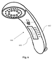
- FIG. 6 is an elevation view of a shower head 100 according to a further embodiment of the present invention.
- the shower head 100 further includes a feature that simulates a viewing window 601 and indicia 602 .
- other simulations may be employed in order to simulate a viewing window 601 and indicia 602 .
- the indicia 602 is used to measure units of time and the viewing window 601 works as a correspondent to the indicia 602 , so that the quantity of soap that is dispensed in the present invention may correlate to the desired quantity of time decided based upon the indicia 602 units.
- other simulations may have the indicia 602 in consistent increments of five minutes, fifteen minutes, or thirty minutes.
- the further embodiment is not to be interpreted as a limitation of the further embodiment of the present invention.
- FIG. 7 is a top plan overhead view of an interior layout of an embodiment of the present invention according to a further embodiment of the present invention.
- the internally embedded soap dispenser 500 further includes a viewing window 601 and obverse walls 701 with obverse adjacent walls 702 .
- Other replications may also be adopted in other embodiments of the present invention. This example is not to place any limitations on the further embodiment of the present invention.
Landscapes
- Health & Medical Sciences (AREA)
- Life Sciences & Earth Sciences (AREA)
- Engineering & Computer Science (AREA)
- Hydrology & Water Resources (AREA)
- Public Health (AREA)
- Water Supply & Treatment (AREA)
- Bathtubs, Showers, And Their Attachments (AREA)
Abstract
Description
Claims (7)
Priority Applications (2)
| Application Number | Priority Date | Filing Date | Title |
|---|---|---|---|
| US15/702,756 US10240328B1 (en) | 2017-09-12 | 2017-09-12 | Dual provision shower head |
| PCT/US2018/049294 WO2019055239A1 (en) | 2017-09-12 | 2018-09-03 | Dual provision shower head |
Applications Claiming Priority (1)
| Application Number | Priority Date | Filing Date | Title |
|---|---|---|---|
| US15/702,756 US10240328B1 (en) | 2017-09-12 | 2017-09-12 | Dual provision shower head |
Publications (2)
| Publication Number | Publication Date |
|---|---|
| US20190078306A1 US20190078306A1 (en) | 2019-03-14 |
| US10240328B1 true US10240328B1 (en) | 2019-03-26 |
Family
ID=65630691
Family Applications (1)
| Application Number | Title | Priority Date | Filing Date |
|---|---|---|---|
| US15/702,756 Active 2037-09-13 US10240328B1 (en) | 2017-09-12 | 2017-09-12 | Dual provision shower head |
Country Status (2)
| Country | Link |
|---|---|
| US (1) | US10240328B1 (en) |
| WO (1) | WO2019055239A1 (en) |
Cited By (2)
| Publication number | Priority date | Publication date | Assignee | Title |
|---|---|---|---|---|
| US10562044B2 (en) * | 2013-07-03 | 2020-02-18 | Steve SUNSHINE | Shower head assembly |
| US12337388B2 (en) * | 2023-02-15 | 2025-06-24 | Agnitron Technology, Inc. | Metal 3D printed heat exchangers and fluid directing devices |
Families Citing this family (4)
| Publication number | Priority date | Publication date | Assignee | Title |
|---|---|---|---|---|
| CN111877467B (en) * | 2020-09-02 | 2025-07-08 | 杨钟雄 | Central waterway component, bathing system and control method of central waterway component |
| US11761183B2 (en) | 2021-05-18 | 2023-09-19 | Jose Mesarina | Soap dispenser shower head apparatus |
| RU2770491C1 (en) * | 2021-05-20 | 2022-04-18 | Арслан Ималуевич Джавтаев | Shower head in piston and spring-piston versions of liquid detergent supply |
| US20240295101A1 (en) * | 2023-03-02 | 2024-09-05 | Tetia T. Jomah | Lather Shower Head |
Citations (87)
| Publication number | Priority date | Publication date | Assignee | Title |
|---|---|---|---|---|
| US1117634A (en) * | 1912-05-17 | 1914-11-17 | Thomas Bowes | Soap-holder. |
| US1217597A (en) * | 1917-01-12 | 1917-02-27 | Josef Hecht | Fountain-brush. |
| US1342994A (en) * | 1920-03-11 | 1920-06-08 | Fitzgerald Mfg Co | Bath-spray |
| US1478392A (en) * | 1922-12-20 | 1923-12-25 | Dennis B Kearney | Combined detergent receptacle and brush |
| US1521111A (en) * | 1923-01-22 | 1924-12-30 | Bree Ida La | Bath brush |
| US1668802A (en) * | 1925-04-13 | 1928-05-08 | Frank J Cantrell | Plumbing fixture |
| US1679561A (en) * | 1924-04-26 | 1928-08-07 | Frank J Cantrell | Plumbing fixture |
| US1751524A (en) * | 1929-02-01 | 1930-03-25 | Harold J Moss | Shower-nozzle attachment |
| US2019705A (en) * | 1931-10-15 | 1935-11-05 | Gyro Brush Co | Household appliance |
| US2603805A (en) * | 1949-07-26 | 1952-07-22 | Raymond B Maestas | Fountain brush |
| US2659627A (en) * | 1952-05-22 | 1953-11-17 | Manuel L Avila | Shower head |
| US2739328A (en) * | 1955-01-12 | 1956-03-27 | Dorothy K Bernier | Soap brush |
| US2986340A (en) * | 1959-05-04 | 1961-05-30 | Ernest C Webb | Device for supporting and positioning a water conditioning pellet |
| US3070316A (en) * | 1961-06-16 | 1962-12-25 | Miville Edouard | Soap and water mixing valve |
| US3194444A (en) * | 1964-10-30 | 1965-07-13 | Hubert George | Dispenser for entraining an additive into a stream of water |
| US3231200A (en) * | 1963-08-05 | 1966-01-25 | Sam Heald Co | Shower head and liquid soap dispensing and metering means |
| US3581998A (en) * | 1970-07-29 | 1971-06-01 | Maurice F Roche | Soap dispensing means |
| US3589819A (en) * | 1969-06-02 | 1971-06-29 | Clifford F Bryant | Car-washing aid |
| US3610535A (en) * | 1969-09-03 | 1971-10-05 | Mite Corp | Liquids mixing and selective delivery system |
| US3628732A (en) * | 1970-03-19 | 1971-12-21 | Vincent Vicari | Soap mixer and dispenser for shower baths and the like |
| US3763888A (en) * | 1972-04-26 | 1973-10-09 | W Duecker | Aspirating valve |
| US3764074A (en) * | 1972-01-20 | 1973-10-09 | D James | Shower head and liquid agent dispensing attachment |
| US3891149A (en) * | 1972-01-05 | 1975-06-24 | Louis Rendemonti | Method and apparatus for simultaneously deodorizing and disinfecting the interiors of vehicles |
| US3944140A (en) * | 1975-03-24 | 1976-03-16 | Lawrence Peska Associates, Inc. | Shower head |
| US4171169A (en) * | 1978-01-03 | 1979-10-16 | Williams Stanley B | Hand held washer |
| US4193520A (en) * | 1977-08-31 | 1980-03-18 | Robert Duffield | Device for adding soap to shower water |
| US4218013A (en) * | 1978-08-11 | 1980-08-19 | Davison Charles A | Shower head fluid dispenser |
| US4236840A (en) * | 1979-02-05 | 1980-12-02 | Kennedy Michael D | Internal reservoired soap dispensing animal washer |
| US4322036A (en) * | 1980-02-13 | 1982-03-30 | Bly Herbert A | Device for dispensing and dispersing liquid additives in shower bath water |
| US4366840A (en) * | 1980-05-05 | 1983-01-04 | Mckane Jr Thomas D | Fluid injector spray device |
| US4609149A (en) * | 1983-08-01 | 1986-09-02 | Thomas Jessen | Injection gun system for lawn treatment |
| US4623095A (en) * | 1984-11-19 | 1986-11-18 | Pronk Frank E | Liquid adding apparatus and method for a shower fixture |
| US4933080A (en) * | 1989-01-13 | 1990-06-12 | Associated Mills Inc. | Housing with replaceable filter cartridge for use with shower head |
| US4998836A (en) * | 1989-04-25 | 1991-03-12 | Mark Scripnick | Venturi line operated soap brush |
| USD326896S (en) * | 1990-08-09 | 1992-06-09 | Mcneely John M | Combined shower head and moisturizer dispenser |
| US5174503A (en) * | 1991-06-24 | 1992-12-29 | Gasaway Douglas W | Shower mounted plural liquids dispenser |
| US5192427A (en) * | 1990-05-24 | 1993-03-09 | Douglas R. Eger | Shower filters and accessories |
| US5333789A (en) * | 1992-08-21 | 1994-08-02 | David Garneys | Soap dispenser insert for a shower head |
| US5370274A (en) * | 1989-11-24 | 1994-12-06 | Ohmi; Tadahiro | Apparatus for cleaning a wafer surface |
| US5469889A (en) * | 1992-03-12 | 1995-11-28 | Masco Corporation | Mixing valve with a collared ball valve |
| US5544810A (en) * | 1990-04-23 | 1996-08-13 | S. C. Johnson & Son, Inc. | Precision-ratioed fluid-mixing device and system |
| US5579656A (en) * | 1994-09-01 | 1996-12-03 | Samsung Electronics Co., Ltd. | Detergent dissolution apparatus of washing machine |
| US5626291A (en) * | 1994-11-14 | 1997-05-06 | Flinn; Robert A. | Cleaning solution spraying system |
| US5713519A (en) * | 1995-07-21 | 1998-02-03 | Minnesota Mining And Manufacturing Company | Fluid spraying system |
| US5716005A (en) * | 1995-08-04 | 1998-02-10 | Mcmahan; James W. | Soap dispensing shower unit |
| US5769318A (en) * | 1996-08-09 | 1998-06-23 | Greubel; Philip A. | Chemical treatment drip irrigation device |
| US5915622A (en) * | 1995-08-29 | 1999-06-29 | Foote; Steven | Shower spa fixture and cartridge |
| US5957379A (en) * | 1997-11-13 | 1999-09-28 | Mcmorrow; Frank | Device and method for providing additives to a stream of water |
| US6006374A (en) * | 1998-09-23 | 1999-12-28 | Winnett; Harold G. | Showerhead attachment and method for generating aromas |
| US6012649A (en) * | 1998-10-30 | 2000-01-11 | Riddell; Richard C. | Lawn chemical distribution system |
| US6036110A (en) * | 1998-05-06 | 2000-03-14 | Kanatzar; Jeff A. | Bathing solution dispensing mechanism with caddy and dual vanity mirror for a shower |
| US6116798A (en) * | 1998-12-10 | 2000-09-12 | Chen; Tsun-Fu | Cleaning device with a detergent control structure |
| US6257786B1 (en) * | 2000-05-11 | 2001-07-10 | Carrand Companies, Inc. | Metering device for storage, mixture and release of detergent with water |
| US6340257B1 (en) * | 2001-04-11 | 2002-01-22 | Hsieh Chia-Yi | Clean detergent providing device for cleaning tools |
| US6345773B1 (en) * | 1998-02-06 | 2002-02-12 | S. C. Johnson & Son, Inc. | Aspiration-type sprayer |
| US6402053B1 (en) * | 1999-08-07 | 2002-06-11 | Ti-An Chih | Multifunction car wash gun structure |
| US6557782B1 (en) * | 2001-06-08 | 2003-05-06 | Eleodoro Urra | Perfumed shower head |
| US6571805B2 (en) * | 1999-02-08 | 2003-06-03 | Briggs & Stratton Power Products Group, Llc | Multi-container pressure washer and related product selecting valve |
| US20040016826A1 (en) * | 1999-01-14 | 2004-01-29 | Sudsmaster | Soap dispenser |
| US6705545B1 (en) * | 1998-11-13 | 2004-03-16 | Steelcase Development Corporation | Quick color change powder paint system |
| US6827293B2 (en) * | 2002-12-26 | 2004-12-07 | George Seeman | Spray head for mixing paint concentrate with service water during paint application |
| US6923384B2 (en) * | 2002-04-08 | 2005-08-02 | Julie A. Cernik | Apparatus for dispensing a liquid additive to shower water |
| US7093775B1 (en) * | 2004-10-25 | 2006-08-22 | Bingham Travis D | Fragrance-dispensing shower head |
| US7118049B2 (en) * | 2003-10-30 | 2006-10-10 | Meadwestvaco Corporation | Hose-end sprayer assembly |
| US7188786B2 (en) * | 2004-10-28 | 2007-03-13 | Meadwestvaco Corporation | Hose-end sprayer assembly |
| US7255293B2 (en) * | 2004-02-13 | 2007-08-14 | Meadwestvaco Corporation | Hose-end sprayer assembly |
| US7320438B1 (en) * | 2005-01-31 | 2008-01-22 | Latin Rendall H | Shower head for dispensing a mixture of water and at least one bathing gel |
| US7331488B2 (en) * | 2004-11-15 | 2008-02-19 | Dema Engineering Company | Multi-chemical dispensing system |
| US7341207B2 (en) * | 2004-12-20 | 2008-03-11 | Johnsondiversey, Inc. | Variable water flow and dilution chemical dispenser |
| US20080169359A1 (en) * | 2007-01-15 | 2008-07-17 | Carrubba Paul J | Showerhead with liquid soap dispenser |
| US20090101733A1 (en) * | 2007-10-17 | 2009-04-23 | Popov Alexander G | Controlled dispensing hand shower |
| US20090113616A1 (en) * | 2007-11-01 | 2009-05-07 | Daly Sr Dennis | Shower scrubber soap dispensing system |
| US20090314851A1 (en) * | 2006-03-10 | 2009-12-24 | Michael Bonacci | Dual hose showerhead |
| US7905429B2 (en) * | 2005-10-18 | 2011-03-15 | Water Pik, Inc. | Dispensing system and method for shower arm |
| US8024822B2 (en) * | 2004-06-14 | 2011-09-27 | Water Pik, Inc. | Articulating shower arm |
| US20120091231A1 (en) * | 2010-10-18 | 2012-04-19 | Adebowale Ajagbe | Aromatic shower head device |
| US20120100296A1 (en) * | 2009-06-25 | 2012-04-26 | E. I. Du Pont De Nemours And Company | Gravity fed spray device and methods for spraying multiple components |
| USD663014S1 (en) * | 2009-11-11 | 2012-07-03 | Innovations 28 Ltd. | Bottle and bottle mixing unit |
| US20120175429A1 (en) * | 2011-01-06 | 2012-07-12 | Zupsic Matthew M | Fluid dispenser and processes thereof |
| US8393350B2 (en) * | 2005-11-15 | 2013-03-12 | Vidacco International, LLC | Methods and apparatus for introducing additives into a fluid flow |
| US8702018B1 (en) * | 2011-09-23 | 2014-04-22 | Santiago Rivera | Universal suds-mix fluidic-circuit bubblizer-chamber |
| US20140239094A1 (en) * | 2013-02-25 | 2014-08-28 | Veronique Munro | Adjustable dual chamber spraying device |
| US8857737B2 (en) * | 2011-09-01 | 2014-10-14 | Strong Fortress Tool Co., Ltd. | Spraying device |
| US9022073B2 (en) * | 2008-12-30 | 2015-05-05 | Urs Strauli | Device and method for use in a shower system |
| US20150129675A1 (en) * | 2013-11-13 | 2015-05-14 | Giuseppe Serenelli | Irrigation system and method |
| US9062777B2 (en) * | 2000-04-03 | 2015-06-23 | Meadwestvaco Calmar, Inc. | Single valve ready to use hose end sprayer |
| US20150292186A1 (en) * | 2014-04-14 | 2015-10-15 | Shinichi Kawamoto | Shower head |
Family Cites Families (1)
| Publication number | Priority date | Publication date | Assignee | Title |
|---|---|---|---|---|
| DE202007007604U1 (en) * | 2007-05-30 | 2007-09-13 | W & B KunststoffTechnik GbR (vertretungsberechtigte Gesellschafter: Siegfried Wecker, 33758 Schloss Holte-Stukenbrock und Boris Bredenbals, 33161 Hövelhof) | APL terminal |
-
2017
- 2017-09-12 US US15/702,756 patent/US10240328B1/en active Active
-
2018
- 2018-09-03 WO PCT/US2018/049294 patent/WO2019055239A1/en not_active Ceased
Patent Citations (87)
| Publication number | Priority date | Publication date | Assignee | Title |
|---|---|---|---|---|
| US1117634A (en) * | 1912-05-17 | 1914-11-17 | Thomas Bowes | Soap-holder. |
| US1217597A (en) * | 1917-01-12 | 1917-02-27 | Josef Hecht | Fountain-brush. |
| US1342994A (en) * | 1920-03-11 | 1920-06-08 | Fitzgerald Mfg Co | Bath-spray |
| US1478392A (en) * | 1922-12-20 | 1923-12-25 | Dennis B Kearney | Combined detergent receptacle and brush |
| US1521111A (en) * | 1923-01-22 | 1924-12-30 | Bree Ida La | Bath brush |
| US1679561A (en) * | 1924-04-26 | 1928-08-07 | Frank J Cantrell | Plumbing fixture |
| US1668802A (en) * | 1925-04-13 | 1928-05-08 | Frank J Cantrell | Plumbing fixture |
| US1751524A (en) * | 1929-02-01 | 1930-03-25 | Harold J Moss | Shower-nozzle attachment |
| US2019705A (en) * | 1931-10-15 | 1935-11-05 | Gyro Brush Co | Household appliance |
| US2603805A (en) * | 1949-07-26 | 1952-07-22 | Raymond B Maestas | Fountain brush |
| US2659627A (en) * | 1952-05-22 | 1953-11-17 | Manuel L Avila | Shower head |
| US2739328A (en) * | 1955-01-12 | 1956-03-27 | Dorothy K Bernier | Soap brush |
| US2986340A (en) * | 1959-05-04 | 1961-05-30 | Ernest C Webb | Device for supporting and positioning a water conditioning pellet |
| US3070316A (en) * | 1961-06-16 | 1962-12-25 | Miville Edouard | Soap and water mixing valve |
| US3231200A (en) * | 1963-08-05 | 1966-01-25 | Sam Heald Co | Shower head and liquid soap dispensing and metering means |
| US3194444A (en) * | 1964-10-30 | 1965-07-13 | Hubert George | Dispenser for entraining an additive into a stream of water |
| US3589819A (en) * | 1969-06-02 | 1971-06-29 | Clifford F Bryant | Car-washing aid |
| US3610535A (en) * | 1969-09-03 | 1971-10-05 | Mite Corp | Liquids mixing and selective delivery system |
| US3628732A (en) * | 1970-03-19 | 1971-12-21 | Vincent Vicari | Soap mixer and dispenser for shower baths and the like |
| US3581998A (en) * | 1970-07-29 | 1971-06-01 | Maurice F Roche | Soap dispensing means |
| US3891149A (en) * | 1972-01-05 | 1975-06-24 | Louis Rendemonti | Method and apparatus for simultaneously deodorizing and disinfecting the interiors of vehicles |
| US3764074A (en) * | 1972-01-20 | 1973-10-09 | D James | Shower head and liquid agent dispensing attachment |
| US3763888A (en) * | 1972-04-26 | 1973-10-09 | W Duecker | Aspirating valve |
| US3944140A (en) * | 1975-03-24 | 1976-03-16 | Lawrence Peska Associates, Inc. | Shower head |
| US4193520A (en) * | 1977-08-31 | 1980-03-18 | Robert Duffield | Device for adding soap to shower water |
| US4171169A (en) * | 1978-01-03 | 1979-10-16 | Williams Stanley B | Hand held washer |
| US4218013A (en) * | 1978-08-11 | 1980-08-19 | Davison Charles A | Shower head fluid dispenser |
| US4236840A (en) * | 1979-02-05 | 1980-12-02 | Kennedy Michael D | Internal reservoired soap dispensing animal washer |
| US4322036A (en) * | 1980-02-13 | 1982-03-30 | Bly Herbert A | Device for dispensing and dispersing liquid additives in shower bath water |
| US4366840A (en) * | 1980-05-05 | 1983-01-04 | Mckane Jr Thomas D | Fluid injector spray device |
| US4609149A (en) * | 1983-08-01 | 1986-09-02 | Thomas Jessen | Injection gun system for lawn treatment |
| US4623095A (en) * | 1984-11-19 | 1986-11-18 | Pronk Frank E | Liquid adding apparatus and method for a shower fixture |
| US4933080A (en) * | 1989-01-13 | 1990-06-12 | Associated Mills Inc. | Housing with replaceable filter cartridge for use with shower head |
| US4998836A (en) * | 1989-04-25 | 1991-03-12 | Mark Scripnick | Venturi line operated soap brush |
| US5370274A (en) * | 1989-11-24 | 1994-12-06 | Ohmi; Tadahiro | Apparatus for cleaning a wafer surface |
| US5544810A (en) * | 1990-04-23 | 1996-08-13 | S. C. Johnson & Son, Inc. | Precision-ratioed fluid-mixing device and system |
| US5192427A (en) * | 1990-05-24 | 1993-03-09 | Douglas R. Eger | Shower filters and accessories |
| USD326896S (en) * | 1990-08-09 | 1992-06-09 | Mcneely John M | Combined shower head and moisturizer dispenser |
| US5174503A (en) * | 1991-06-24 | 1992-12-29 | Gasaway Douglas W | Shower mounted plural liquids dispenser |
| US5469889A (en) * | 1992-03-12 | 1995-11-28 | Masco Corporation | Mixing valve with a collared ball valve |
| US5333789A (en) * | 1992-08-21 | 1994-08-02 | David Garneys | Soap dispenser insert for a shower head |
| US5579656A (en) * | 1994-09-01 | 1996-12-03 | Samsung Electronics Co., Ltd. | Detergent dissolution apparatus of washing machine |
| US5626291A (en) * | 1994-11-14 | 1997-05-06 | Flinn; Robert A. | Cleaning solution spraying system |
| US5713519A (en) * | 1995-07-21 | 1998-02-03 | Minnesota Mining And Manufacturing Company | Fluid spraying system |
| US5716005A (en) * | 1995-08-04 | 1998-02-10 | Mcmahan; James W. | Soap dispensing shower unit |
| US5915622A (en) * | 1995-08-29 | 1999-06-29 | Foote; Steven | Shower spa fixture and cartridge |
| US5769318A (en) * | 1996-08-09 | 1998-06-23 | Greubel; Philip A. | Chemical treatment drip irrigation device |
| US5957379A (en) * | 1997-11-13 | 1999-09-28 | Mcmorrow; Frank | Device and method for providing additives to a stream of water |
| US6345773B1 (en) * | 1998-02-06 | 2002-02-12 | S. C. Johnson & Son, Inc. | Aspiration-type sprayer |
| US6036110A (en) * | 1998-05-06 | 2000-03-14 | Kanatzar; Jeff A. | Bathing solution dispensing mechanism with caddy and dual vanity mirror for a shower |
| US6006374A (en) * | 1998-09-23 | 1999-12-28 | Winnett; Harold G. | Showerhead attachment and method for generating aromas |
| US6012649A (en) * | 1998-10-30 | 2000-01-11 | Riddell; Richard C. | Lawn chemical distribution system |
| US6705545B1 (en) * | 1998-11-13 | 2004-03-16 | Steelcase Development Corporation | Quick color change powder paint system |
| US6116798A (en) * | 1998-12-10 | 2000-09-12 | Chen; Tsun-Fu | Cleaning device with a detergent control structure |
| US20040016826A1 (en) * | 1999-01-14 | 2004-01-29 | Sudsmaster | Soap dispenser |
| US6571805B2 (en) * | 1999-02-08 | 2003-06-03 | Briggs & Stratton Power Products Group, Llc | Multi-container pressure washer and related product selecting valve |
| US6402053B1 (en) * | 1999-08-07 | 2002-06-11 | Ti-An Chih | Multifunction car wash gun structure |
| US9062777B2 (en) * | 2000-04-03 | 2015-06-23 | Meadwestvaco Calmar, Inc. | Single valve ready to use hose end sprayer |
| US6257786B1 (en) * | 2000-05-11 | 2001-07-10 | Carrand Companies, Inc. | Metering device for storage, mixture and release of detergent with water |
| US6340257B1 (en) * | 2001-04-11 | 2002-01-22 | Hsieh Chia-Yi | Clean detergent providing device for cleaning tools |
| US6557782B1 (en) * | 2001-06-08 | 2003-05-06 | Eleodoro Urra | Perfumed shower head |
| US6923384B2 (en) * | 2002-04-08 | 2005-08-02 | Julie A. Cernik | Apparatus for dispensing a liquid additive to shower water |
| US6827293B2 (en) * | 2002-12-26 | 2004-12-07 | George Seeman | Spray head for mixing paint concentrate with service water during paint application |
| US7118049B2 (en) * | 2003-10-30 | 2006-10-10 | Meadwestvaco Corporation | Hose-end sprayer assembly |
| US7255293B2 (en) * | 2004-02-13 | 2007-08-14 | Meadwestvaco Corporation | Hose-end sprayer assembly |
| US8024822B2 (en) * | 2004-06-14 | 2011-09-27 | Water Pik, Inc. | Articulating shower arm |
| US7093775B1 (en) * | 2004-10-25 | 2006-08-22 | Bingham Travis D | Fragrance-dispensing shower head |
| US7188786B2 (en) * | 2004-10-28 | 2007-03-13 | Meadwestvaco Corporation | Hose-end sprayer assembly |
| US7331488B2 (en) * | 2004-11-15 | 2008-02-19 | Dema Engineering Company | Multi-chemical dispensing system |
| US7341207B2 (en) * | 2004-12-20 | 2008-03-11 | Johnsondiversey, Inc. | Variable water flow and dilution chemical dispenser |
| US7320438B1 (en) * | 2005-01-31 | 2008-01-22 | Latin Rendall H | Shower head for dispensing a mixture of water and at least one bathing gel |
| US7905429B2 (en) * | 2005-10-18 | 2011-03-15 | Water Pik, Inc. | Dispensing system and method for shower arm |
| US8393350B2 (en) * | 2005-11-15 | 2013-03-12 | Vidacco International, LLC | Methods and apparatus for introducing additives into a fluid flow |
| US20090314851A1 (en) * | 2006-03-10 | 2009-12-24 | Michael Bonacci | Dual hose showerhead |
| US20080169359A1 (en) * | 2007-01-15 | 2008-07-17 | Carrubba Paul J | Showerhead with liquid soap dispenser |
| US20090101733A1 (en) * | 2007-10-17 | 2009-04-23 | Popov Alexander G | Controlled dispensing hand shower |
| US20090113616A1 (en) * | 2007-11-01 | 2009-05-07 | Daly Sr Dennis | Shower scrubber soap dispensing system |
| US9022073B2 (en) * | 2008-12-30 | 2015-05-05 | Urs Strauli | Device and method for use in a shower system |
| US20120100296A1 (en) * | 2009-06-25 | 2012-04-26 | E. I. Du Pont De Nemours And Company | Gravity fed spray device and methods for spraying multiple components |
| USD663014S1 (en) * | 2009-11-11 | 2012-07-03 | Innovations 28 Ltd. | Bottle and bottle mixing unit |
| US20120091231A1 (en) * | 2010-10-18 | 2012-04-19 | Adebowale Ajagbe | Aromatic shower head device |
| US20120175429A1 (en) * | 2011-01-06 | 2012-07-12 | Zupsic Matthew M | Fluid dispenser and processes thereof |
| US8857737B2 (en) * | 2011-09-01 | 2014-10-14 | Strong Fortress Tool Co., Ltd. | Spraying device |
| US8702018B1 (en) * | 2011-09-23 | 2014-04-22 | Santiago Rivera | Universal suds-mix fluidic-circuit bubblizer-chamber |
| US20140239094A1 (en) * | 2013-02-25 | 2014-08-28 | Veronique Munro | Adjustable dual chamber spraying device |
| US20150129675A1 (en) * | 2013-11-13 | 2015-05-14 | Giuseppe Serenelli | Irrigation system and method |
| US20150292186A1 (en) * | 2014-04-14 | 2015-10-15 | Shinichi Kawamoto | Shower head |
Cited By (2)
| Publication number | Priority date | Publication date | Assignee | Title |
|---|---|---|---|---|
| US10562044B2 (en) * | 2013-07-03 | 2020-02-18 | Steve SUNSHINE | Shower head assembly |
| US12337388B2 (en) * | 2023-02-15 | 2025-06-24 | Agnitron Technology, Inc. | Metal 3D printed heat exchangers and fluid directing devices |
Also Published As
| Publication number | Publication date |
|---|---|
| US20190078306A1 (en) | 2019-03-14 |
| WO2019055239A1 (en) | 2019-03-21 |
Similar Documents
| Publication | Publication Date | Title |
|---|---|---|
| US10240328B1 (en) | Dual provision shower head | |
| US9022073B2 (en) | Device and method for use in a shower system | |
| US9303392B2 (en) | Device and method for use in personal hygiene, in particular when taking a shower or a bath or when washing hands | |
| US7661607B1 (en) | Showerhead controller assembly | |
| US7093775B1 (en) | Fragrance-dispensing shower head | |
| KR20040017820A (en) | Anal cleaning device | |
| US20150315771A1 (en) | Sudsy water fixture | |
| US20020033424A1 (en) | Shower apparatus | |
| ATE297772T1 (en) | DONOR | |
| US20080302885A1 (en) | Valve Arrangement for Shower Dispenser | |
| US7320438B1 (en) | Shower head for dispensing a mixture of water and at least one bathing gel | |
| EP4238465A1 (en) | Showerhead embodiments with piston or spring-loaded piston delivery of a liquid washing agent | |
| JP2000317350A (en) | Chemical agent discharging device | |
| CN207500572U (en) | A kind of tap with soap dispenser | |
| DE60307982D1 (en) | dispenser | |
| US7191960B1 (en) | Shower head | |
| JP2528099Y2 (en) | Shower equipment | |
| DE10145768A1 (en) | Mouth spray has a water tank and a CO2 cartridge, to force the water out in a spray through a jet head, to rinse the mouth and teeth/gums | |
| EP4306221A2 (en) | Reservoir dispenser for a bidet washing apparatus | |
| US20050108815A1 (en) | Showering device for the intimate region | |
| US9926689B2 (en) | Plumbing fitting | |
| KR100898271B1 (en) | A purifier faucet | |
| JP2002291638A (en) | Washing equipment | |
| JP2001046263A (en) | Chemical discharging shower device | |
| JPS58214369A (en) | Shower-head |
Legal Events
| Date | Code | Title | Description |
|---|---|---|---|
| FEPP | Fee payment procedure |
Free format text: ENTITY STATUS SET TO UNDISCOUNTED (ORIGINAL EVENT CODE: BIG.); ENTITY STATUS OF PATENT OWNER: MICROENTITY |
|
| FEPP | Fee payment procedure |
Free format text: ENTITY STATUS SET TO MICRO (ORIGINAL EVENT CODE: MICR); ENTITY STATUS OF PATENT OWNER: MICROENTITY |
|
| STCF | Information on status: patent grant |
Free format text: PATENTED CASE |
|
| FEPP | Fee payment procedure |
Free format text: MAINTENANCE FEE REMINDER MAILED (ORIGINAL EVENT CODE: REM.); ENTITY STATUS OF PATENT OWNER: MICROENTITY |
|
| FEPP | Fee payment procedure |
Free format text: SURCHARGE FOR LATE PAYMENT, MICRO ENTITY (ORIGINAL EVENT CODE: M3554); ENTITY STATUS OF PATENT OWNER: MICROENTITY |
|
| MAFP | Maintenance fee payment |
Free format text: PAYMENT OF MAINTENANCE FEE, 4TH YEAR, MICRO ENTITY (ORIGINAL EVENT CODE: M3551); ENTITY STATUS OF PATENT OWNER: MICROENTITY Year of fee payment: 4 |