US10240325B1 - Mounting structure for faucet body and shaft - Google Patents
Mounting structure for faucet body and shaft Download PDFInfo
- Publication number
- US10240325B1 US10240325B1 US15/871,108 US201815871108A US10240325B1 US 10240325 B1 US10240325 B1 US 10240325B1 US 201815871108 A US201815871108 A US 201815871108A US 10240325 B1 US10240325 B1 US 10240325B1
- Authority
- US
- United States
- Prior art keywords
- shaft
- faucet body
- shaft seat
- sleeve
- passage
- Prior art date
- Legal status (The legal status is an assumption and is not a legal conclusion. Google has not performed a legal analysis and makes no representation as to the accuracy of the status listed.)
- Active
Links
Images


Classifications
-
- F—MECHANICAL ENGINEERING; LIGHTING; HEATING; WEAPONS; BLASTING
- F16—ENGINEERING ELEMENTS AND UNITS; GENERAL MEASURES FOR PRODUCING AND MAINTAINING EFFECTIVE FUNCTIONING OF MACHINES OR INSTALLATIONS; THERMAL INSULATION IN GENERAL
- F16K—VALVES; TAPS; COCKS; ACTUATING-FLOATS; DEVICES FOR VENTING OR AERATING
- F16K27/00—Construction of housing; Use of materials therefor
-
- F—MECHANICAL ENGINEERING; LIGHTING; HEATING; WEAPONS; BLASTING
- F16—ENGINEERING ELEMENTS AND UNITS; GENERAL MEASURES FOR PRODUCING AND MAINTAINING EFFECTIVE FUNCTIONING OF MACHINES OR INSTALLATIONS; THERMAL INSULATION IN GENERAL
- F16K—VALVES; TAPS; COCKS; ACTUATING-FLOATS; DEVICES FOR VENTING OR AERATING
- F16K19/00—Arrangements of valves and flow lines specially adapted for mixing fluids
- F16K19/006—Specially adapted for faucets
-
- E—FIXED CONSTRUCTIONS
- E03—WATER SUPPLY; SEWERAGE
- E03C—DOMESTIC PLUMBING INSTALLATIONS FOR FRESH WATER OR WASTE WATER; SINKS
- E03C1/00—Domestic plumbing installations for fresh water or waste water; Sinks
- E03C1/02—Plumbing installations for fresh water
- E03C1/04—Water-basin installations specially adapted to wash-basins or baths
- E03C1/0404—Constructional or functional features of the spout
-
- F—MECHANICAL ENGINEERING; LIGHTING; HEATING; WEAPONS; BLASTING
- F16—ENGINEERING ELEMENTS AND UNITS; GENERAL MEASURES FOR PRODUCING AND MAINTAINING EFFECTIVE FUNCTIONING OF MACHINES OR INSTALLATIONS; THERMAL INSULATION IN GENERAL
- F16K—VALVES; TAPS; COCKS; ACTUATING-FLOATS; DEVICES FOR VENTING OR AERATING
- F16K27/00—Construction of housing; Use of materials therefor
- F16K27/04—Construction of housing; Use of materials therefor of sliding valves
- F16K27/041—Construction of housing; Use of materials therefor of sliding valves cylindrical slide valves
-
- F—MECHANICAL ENGINEERING; LIGHTING; HEATING; WEAPONS; BLASTING
- F16—ENGINEERING ELEMENTS AND UNITS; GENERAL MEASURES FOR PRODUCING AND MAINTAINING EFFECTIVE FUNCTIONING OF MACHINES OR INSTALLATIONS; THERMAL INSULATION IN GENERAL
- F16K—VALVES; TAPS; COCKS; ACTUATING-FLOATS; DEVICES FOR VENTING OR AERATING
- F16K27/00—Construction of housing; Use of materials therefor
- F16K27/04—Construction of housing; Use of materials therefor of sliding valves
- F16K27/044—Construction of housing; Use of materials therefor of sliding valves slide valves with flat obturating members
-
- F—MECHANICAL ENGINEERING; LIGHTING; HEATING; WEAPONS; BLASTING
- F16—ENGINEERING ELEMENTS AND UNITS; GENERAL MEASURES FOR PRODUCING AND MAINTAINING EFFECTIVE FUNCTIONING OF MACHINES OR INSTALLATIONS; THERMAL INSULATION IN GENERAL
- F16K—VALVES; TAPS; COCKS; ACTUATING-FLOATS; DEVICES FOR VENTING OR AERATING
- F16K51/00—Other details not peculiar to particular types of valves or cut-off apparatus
-
- Y—GENERAL TAGGING OF NEW TECHNOLOGICAL DEVELOPMENTS; GENERAL TAGGING OF CROSS-SECTIONAL TECHNOLOGIES SPANNING OVER SEVERAL SECTIONS OF THE IPC; TECHNICAL SUBJECTS COVERED BY FORMER USPC CROSS-REFERENCE ART COLLECTIONS [XRACs] AND DIGESTS
- Y10—TECHNICAL SUBJECTS COVERED BY FORMER USPC
- Y10T—TECHNICAL SUBJECTS COVERED BY FORMER US CLASSIFICATION
- Y10T137/00—Fluid handling
- Y10T137/598—With repair, tapping, assembly, or disassembly means
- Y10T137/6011—Assembling, disassembling, or removing cartridge type valve [e.g., insertable and removable as a unit, etc.]
- Y10T137/6014—Faucet type [e.g., domestic water use, etc.]
- Y10T137/6017—Including removable valve head and seat unit
-
- Y—GENERAL TAGGING OF NEW TECHNOLOGICAL DEVELOPMENTS; GENERAL TAGGING OF CROSS-SECTIONAL TECHNOLOGIES SPANNING OVER SEVERAL SECTIONS OF THE IPC; TECHNICAL SUBJECTS COVERED BY FORMER USPC CROSS-REFERENCE ART COLLECTIONS [XRACs] AND DIGESTS
- Y10—TECHNICAL SUBJECTS COVERED BY FORMER USPC
- Y10T—TECHNICAL SUBJECTS COVERED BY FORMER US CLASSIFICATION
- Y10T137/00—Fluid handling
- Y10T137/9464—Faucets and spouts
Definitions
- the present invention relates to a faucet, and more particularly to a mounting structure for a faucet body and a shaft.
- a conventional kitchen faucet comprises a faucet body, a water inlet pipe, a secondary water outlet pipe, a shaft, a press cover, a handle, and a water outlet pipe.
- the faucet body is formed with a vertical passage and a shaft mounting passage communicating with the vertical passage.
- the vertical passage has an upper opening and a lower opening.
- the shaft mounting passage is integrally formed with a shaft seat.
- the shaft is mounted in the shaft mounting passage through the press cover and mated with the shaft seat to form a complete waterway control switch.
- the handle cooperates with the axle of the shaft to control rotation of the shaft.
- the water inlet pipe and the water outlet pipe are respectively mated with a water inlet and a water outlet of the shaft seat.
- the faucet body Since the shaft seat of the faucet body of the above-mentioned kitchen faucet is in contact with water and the shaft seat is integrally formed with the faucet body, in order to ensure the safety of the water and the strength of the faucet body, the faucet body is generally made of a copper alloy material or a copper material with low lead content. As a result, the material cost of the faucet body is high, which is not beneficial for marketing.
- the primary object of the present invention is to provide a mounting structure for a faucet body and a shaft, which can lower the material cost of the faucet body.
- the mounting structure of the present invention comprising a faucet body, a shaft seat assembly mounted in the faucet body, a shaft and a press cover mounted to the shaft seat assembly.
- the faucet body is made of a zinc alloy material.
- the faucet body is formed with a vertical passage and a mounting passage communicating with the vertical passage.
- the vertical passage has an upper opening and a lower opening.
- An inner end of the mounting passage is communicated with the vertical passage.
- An outer end of the mounting passage has an opening.
- An inner wall of the mounting passage is formed with an annular stop rim.
- the annular stop rim is provided with at least two screw holes extending in an axial direction of the mounting passage for insertion of screws.
- the shaft seat assembly is disposed separately from the faucet body.
- the shaft seat assembly includes a shaft seat located in the vertical passage and a sleeve located in the mounting passage.
- the shaft seat is integrally formed with the sleeve.
- the shaft seat has a water inlet channel and a water outlet channel to communicate with an inner chamber of the sleeve.
- An outer wall of the sleeve is formed with an annular flange extending outwardly.
- the annular flange is in contact with the annular stop rim.
- the annular flange is provided with through holes corresponding to the screw holes.
- the screws pass through the through holes of the annular flange and are screwed to the screw holes of the annular stop rim.
- the press cover has a central hole. The press cover is threadedly connected to the sleeve.
- the shaft is inserted in the sleeve and located between the press cover and the shaft seat. An axle of the shaft extends out of the central hole of the press cover.
- the shaft seat assembly is made of a copper material or a copper alloy material.
- a plastic washer is provided between the annular stop rim and the annular flange, and the plastic washer has guide holes corresponding to the screw holes.
- the plastic washer is provided with a limit protrusion
- the annular flange is provided with a limit hole to mate with the limit protrusion
- the shaft seat assembly is made of a plastic material.
- the shaft seat assembly is disposed separately from the faucet body so that the faucet body is not in contact with water, and the faucet body is made of a zinc alloy material with high strength and low price.
- the present invention can reduce the material cost of the faucet body and ensure the water quality and the strength of the faucet body.
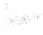
- FIG. 1 is an exploded view of the present invention
- FIG. 2 is a sectional view of the faucet body of the present invention.
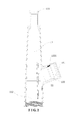
- FIG. 3 is a sectional view of the present invention.
- the present invention discloses a mounting structure for a faucet body and a shaft, which comprises a faucet body 1 , a shaft seat assembly 2 mounted in the faucet body 1 , a shaft 3 and a press cover 4 mounted to the shaft seat assembly 2 .
- the faucet body 1 is made of a zinc alloy material.
- the faucet body 1 is formed with a vertical passage 11 and a mounting passage 12 communicating with the vertical passage 11 .
- the vertical passage 11 has an upper opening 111 and a lower opening 112 .
- An inner end of the mounting passage 12 is communicated with the vertical passage 11 .
- An outer end of the mounting passage 12 has an opening 121 .
- An inner wall of the mounting passage 12 is formed with an annular stop rim 122 .
- the annular stop rim 122 is provided with at least two screw holes 1221 extending in the axial direction of the mounting passage 12 for insertion of screws 5 .
- the number of the screw holes 1221 may be three.
- the three screw holes 1221 are equidistantly arranged on the annular stop rim 122 .
- the shaft seat assembly 2 is disposed separately from the faucet body 1 .
- the shaft seat assembly 2 includes a shaft seat 21 located in the vertical passage 11 of the faucet body 1 and a sleeve 22 located in the mounting passage 12 .
- the shaft seat 21 is integrally formed with the sleeve 22 .
- the shaft seat 21 has a water inlet channel and a water outlet channel to communicate with an inner chamber of the sleeve 22 .
- An outer wall of the sleeve 22 is formed with an annular flange 221 extending outwardly.
- the annular flange 221 is in contact with the annular stop rim 122 .
- the annular flange 221 is provided with through holes 2211 corresponding to the screw holes 1221 .
- the screws 5 pass through the through holes 2211 of the annular flange 221 and are screwed to the screw holes 1221 of the annular stop rim 122 so that the sleeve 22 is secured in the mounting passage 12 to prevent the sleeve 22 from being rotated and moved.
- the shaft seat assembly 2 may be made of a copper material or a copper alloy material. Since the material of the faucet body 1 is a zinc alloy material, in order to avoid electrochemical corrosion between the shaft seat assembly 2 and the faucet body 1 , a plastic washer 6 is provided between the annular stop rim 122 of the faucet body 1 and the annular flange 221 of the sleeve 22 .
- the plastic washer 6 has guide holes 61 corresponding to the screw holes 1221 .
- the plastic washer 6 can separate the shaft seat assembly 2 from the faucet body 1 so as to prevent electrochemical corrosion between the two.
- the annular flange 221 is provided with a limit hole 2212
- the plastic washer 6 is provided with a limit protrusion 62 to mate with the limit hole 2212 .
- the material of the shaft seat assembly 2 is not limited to a copper material or copper alloy material.
- the shaft seat assembly 2 may be made of a plastic material, which can prevent electrochemical corrosion between the shaft seat assembly 2 and the faucet body 1 and ensure the safety of the water.
- the press cover 4 has a central hole 41 .
- the press cover 4 is threadedly connected to the sleeve 22 .
- the screwing engagement between the press cover 4 and the sleeve 22 may be that the peripheral wall of the press cover 4 is provided with external threads and the inner wall of the sleeve 22 is provided with internal threads to mate with the external threads of the press cover 4 .
- the screwing engagement between the press cover 4 and the sleeve 22 may be that the peripheral wall of the press cover 4 is provided with internal threads and the outer wall of the sleeve 22 is provided with external threads to mate with the internal threads of the press cover 4 .
- the shaft 3 is inserted in the sleeve 22 and located between the press cover 4 and the shaft seat 21 .
- An axle 31 of the shaft 3 extends out of the central hole 41 of the press cover 4 for subsequent engagement with a handle to operate the shaft 3 .
- the specific structure of the shaft 3 is the prior art, and will not be described hereinafter.
- the shaft 3 is first inserted in the sleeve 22 of the shaft seat assembly 2 , and then the press cover 4 is screwed to the sleeve 22 to limit the shaft 3 in the sleeve 22 .
- the axle 31 of the shaft 3 passes through the central hole 41 of the press cover 4 .
- the plastic washer 6 is fitted onto the annular flange 221 .
- the shaft seat assembly 2 fitted with the shaft 3 and the press cover 4 is placed into the faucet body 1 from the opening 121 of the mounting passage 12 , so that the annular flange 221 abuts against the annular stop rim 122 .
- the plastic washer 6 is sandwiched between the annular flange 221 and the annular stop rim 122 .
- the shaft seat 21 of the shaft seat assembly 2 is located in the vertical passage 11 .
- the sleeve 22 is located in the mounting passage 12 .
- the screws 5 are inserted through the through holes 2211 and the screw holes 1221 to lock the shaft seat assembly 2 .
- the shaft seat assembly 2 is disposed separately from the faucet body 1 so that the faucet body 1 is not in contact with water; and the faucet body 1 is made of a zinc alloy material with high strength and low price.
- the present invention can reduce the material cost of the faucet body 1 and ensure the water quality and the strength of the faucet body 1 .
Landscapes
- Engineering & Computer Science (AREA)
- General Engineering & Computer Science (AREA)
- Mechanical Engineering (AREA)
- Health & Medical Sciences (AREA)
- Life Sciences & Earth Sciences (AREA)
- Hydrology & Water Resources (AREA)
- Public Health (AREA)
- Water Supply & Treatment (AREA)
- Domestic Plumbing Installations (AREA)
Abstract
Description
Claims (4)
Applications Claiming Priority (3)
| Application Number | Priority Date | Filing Date | Title |
|---|---|---|---|
| CN201710896294 | 2017-09-28 | ||
| CN201710896294.4 | 2017-09-28 | ||
| CN201710896294.4A CN107524841B (en) | 2017-09-28 | 2017-09-28 | Mounting structure of tap body and bolt shaft |
Publications (2)
| Publication Number | Publication Date |
|---|---|
| US10240325B1 true US10240325B1 (en) | 2019-03-26 |
| US20190093323A1 US20190093323A1 (en) | 2019-03-28 |
Family
ID=60737474
Family Applications (1)
| Application Number | Title | Priority Date | Filing Date |
|---|---|---|---|
| US15/871,108 Active US10240325B1 (en) | 2017-09-28 | 2018-01-15 | Mounting structure for faucet body and shaft |
Country Status (2)
| Country | Link |
|---|---|
| US (1) | US10240325B1 (en) |
| CN (1) | CN107524841B (en) |
Cited By (7)
| Publication number | Priority date | Publication date | Assignee | Title |
|---|---|---|---|---|
| USD1032788S1 (en) | 2022-07-07 | 2024-06-25 | Xiamen Lota International Co., Ltd. | Kitchen faucet |
| USD1038330S1 (en) | 2022-04-19 | 2024-08-06 | Xiamen Lota International Co., Ltd. | Kitchen faucet |
| USD1038331S1 (en) | 2022-04-19 | 2024-08-06 | Xiamen Lota International Co., Ltd. | Kitchen faucet |
| USD1039115S1 (en) | 2022-04-19 | 2024-08-13 | Xiamen Lota International Co., Ltd. | Bathroom faucet |
| USD1069987S1 (en) | 2022-01-07 | 2025-04-08 | Xiamen Lota International Co., Ltd. | Bathroom faucet |
| USD1073021S1 (en) | 2022-01-07 | 2025-04-29 | Xiamen Lota International Co., Ltd. | Bathroom faucet |
| USD1086394S1 (en) | 2023-10-27 | 2025-07-29 | Xiamen Lota International Co., Ltd. | Faucet |
Families Citing this family (1)
| Publication number | Priority date | Publication date | Assignee | Title |
|---|---|---|---|---|
| CN110332352A (en) * | 2019-07-25 | 2019-10-15 | 路达(厦门)工业有限公司 | A kind of tap |
Citations (10)
| Publication number | Priority date | Publication date | Assignee | Title |
|---|---|---|---|---|
| US5979487A (en) * | 1994-07-11 | 1999-11-09 | Fmc Corporation | Manual selective connection installation which can be cleaned by scraping |
| US6386226B1 (en) * | 2001-02-15 | 2002-05-14 | Moen Incorporated | Single handle lavatory faucet with handle collar for seating valve assembly |
| US6757921B2 (en) * | 2002-07-16 | 2004-07-06 | Kohler Co. | Pull-out faucet |
| US20110297248A1 (en) * | 2009-02-27 | 2011-12-08 | Mercury Plastics, Inc. | Faucet manifold |
| US8240326B2 (en) * | 2009-06-30 | 2012-08-14 | Moen Incorporated | Faucet with assembly and retention features |
| US8453669B2 (en) * | 2010-07-21 | 2013-06-04 | Masco Corporation Of Indiana | Waterway adapter |
| US8863780B2 (en) * | 2009-05-08 | 2014-10-21 | Kohler Co. | Corrosion resistant faucets with components made of different metallic materials |
| US8925572B2 (en) * | 2013-02-08 | 2015-01-06 | Tai-World Mfg. Co., Ltd. | Connecting structure of a faucet body and a control valve |
| US20150376737A1 (en) * | 2013-03-07 | 2015-12-31 | Grohe Ag | Copper-zinc alloy for a plumbing fitting and method for the production thereof |
| US9279238B2 (en) * | 2013-03-07 | 2016-03-08 | Grohe Ag | Plumbing fixture having a tensioning member |
Family Cites Families (8)
| Publication number | Priority date | Publication date | Assignee | Title |
|---|---|---|---|---|
| FR1313046A (en) * | 1962-02-01 | 1962-12-21 | Rokal Gmbh | Distributor and mixer tap for cold and hot water |
| US6179130B1 (en) * | 1997-08-08 | 2001-01-30 | Emhart Inc. | Faucet spout assembly |
| TWM247746U (en) * | 2003-09-04 | 2004-10-21 | Deluxe Brassware Co Ltd | Dual purpose upright faucet for kitchen |
| CN202048270U (en) * | 2011-03-25 | 2011-11-23 | 路达(厦门)工业有限公司 | Structure for fixing waterway of faucet body set of widespread faucet |
| CN203248805U (en) * | 2013-05-09 | 2013-10-23 | 开平市德尔斐卫浴科技实业有限公司 | Faucet with plastic valve plug |
| CN107542955A (en) * | 2017-09-28 | 2018-01-05 | 路达(厦门)工业有限公司 | A kind of fixed structure of faucet body and stud shaft |
| CN207394062U (en) * | 2017-09-28 | 2018-05-22 | 路达(厦门)工业有限公司 | A kind of fixed structure of faucet body and stud shaft |
| CN207394063U (en) * | 2017-09-28 | 2018-05-22 | 路达(厦门)工业有限公司 | A kind of mounting structure of faucet body and stud shaft |
-
2017
- 2017-09-28 CN CN201710896294.4A patent/CN107524841B/en active Active
-
2018
- 2018-01-15 US US15/871,108 patent/US10240325B1/en active Active
Patent Citations (10)
| Publication number | Priority date | Publication date | Assignee | Title |
|---|---|---|---|---|
| US5979487A (en) * | 1994-07-11 | 1999-11-09 | Fmc Corporation | Manual selective connection installation which can be cleaned by scraping |
| US6386226B1 (en) * | 2001-02-15 | 2002-05-14 | Moen Incorporated | Single handle lavatory faucet with handle collar for seating valve assembly |
| US6757921B2 (en) * | 2002-07-16 | 2004-07-06 | Kohler Co. | Pull-out faucet |
| US20110297248A1 (en) * | 2009-02-27 | 2011-12-08 | Mercury Plastics, Inc. | Faucet manifold |
| US8863780B2 (en) * | 2009-05-08 | 2014-10-21 | Kohler Co. | Corrosion resistant faucets with components made of different metallic materials |
| US8240326B2 (en) * | 2009-06-30 | 2012-08-14 | Moen Incorporated | Faucet with assembly and retention features |
| US8453669B2 (en) * | 2010-07-21 | 2013-06-04 | Masco Corporation Of Indiana | Waterway adapter |
| US8925572B2 (en) * | 2013-02-08 | 2015-01-06 | Tai-World Mfg. Co., Ltd. | Connecting structure of a faucet body and a control valve |
| US20150376737A1 (en) * | 2013-03-07 | 2015-12-31 | Grohe Ag | Copper-zinc alloy for a plumbing fitting and method for the production thereof |
| US9279238B2 (en) * | 2013-03-07 | 2016-03-08 | Grohe Ag | Plumbing fixture having a tensioning member |
Cited By (7)
| Publication number | Priority date | Publication date | Assignee | Title |
|---|---|---|---|---|
| USD1069987S1 (en) | 2022-01-07 | 2025-04-08 | Xiamen Lota International Co., Ltd. | Bathroom faucet |
| USD1073021S1 (en) | 2022-01-07 | 2025-04-29 | Xiamen Lota International Co., Ltd. | Bathroom faucet |
| USD1038330S1 (en) | 2022-04-19 | 2024-08-06 | Xiamen Lota International Co., Ltd. | Kitchen faucet |
| USD1038331S1 (en) | 2022-04-19 | 2024-08-06 | Xiamen Lota International Co., Ltd. | Kitchen faucet |
| USD1039115S1 (en) | 2022-04-19 | 2024-08-13 | Xiamen Lota International Co., Ltd. | Bathroom faucet |
| USD1032788S1 (en) | 2022-07-07 | 2024-06-25 | Xiamen Lota International Co., Ltd. | Kitchen faucet |
| USD1086394S1 (en) | 2023-10-27 | 2025-07-29 | Xiamen Lota International Co., Ltd. | Faucet |
Also Published As
| Publication number | Publication date |
|---|---|
| US20190093323A1 (en) | 2019-03-28 |
| CN107524841B (en) | 2024-04-19 |
| CN107524841A (en) | 2017-12-29 |
Similar Documents
| Publication | Publication Date | Title |
|---|---|---|
| US10240325B1 (en) | Mounting structure for faucet body and shaft | |
| US20160333555A1 (en) | Environmental faucet and method for producing the same | |
| US10213800B2 (en) | Spray head | |
| CA2644557A1 (en) | Spa jet with screw in jet barrel | |
| CN112443674B (en) | Tap goes out water component | |
| US7647939B2 (en) | Water inlet device for a faucet | |
| US9822515B2 (en) | Flow-control faucet aerator | |
| US20190194917A1 (en) | Drinking water faucet | |
| US20150136257A1 (en) | Control Valve Structure for a Faucet | |
| CN110242769B (en) | Tap for water purifier | |
| US8037558B1 (en) | Wash basin drain structure | |
| CN201507719U (en) | Faucet split valve seat | |
| CN207394062U (en) | A kind of fixed structure of faucet body and stud shaft | |
| CN207394063U (en) | A kind of mounting structure of faucet body and stud shaft | |
| US20130048122A1 (en) | Single handle faucet and a connecting structure thereof | |
| US10125477B2 (en) | Faucet structure | |
| US20170306597A1 (en) | Washer with an adjustable inlet aperture for different water pressure | |
| US9670655B2 (en) | Valve assembly for faucet | |
| US10214884B1 (en) | Basin faucet | |
| US9423038B1 (en) | Switching valve structure for a faucet | |
| CN107542955A (en) | A kind of fixed structure of faucet body and stud shaft | |
| US20190063047A1 (en) | Water pipe structure of basin faucet | |
| CN210240710U (en) | Simple to operate's water purifier tap shell | |
| CN109854757B (en) | Anti-disassembly drinking water device | |
| CN208734933U (en) | A kind of tap easy to assembly |
Legal Events
| Date | Code | Title | Description |
|---|---|---|---|
| FEPP | Fee payment procedure |
Free format text: ENTITY STATUS SET TO UNDISCOUNTED (ORIGINAL EVENT CODE: BIG.); ENTITY STATUS OF PATENT OWNER: LARGE ENTITY |
|
| AS | Assignment |
Owner name: LOTA XIAMEN INDUSTRY CO., LTD., CHINA Free format text: ASSIGNMENT OF ASSIGNORS INTEREST;ASSIGNORS:ZHU, CHUANBAO;HE, YONGQIANG;YE, XIANQING;REEL/FRAME:044624/0316 Effective date: 20180105 Owner name: XIAMEN LOTA INTERNATIONAL CO., LTD., CHINA Free format text: ASSIGNMENT OF ASSIGNORS INTEREST;ASSIGNORS:ZHU, CHUANBAO;HE, YONGQIANG;YE, XIANQING;REEL/FRAME:044624/0316 Effective date: 20180105 |
|
| STCF | Information on status: patent grant |
Free format text: PATENTED CASE |
|
| MAFP | Maintenance fee payment |
Free format text: PAYMENT OF MAINTENANCE FEE, 4TH YEAR, LARGE ENTITY (ORIGINAL EVENT CODE: M1551); ENTITY STATUS OF PATENT OWNER: LARGE ENTITY Year of fee payment: 4 |