US10224593B2 - Support assembly and satellite antenna module using the same - Google Patents
Support assembly and satellite antenna module using the same Download PDFInfo
- Publication number
- US10224593B2 US10224593B2 US15/217,146 US201615217146A US10224593B2 US 10224593 B2 US10224593 B2 US 10224593B2 US 201615217146 A US201615217146 A US 201615217146A US 10224593 B2 US10224593 B2 US 10224593B2
- Authority
- US
- United States
- Prior art keywords
- adapter
- section
- support assembly
- upper plate
- location hole
- Prior art date
- Legal status (The legal status is an assumption and is not a legal conclusion. Google has not performed a legal analysis and makes no representation as to the accuracy of the status listed.)
- Active, expires
Links
Images




Classifications
-
- H—ELECTRICITY
- H01—ELECTRIC ELEMENTS
- H01Q—ANTENNAS, i.e. RADIO AERIALS
- H01Q1/00—Details of, or arrangements associated with, antennas
- H01Q1/12—Supports; Mounting means
- H01Q1/1207—Supports; Mounting means for fastening a rigid aerial element
- H01Q1/1221—Supports; Mounting means for fastening a rigid aerial element onto a wall
-
- F—MECHANICAL ENGINEERING; LIGHTING; HEATING; WEAPONS; BLASTING
- F16—ENGINEERING ELEMENTS AND UNITS; GENERAL MEASURES FOR PRODUCING AND MAINTAINING EFFECTIVE FUNCTIONING OF MACHINES OR INSTALLATIONS; THERMAL INSULATION IN GENERAL
- F16M—FRAMES, CASINGS OR BEDS OF ENGINES, MACHINES OR APPARATUS, NOT SPECIFIC TO ENGINES, MACHINES OR APPARATUS PROVIDED FOR ELSEWHERE; STANDS; SUPPORTS
- F16M13/00—Other supports for positioning apparatus or articles; Means for steadying hand-held apparatus or articles
- F16M13/02—Other supports for positioning apparatus or articles; Means for steadying hand-held apparatus or articles for supporting on, or attaching to, an object, e.g. tree, gate, window-frame, cycle
-
- H—ELECTRICITY
- H01—ELECTRIC ELEMENTS
- H01Q—ANTENNAS, i.e. RADIO AERIALS
- H01Q1/00—Details of, or arrangements associated with, antennas
- H01Q1/12—Supports; Mounting means
- H01Q1/1207—Supports; Mounting means for fastening a rigid aerial element
-
- H—ELECTRICITY
- H01—ELECTRIC ELEMENTS
- H01Q—ANTENNAS, i.e. RADIO AERIALS
- H01Q1/00—Details of, or arrangements associated with, antennas
- H01Q1/12—Supports; Mounting means
- H01Q1/125—Means for positioning
-
- H—ELECTRICITY
- H01—ELECTRIC ELEMENTS
- H01Q—ANTENNAS, i.e. RADIO AERIALS
- H01Q15/00—Devices for reflection, refraction, diffraction or polarisation of waves radiated from an antenna, e.g. quasi-optical devices
- H01Q15/14—Reflecting surfaces; Equivalent structures
- H01Q15/16—Reflecting surfaces; Equivalent structures curved in two dimensions [2D], e.g. paraboloidal
-
- H—ELECTRICITY
- H01—ELECTRIC ELEMENTS
- H01Q—ANTENNAS, i.e. RADIO AERIALS
- H01Q19/00—Combinations of primary active antenna elements and units with secondary devices, e.g. with quasi-optical devices, for giving the antenna a desired directional characteristic
- H01Q19/10—Combinations of primary active antenna elements and units with secondary devices, e.g. with quasi-optical devices, for giving the antenna a desired directional characteristic using reflecting surfaces
- H01Q19/12—Combinations of primary active antenna elements and units with secondary devices, e.g. with quasi-optical devices, for giving the antenna a desired directional characteristic using reflecting surfaces wherein the surfaces are concave
- H01Q19/13—Combinations of primary active antenna elements and units with secondary devices, e.g. with quasi-optical devices, for giving the antenna a desired directional characteristic using reflecting surfaces wherein the surfaces are concave the primary radiating source being a single radiating element, e.g. a dipole, a slot, a waveguide termination
-
- H—ELECTRICITY
- H01—ELECTRIC ELEMENTS
- H01Q—ANTENNAS, i.e. RADIO AERIALS
- H01Q3/00—Arrangements for changing or varying the orientation or the shape of the directional pattern of the waves radiated from an antenna or antenna system
- H01Q3/02—Arrangements for changing or varying the orientation or the shape of the directional pattern of the waves radiated from an antenna or antenna system using mechanical movement of antenna or antenna system as a whole
- H01Q3/04—Arrangements for changing or varying the orientation or the shape of the directional pattern of the waves radiated from an antenna or antenna system using mechanical movement of antenna or antenna system as a whole for varying one co-ordinate of the orientation
- H01Q3/06—Arrangements for changing or varying the orientation or the shape of the directional pattern of the waves radiated from an antenna or antenna system using mechanical movement of antenna or antenna system as a whole for varying one co-ordinate of the orientation over a restricted angle
-
- F—MECHANICAL ENGINEERING; LIGHTING; HEATING; WEAPONS; BLASTING
- F16—ENGINEERING ELEMENTS AND UNITS; GENERAL MEASURES FOR PRODUCING AND MAINTAINING EFFECTIVE FUNCTIONING OF MACHINES OR INSTALLATIONS; THERMAL INSULATION IN GENERAL
- F16B—DEVICES FOR FASTENING OR SECURING CONSTRUCTIONAL ELEMENTS OR MACHINE PARTS TOGETHER, e.g. NAILS, BOLTS, CIRCLIPS, CLAMPS, CLIPS OR WEDGES; JOINTS OR JOINTING
- F16B2/00—Friction-grip releasable fastenings
- F16B2/02—Clamps, i.e. with gripping action effected by positive means other than the inherent resistance to deformation of the material of the fastening
- F16B2/06—Clamps, i.e. with gripping action effected by positive means other than the inherent resistance to deformation of the material of the fastening external, i.e. with contracting action
- F16B2/10—Clamps, i.e. with gripping action effected by positive means other than the inherent resistance to deformation of the material of the fastening external, i.e. with contracting action using pivoting jaws
-
- F—MECHANICAL ENGINEERING; LIGHTING; HEATING; WEAPONS; BLASTING
- F16—ENGINEERING ELEMENTS AND UNITS; GENERAL MEASURES FOR PRODUCING AND MAINTAINING EFFECTIVE FUNCTIONING OF MACHINES OR INSTALLATIONS; THERMAL INSULATION IN GENERAL
- F16H—GEARING
- F16H25/00—Gearings comprising primarily only cams, cam-followers and screw-and-nut mechanisms
- F16H25/18—Gearings comprising primarily only cams, cam-followers and screw-and-nut mechanisms for conveying or interconverting oscillating or reciprocating motions
- F16H25/20—Screw mechanisms
Definitions
- the present invention relates to a communication device and elements thereof, and more particularly to a satellite antenna module and a support assembly thereof.
- satellite such as broadcast television, weather maps, communication, and so on.
- Being able to adjust a satellite antenna to receive satellite signals is critical during the installation of the satellite antenna.
- signals transmitted from the satellite antenna may have optimal strengths, and can be transmitted in severe weather conditions as well.
- the transceiver of a traditional conventional dish satellite antenna includes a dish reflector for focusing satellite signals to be received, and at least one low noise signal amplifier (LNBF) for receiving the focused signals.
- LNBF low noise signal amplifier
- the longitude and latitude of the antenna dish and the angle between the antenna dish and the satellite should be carefully checked and precisely positioned.
- an antenna dish of a satellite antenna is installed on a support assembly.
- the support assembly can be easily deformed and knocked over by an external force. Therefore, if the antenna dish is installed outdoor and suffers strong winds, the support assembly may lose its correct receiving orientation, or may be damaged due to a collapse.
- one aspect of the present invention is to provide a support assembly that is easy to assemble.
- the other aspect of the present invention is to provide a more compact support assembly with higher reliability so as to be used in different weather conditions.
- the support assembly includes an adapter, a stand, and a dish backing structure.
- the adapter includes two side plates and an upper plate. The side plates are respectively located at the two sides of the adapter.
- the upper plate is connected to the side plates and has a lower location hole.
- the stand is connected to the adapter.
- the dish backing structure has a receiving portion which is capable of receiving the adapter and includes two side walls and a top wall. The side walls are respectively located at the both sides of the receiving portion.
- the top wall is connected to the side walls and has an upper location hole, a first section and a second section. When the receiving portion is connected to the adapter, the second section abuts against the top wall, the first section and the upper plate of the adapter define a gap, and the upper location hole is aligned with the lower location hole.
- the satellite antenna module includes an antenna dish disposed on the dish backing structure of the support assembly.
- FIG. 1 shows a schematic view of a satellite antenna module, in accordance with one embodiment of the disclosure.
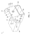
- FIG. 2 shows a schematic view of an adapter, in accordance with one embodiment of the disclosure.
- FIG. 3 shows a schematic view of a dish backing structure, in accordance with one embodiment of the disclosure.
- FIG. 4 shows a side view of a receiving portion, in accordance with one embodiment of the disclosure.
- FIGS. 5A-5D show steps of assembling a support assembly, in accordance with one embodiment of the disclosure.
- FIG. 6 shows a cross-sectional schematic view of partial elements of the satellite antenna module as an adapter being connected to the dish backing structure, in accordance with one embodiment of the disclosure.
- FIG. 7 shows a schematic view of a dish backing structure, in accordance with one embodiment of the disclosure.
- FIG. 8 shows a schematic view of a dish backing structure, in accordance with one embodiment of the disclosure.
- FIG. 1 shows a schematic view of a satellite antenna module 1 , in accordance with one embodiment of the disclosure.
- the satellite antenna module 1 includes an antenna dish 2 for receiving and reflecting the satellite signals and a support assembly 3 .
- the support assembly 3 is disposed on a fixed plane, such as an outer wall of a building or a ground, and the antenna dish 2 is held by the support assembly 3 . In this manner, the antenna dish 2 is disposed on the fixed plane stably with the support assembly 3 even if being used in severe weather conditions.
- the structural features of the support assembly 3 in accordance with one embodiment of the disclosure are described below.
- the support assembly 3 includes a dish backing structure 32 , an adapter 31 , a stand 34 connected to the adapter 31 for connecting the dish backing structure 32 and the adapter 31 to a wall, and a fastening member 33 for fixing the dish backing structure 32 and the adapter 31 .
- the elements of the support assembly 3 can be added to or omitted, and the invention should not be limited by the embodiment.
- FIG. 2 shows a schematic view of the adapter 31 , in accordance with one embodiment of the disclosure.
- the adapter 31 includes an upper plate 36 , two side plates 37 , and two C-shaped hook structures 39 .
- the elements of the adapter 31 can be added to or omitted, and the invention should not be limited by the embodiment.
- the upper plate 36 is a rectangular plate and has a front edge 361 , a rear edge 362 , and two lateral edges 363 and 364 .
- the rear edge 362 is adjacent to the stand 34
- the front edge 361 is opposite to the rear edge 362 .
- the two lateral edges 363 and 364 are connected between the front edge 361 and the rear edge 362 .
- a lower location hole 365 penetrates the upper plate 36 .
- the lower location hole 365 can be spaced from the lateral edge 363 and the lateral edge 364 by the same distance. Nonetheless, the disclosure should not be limited thereto.
- the lower location hole 365 can be spaced from the lateral edge 363 and the lateral edge 364 by different distances as well.
- the two side plates 37 are respectively connected to two opposite lateral edges 363 and 364 , and are connected to the stand 34 .
- the two hook structures 39 are adjacent to the front edge 361 of the upper plate 36 and respectively connected to the two lateral edges 363 and 364 .
- the two hook structures 39 are extended and bent in a direction away from the side plates 37 and away from the upper plate 36 , where the two hook structures 39 respectively define two rotation openings 391 .
- the two side plates 37 may be fixed on one end of the stand 34 by any suitable method (such as screwing or riveting).
- the stand 34 , the upper plate 36 , the two side plates 37 , and the two hook structures 39 can be formed integrally as well.
- two notches 366 are formed at the front edge 361 of the upper plate 36 .
- the number of the notches 366 may be altered according to different needs.
- the number of the notch 366 formed at the front edge 361 of the upper plate 36 can be one, two or more, or even none.
- FIG. 3 shows a schematic view of a dish backing structure 32 , in accordance with one embodiment of the disclosure.
- the dish backing structure 32 is configured to support the antenna dish 2 (see FIG. 1 ).
- the dish backing structure 32 has a dish-shaped structure 41 , a receiving portion 42 , and numerous positioning structures, including two first positioning structures 46 and two second positioning structures 47 .
- the receiving portion 42 includes a top wall 43 , and two side walls 44 .
- the top wall 43 extends outwardly from one side of the dish-shaped structure 41 .
- the top wall 43 is a rectangular-shaped plate and has a front edge 431 , a rear edge 432 , and two lateral edges 433 and 434 .
- the rear edge 432 is connected to the dish-shaped structure 41
- the front edge 431 is opposite to the rear edge 432 .
- the two lateral edges 433 and 434 are connected between the front edge 431 and the rear edge 432 .
- An upper location hole 437 penetrates the top wall 43 .
- the two side walls 44 extend outwardly from one side of the dish-shaped structure 41 and are respectively connected to the two lateral edges 433 and 434 .
- Each of the two side walls 44 has an inner surface 441 ( FIG. 4 ) facing one another. As shown in FIG.
- a channel 420 extending along an axis C is defined by the top wall 43 and the two side walls 44 .
- the top wall 43 may be made of materials such as steel or aluminum alloy.
- the side walls 44 may be made of the same material as the top wall 43 .
- the top wall 43 is divided into a first section 435 and two second section 436 .
- the front boundary and the rear boundary of the first section 435 are respectively located on the front edge 431 and the rear edge 432 , and the right boundary and the left boundary of the first section 435 is spaced from the two lateral edges 433 and 434 by a distance.
- the two second sections 436 are respectively located between two sides of the first section 435 and the lateral edges 433 and 434 , in which the front boundary and the rear boundary of each of the two second sections 436 are respectively located on the front edge 431 and the rear edge 432 .
- the upper location hole 437 penetrates the first section 435 of the top wall 43 .
- the upper location hole 437 can be spaced from the lateral edge 433 and the lateral edge 434 by the same distance. Nonetheless, the disclosure should not be limited thereto; the upper location hole 437 may also be spaced from the lateral edge 433 and the lateral edge 434 by different distances.
- FIG. 4 shows a side view of a receiving portion, in accordance with one embodiment of the disclosure.
- the lower surface of the first section 435 of the top wall 43 extends along a first plane P 1
- the lower surfaces of the two second sections 436 extend along a second plane P 2 parallel to the first plane P 1 .
- the distance between the first plane P 1 and the second plane P 2 is greater than 0 mm and smaller than or equal to the thickness of the top wall 43 .
- Two first positioning structures 46 are configured to limit the movement of the adapter 31 in a direction parallel to the top wall 43 .
- the two first positioning structures 46 are formed on an inner surface 438 of the top wall 43 and corresponding to the first section 435 .
- the two first positioning structures are positioning blocks. The shape and the size of each positioning block correspond to that of the corresponding notch 366 .
- the number of the first positioning structures 46 may be altered.
- the number of the first positioning structures 46 formed at the inner surface 438 of the top wall 43 can be one, two or more, or even none.
- Two second positioning structures 47 are configured to limit the movement of the adapter 31 in a direction parallel to the side walls 44 .
- the two second positioning structures 47 are formed on the inner surfaces 441 of the side walls 44 .
- the two second positioning structures 47 are pivoting shafts.
- the shape and the size of each of the second positioning structures 47 correspond to that of the rotation opening 391 , so that the rotation opening 391 can be detachably and pivotably connected to the pivoting shafts 47 .
- first positioning structure is referred to “positioning block”
- second positioning structure is referred to “pivoting shaft”.
- FIGS. 5A-5D show steps for assembling the support assembly 3 , in accordance with one embodiment of the disclosure.
- FIG. 5A First, as shown in FIG. 5A , insert the adapter 31 into the channel 420 of the dish backing structure 32 along a direction A as indicated in FIG. 5A . Afterwards, as shown in FIG. 5B , hook the rotation openings 391 of the hook structures 39 onto the pivoting shafts 47 .
- the adapter 31 rotates in a direction B as indicated in FIG. 5B , so that the hook structures 39 are rotated about the pivoting shaft 47 .
- the rotation is not stopped until the positioning blocks 46 engage the notches 366 formed on the adapter 31 and the movement of the adapter 31 in direction T toward the dish backing structure 32 is limited as the positioning blocks 46 are abutted against the notches 366 , as shown in FIG. 5C .
- the upper plate 36 of the adapter 31 is positioned to be adjacent to the top wall 43 of the receiving portion 42
- the two side plates 37 are positioned to be adjacent to the two side walls 44 (only one side plane 37 and one side wall 44 are shown in FIG. 5C ).
- the lower location hole 365 on the upper plate 36 is aligned to the upper location hole 437 .
- a fastening member 33 (such as a screw) is inserted through the upper location hole 437 and the lower location hole 365 so as to connect the adapter 31 to the dish backing structure 32 .
- the top wall 43 of the receiving portion 42 is not entirely in contact with the adapter 31 .
- the adapter 31 is connected to the dish backing structure 32 by the fastening member 33 , while the second sections 436 of the top wall 43 are directly in contact with the top plate 36 , the first section 435 of the top wall 43 is not in contact with the top plate 36 , and a gap G is defined therebetween.
- the adapter 31 and the dish backing structure 32 serve as a spring disc to avoid disengagement of the fastening member 33 , as the dish backing structure 32 vibrates relative to the adapter 31 or as the dish backing structure 32 is drawn violently by a heavy external force caused by strong winds or the like. As a result, the antenna dish 2 is prevented from being offset from the preset position.
- top wall 43 of the dish backing structure 32 should not be limited to the above-mentioned embodiments.
- the positions of the first section 435 and the second sections 436 formed on the top wall 43 may be changed.
- some exemplary possible implementation structures of the top walls 43 will be illustrated.
- the top wall 43 a of the dish backing structure 32 a includes a first section 435 a and a second section 436 a .
- the first section 435 a is located at the substantial center of the top wall 43 a
- the second section 436 a surrounds the first section 435 a .
- the second section 436 a is adjacent to the front edge 431 a , the rear edge 432 a , and the two lateral edges 433 a and 434 a.
- the top wall 43 b of the dish backing structure 32 b includes a first section 435 b and two second sections 436 b .
- the right boundary and the left boundary of the first section 435 b are located at the two lateral edges 433 b and 434 b
- the front boundary and the rear boundary of the first section 435 b are spaced from the front edge 431 b and the rear edge 432 b by a distance.
- the right boundary and the left boundary of each of the second sections 436 b are located at the two lateral edges 433 b and 434 b
- the two planes 436 b are arranged between the first section 435 b and the front edge 431 b and the rear edge 432 b.
- Embodiments of the support assembly in the disclosure include a dish backing structure having a top wall with height difference, and thus after the assembly of the support assembly, the top wall is not entirely in contact with an upper plate of an adapter. As a result, a buffer displacement is created between the dish backing structure and the adapter to protect the support assembly from being damaged by external force. In addition, with the arrangement of the positioning structures, the support assembly is assembled efficiently, and misalignment of the dish backing structure caused by inaccurate assembly is also avoided.
Landscapes
- Engineering & Computer Science (AREA)
- General Engineering & Computer Science (AREA)
- Physics & Mathematics (AREA)
- Electromagnetism (AREA)
- Mechanical Engineering (AREA)
- Connection Of Plates (AREA)
- Support Of Aerials (AREA)
Abstract
Description
Claims (12)
Applications Claiming Priority (3)
| Application Number | Priority Date | Filing Date | Title |
|---|---|---|---|
| TW104136134A | 2015-11-03 | ||
| TW104136134 | 2015-11-03 | ||
| TW104136134A TWI572087B (en) | 2015-11-03 | 2015-11-03 | Support assembly and satellite antenna module using the same |
Publications (2)
| Publication Number | Publication Date |
|---|---|
| US20170125876A1 US20170125876A1 (en) | 2017-05-04 |
| US10224593B2 true US10224593B2 (en) | 2019-03-05 |
Family
ID=58608561
Family Applications (1)
| Application Number | Title | Priority Date | Filing Date |
|---|---|---|---|
| US15/217,146 Active 2037-04-22 US10224593B2 (en) | 2015-11-03 | 2016-07-22 | Support assembly and satellite antenna module using the same |
Country Status (2)
| Country | Link |
|---|---|
| US (1) | US10224593B2 (en) |
| TW (1) | TWI572087B (en) |
Families Citing this family (3)
| Publication number | Priority date | Publication date | Assignee | Title |
|---|---|---|---|---|
| US9660320B2 (en) | 2015-06-10 | 2017-05-23 | Highlands Diversified Services, Inc. | High efficiency mounting assembly for satellite dish reflector |
| USD883266S1 (en) * | 2017-08-28 | 2020-05-05 | Wistron Neweb Corp. | Satellite dish backing structure |
| CN109520438A (en) * | 2018-11-23 | 2019-03-26 | 梅州市志浩电子科技有限公司 | The inclined distance measurement method in the hole of machine drilling |
Citations (8)
| Publication number | Priority date | Publication date | Assignee | Title |
|---|---|---|---|---|
| US7411562B2 (en) | 2006-10-19 | 2008-08-12 | Ming-Tien Lin | Apparatus for supporting a satellite antenna dish and a satellite receiver |
| US20100249513A1 (en) | 2009-03-31 | 2010-09-30 | Jay Tydlaska | Laryngoscope and system |
| TWM435807U (en) | 2012-04-03 | 2012-08-11 | Wistron Corp | A shock absorption device and a shock absorption module |
| TWM452471U (en) | 2012-09-27 | 2013-05-01 | Wistron Neweb Corp | Clamp mechanism with easy installation and antenna device therewith |
| TWM455992U (en) | 2013-02-08 | 2013-06-21 | Wistron Neweb Corp | Satellite antenna module and its angle adjustment device |
| TWM455659U (en) | 2012-09-24 | 2013-06-21 | Wistron Neweb Corp | Bridging mechanism for connecting a supporting tube and a holder and antenna device therewith |
| TWM468034U (en) | 2013-06-25 | 2013-12-11 | Azure Shine Int Inc | Satellite antenna angle adjustment device |
| US20140306072A1 (en) * | 2011-06-28 | 2014-10-16 | Wistron Neweb Corporation | Adjusting mechanism and related antenna system |
-
2015
- 2015-11-03 TW TW104136134A patent/TWI572087B/en active
-
2016
- 2016-07-22 US US15/217,146 patent/US10224593B2/en active Active
Patent Citations (10)
| Publication number | Priority date | Publication date | Assignee | Title |
|---|---|---|---|---|
| US7411562B2 (en) | 2006-10-19 | 2008-08-12 | Ming-Tien Lin | Apparatus for supporting a satellite antenna dish and a satellite receiver |
| US20100249513A1 (en) | 2009-03-31 | 2010-09-30 | Jay Tydlaska | Laryngoscope and system |
| US20140306072A1 (en) * | 2011-06-28 | 2014-10-16 | Wistron Neweb Corporation | Adjusting mechanism and related antenna system |
| TWM435807U (en) | 2012-04-03 | 2012-08-11 | Wistron Corp | A shock absorption device and a shock absorption module |
| TWM455659U (en) | 2012-09-24 | 2013-06-21 | Wistron Neweb Corp | Bridging mechanism for connecting a supporting tube and a holder and antenna device therewith |
| US20140084127A1 (en) | 2012-09-24 | 2014-03-27 | Wistron Neweb Corporation | Bridging mechanism for connecting a supporting tube and a holder and antenna device therewith |
| TWM452471U (en) | 2012-09-27 | 2013-05-01 | Wistron Neweb Corp | Clamp mechanism with easy installation and antenna device therewith |
| US20140084121A1 (en) * | 2012-09-27 | 2014-03-27 | Wistron Neweb Corporation | Clamping mechanism with easy assembly and antenna device therewith |
| TWM455992U (en) | 2013-02-08 | 2013-06-21 | Wistron Neweb Corp | Satellite antenna module and its angle adjustment device |
| TWM468034U (en) | 2013-06-25 | 2013-12-11 | Azure Shine Int Inc | Satellite antenna angle adjustment device |
Also Published As
| Publication number | Publication date |
|---|---|
| US20170125876A1 (en) | 2017-05-04 |
| TW201717477A (en) | 2017-05-16 |
| TWI572087B (en) | 2017-02-21 |
Similar Documents
| Publication | Publication Date | Title |
|---|---|---|
| US20170125876A1 (en) | Support assembly and satellite antenna module using the same | |
| JP4170863B2 (en) | Dish antenna rotating device | |
| US9634400B2 (en) | Dish antenna having a self-supporting sub-reflector assembly | |
| US20090121097A1 (en) | Stand for Display Device | |
| US8564498B2 (en) | Variable angle mount for attaching a mast to a structure | |
| US11631929B2 (en) | Fastening device and associated method | |
| US7046210B1 (en) | Precision adjustment antenna mount and alignment method | |
| US20060214865A1 (en) | Antenna Mount With Fine Adjustment Cam | |
| US20230240032A1 (en) | Base station for mounting on ceiling | |
| US11524636B2 (en) | Internally damped crossbar assembly having a slip plate damper | |
| JP5513173B2 (en) | Antenna support device | |
| US20090179115A1 (en) | Retaining ring structure for fixing a satellite antenna | |
| CN1606192B (en) | Fixing structure using a pair of screw members and antenna device having the structure | |
| US8287308B2 (en) | Quick assembly LNBF | |
| US11602060B2 (en) | Rear housing assembly and display device | |
| JP5243326B2 (en) | Support device for receiving device | |
| US8692733B2 (en) | Quick fabrication LNBF assembly | |
| JP5777989B2 (en) | Antenna support device | |
| JP4725378B2 (en) | Parabolic antenna assembly method, assembly jig, and radome mounting bracket | |
| US20180006368A1 (en) | Load-Resistant Antenna Mount | |
| JP2012080362A (en) | Antenna device | |
| JP2012124777A (en) | Parabolic antenna device and radio transmission system using the same | |
| US20120261535A1 (en) | Non-penetrating mount for an antenna | |
| KR102553302B1 (en) | Bracket for joining reflex mirror | |
| KR102065504B1 (en) | Connecting device for PHC pile with improve workability and assembling method of PHC pile using it |
Legal Events
| Date | Code | Title | Description |
|---|---|---|---|
| AS | Assignment |
Owner name: WISTRON NEWEB CORP., TAIWAN Free format text: ASSIGNMENT OF ASSIGNORS INTEREST;ASSIGNORS:YANG, LAN-CHUN;KUO, SAN-YI;KUO, SHUN-CHUNG;AND OTHERS;REEL/FRAME:039304/0695 Effective date: 20160628 |
|
| STCF | Information on status: patent grant |
Free format text: PATENTED CASE |
|
| MAFP | Maintenance fee payment |
Free format text: PAYMENT OF MAINTENANCE FEE, 4TH YEAR, LARGE ENTITY (ORIGINAL EVENT CODE: M1551); ENTITY STATUS OF PATENT OWNER: LARGE ENTITY Year of fee payment: 4 |
|
| AS | Assignment |
Owner name: WNC CORPORATION, TAIWAN Free format text: CHANGE OF NAME;ASSIGNOR:WISTRON NEWEB CORPORATION;REEL/FRAME:072255/0226 Effective date: 20250521 |
|
| MAFP | Maintenance fee payment |
Free format text: PAYMENT OF MAINTENANCE FEE, 8TH YEAR, LARGE ENTITY (ORIGINAL EVENT CODE: M1552); ENTITY STATUS OF PATENT OWNER: LARGE ENTITY Year of fee payment: 8 |