JP4170863B2 - Dish antenna rotating device - Google Patents
Dish antenna rotating device Download PDFInfo
- Publication number
- JP4170863B2 JP4170863B2 JP2003319524A JP2003319524A JP4170863B2 JP 4170863 B2 JP4170863 B2 JP 4170863B2 JP 2003319524 A JP2003319524 A JP 2003319524A JP 2003319524 A JP2003319524 A JP 2003319524A JP 4170863 B2 JP4170863 B2 JP 4170863B2
- Authority
- JP
- Japan
- Prior art keywords
- antenna
- bracket
- flat plate
- dish
- wings
- Prior art date
- Legal status (The legal status is an assumption and is not a legal conclusion. Google has not performed a legal analysis and makes no representation as to the accuracy of the status listed.)
- Expired - Fee Related
Links
Images


Classifications
-
- H—ELECTRICITY
- H01—ELECTRIC ELEMENTS
- H01Q—ANTENNAS, i.e. RADIO AERIALS
- H01Q1/00—Details of, or arrangements associated with, antennas
- H01Q1/12—Supports; Mounting means
- H01Q1/125—Means for positioning
-
- H—ELECTRICITY
- H01—ELECTRIC ELEMENTS
- H01Q—ANTENNAS, i.e. RADIO AERIALS
- H01Q19/00—Combinations of primary active antenna elements and units with secondary devices, e.g. with quasi-optical devices, for giving the antenna a desired directional characteristic
- H01Q19/10—Combinations of primary active antenna elements and units with secondary devices, e.g. with quasi-optical devices, for giving the antenna a desired directional characteristic using reflecting surfaces
- H01Q19/12—Combinations of primary active antenna elements and units with secondary devices, e.g. with quasi-optical devices, for giving the antenna a desired directional characteristic using reflecting surfaces wherein the surfaces are concave
- H01Q19/17—Combinations of primary active antenna elements and units with secondary devices, e.g. with quasi-optical devices, for giving the antenna a desired directional characteristic using reflecting surfaces wherein the surfaces are concave the primary radiating source comprising two or more radiating elements
Landscapes
- Support Of Aerials (AREA)
- Variable-Direction Aerials And Aerial Arrays (AREA)
Description
本発明は、ディッシュアンテナの回転角を調整することができるディッシュアンテナ回転装置に関する。 The present invention relates to a dish antenna rotating apparatus capable of adjusting the rotation angle of a dish antenna.
複数の、例えば通信衛星や放送衛星のような静止衛星からの信号を受信するためにマルチビームアンテナが使用されることがある。このマルチビームアンテナでは、予め定められた仰角、方位角及び回転角にマルチビームアンテナを調整するために、マルチビームアンテナ回転装置を使用する。このマルチビームアンテナ回転装置の一例が特許文献1に開示されている。 Multi-beam antennas may be used to receive signals from multiple, eg, stationary satellites such as communication satellites and broadcast satellites. In this multi-beam antenna, a multi-beam antenna rotating device is used to adjust the multi-beam antenna to a predetermined elevation angle, azimuth angle, and rotation angle. An example of this multi-beam antenna rotating device is disclosed in Patent Document 1.
この回転装置は、ディッシュ用ブラケット、仰角用ブラケット及び方位角用クランプを含んでいる。ディッシュ用ブラケットは、ディッシュアンテナの背面に取り付けられている。このディッシュ用ブラケットに描いた仮想円上に間隔をあけて位置するように、複数の円弧溝が、このブラケットに形成されている。更に、このブラケットには、上記仮想円の中心に位置し、ディッシュアンテナと反対側に突出する突起が形成されている。仰角用ブラケットは、1対のウイングを有している。これら1対のウイングは、これらに一体に形成された底部によって結合されている。この底部には、上記突起に係合する孔が形成されている。従って、仰角用ブラケットは、上記突起の周囲に回転自在であり、ディッシュアンテナ及びディッシュ用ブラケットを所望の回転角に回転させることができる。各ウイングには、上記各円弧溝に対応してタブが形成され、これらタブには、ボルト挿通孔が形成されている。所望の回転角に調整された後に、各ボルト挿通孔及びこれらに対応する円弧溝にボルトがそれぞれ挿通される。このとき、各ボルトのヘッドがウイング側に位置するように配置され、ウイングと反対側のディッシュ用ブラケットの面側において、各ボルトが締め付けられている。これによって、調整された回転角をディッシュ用アンテナが維持する。各ウイングには仰角調整機構が設けられ、これらウイングの間に方位角用クランプが設けられている。 The rotating device includes a dish bracket, an elevation bracket, and an azimuth clamp. The dish bracket is attached to the rear surface of the dish antenna. A plurality of arc grooves are formed in the bracket so as to be positioned on the virtual circle drawn on the dish bracket. Further, the bracket is formed with a protrusion that is located at the center of the virtual circle and protrudes on the opposite side of the dish antenna. The elevation bracket has a pair of wings. The pair of wings are joined by a bottom formed integrally with them. A hole that engages with the protrusion is formed in the bottom. Therefore, the elevation angle bracket is rotatable around the protrusion, and the dish antenna and the dish bracket can be rotated to a desired rotation angle. Each wing is formed with a tab corresponding to each arc groove, and a bolt insertion hole is formed in each tab. After the adjustment to the desired rotation angle, the bolts are respectively inserted into the respective bolt insertion holes and the corresponding arc grooves. At this time, the heads of the respective bolts are arranged so as to be positioned on the wing side, and the respective bolts are tightened on the surface side of the dish bracket opposite to the wings. Thereby, the dish antenna maintains the adjusted rotation angle. Each wing is provided with an elevation angle adjusting mechanism, and an azimuth angle clamp is provided between the wings.
この回転装置では、回転角を調整した状態を維持するために、ボルトを仰角用ブラケット側からディッシュアンテナ側に挿通し、ディッシュアンテナ側でボルトを締め付けなければならない。そのため、この回転装置の製造が面倒であった。
本発明は、製造が容易な回転装置を提供することを目的とする。
In this rotating apparatus, in order to maintain the state in which the rotation angle is adjusted, a bolt must be inserted from the elevation angle bracket side to the dish antenna side, and the bolt must be tightened on the dish antenna side. Therefore, the manufacture of this rotating device has been troublesome.
An object of the present invention is to provide a rotating device that is easy to manufacture.
本発明による回転装置は、アンテナ用ブラケットを有している。このアンテナ用ブラケットは、マルチビームアンテナ用ディッシュアンテナ、例えばオフセットパラボラアンテナの反射鏡の背面に取り付け可能に構成されている。このアンテナ用ブラケットが前記ディッシュアンテナの反射鏡背面に取り付けられた状態においてポラリティ軸に垂直となる平板を、このアンテナ用ブラケットが有している。ポラリティ軸は、例えば、オフセットパラボラアンテナを通る放物線の頂点と、このオフセットパラボラアンテナの焦点位置とを結ぶボアサイト軸に平行で、オフセットパラボラアンテナをその正平面方向に通る軸である。前記平板は、前記ディッシュアンテナの背面と間隔を開けて位置している。前記平板には、前記ポラリティ軸を中心として前記平板上に描いた仮想円上に間隔をあけて位置する複数の円弧溝が形成されている。これら円弧溝は、等角度に形成することが望ましい。前記平板における前記ディッシュアンテナ側の面にアダプタ板が接触している。このアダプタ板は、前記ポラリティ軸を中心として前記アンテナ用ブラケットが前記アダプタ板に対して回転可能に構成されている。例えば、アンテナ用ブラケットの平板の反射鏡側の面に、反射鏡側に向いて突起を突出させ、この突起を、アダプタ板に形成した孔に挿通する。逆に、アンテナ用ブラケットの平板の反射鏡側の面に孔を形成し、前記平板側を向いて突出する突起をアダプタ板に形成し、この突起を反射鏡側の孔に挿通する。このアダプタ板には、前記円弧溝に対応して係合部が形成されている。前記平板における前記アンテナと反対側の面に仰角用ブラケットが配置されている。この仰角用ブラケットは、1対のウイングを有し、これらウイングは、前記平板に対してそれぞれが垂直であって、かつ互いに平行に位置している。これら1対のウイングに対して垂直にかつ一体に、連結部が形成されている。仰角用ブラケットは、前記1対のウイング間をこれらに垂直に通る仰角調整軸の回りに回転自在に形成されている。更に、仰角用ブラケットは、前記平板に接触するタブを有している。これらタブは、仰角用ブラケットの外方に突出するように設けられ、前記円弧溝と同数である。前記各タブには、前記円弧溝に対応させて孔が形成されている。前記連結部は、前記平板に対しても垂直に形成することができる。この場合、前記各タブは、前記各ウイング及び前記連結部の端部に形成され、それぞれ前記仰角用ブラケットの外方に向かって突出している。前記各孔及びこれらに対応する前記各円弧溝を通る固定具が、アダプタ板の各係合部に係合して、仰角用ブラケット及び前記アンテナ用ブラケットを、前記アダプタ板に固定する。固定具は、前記仰角用ブラケット側から挿通されたボルトとすることができる。この場合、前記係合部は、前記アダプタ板に形成されたネジ孔に形成する。 The rotating device according to the present invention has an antenna bracket. The antenna bracket is configured to be attachable to the back surface of a reflecting mirror of a dish antenna for a multi-beam antenna, for example, an offset parabolic antenna. The antenna bracket has a flat plate that is perpendicular to the polarity axis when the antenna bracket is attached to the rear surface of the reflecting mirror of the dish antenna. The polarity axis is, for example, an axis that is parallel to the boresight axis that connects the apex of the parabola that passes through the offset parabolic antenna and the focal position of the offset parabolic antenna and passes through the offset parabolic antenna in the normal plane direction. The flat plate is located at a distance from the back surface of the dish antenna. The flat plate is formed with a plurality of arc grooves positioned at intervals on a virtual circle drawn on the flat plate with the polarity axis as the center. These arc grooves are preferably formed at equal angles. An adapter plate is in contact with a surface of the flat plate on the dish antenna side. The adapter plate is configured such that the antenna bracket is rotatable with respect to the adapter plate about the polarity axis. For example, a protrusion is projected from the flat surface of the antenna bracket flat plate toward the reflecting mirror, and the protrusion is inserted into a hole formed in the adapter plate. On the contrary, a hole is formed in the reflecting mirror side surface of the flat plate of the antenna bracket, a protrusion protruding toward the flat plate side is formed in the adapter plate, and this protrusion is inserted into the hole on the reflecting mirror side. The adapter plate has an engaging portion corresponding to the arc groove. An elevation bracket is disposed on a surface of the flat plate opposite to the antenna. The elevation bracket has a pair of wings that are each perpendicular to the flat plate and are parallel to each other. A connecting portion is formed vertically and integrally with the pair of wings. The bracket for elevation angle is formed so as to be rotatable around an elevation angle adjustment axis that passes between the pair of wings perpendicularly thereto. Further, the elevation bracket has a tab that contacts the flat plate. These tabs are provided so as to protrude outward from the elevation angle bracket, and have the same number as the arc grooves. Each tab is formed with a hole corresponding to the arc groove. The connecting portion may be formed perpendicular to the flat plate. In this case, each of the tabs is formed at an end of each of the wings and the connecting portion and protrudes outward from the elevation bracket. Wherein each hole and fastener through said respective arc grooves corresponding to these, engaged with the engagement portion of the adapter plate, the bracket elevation bracket and the antenna, is fixed to the adapter plate. Fixture may be a inserted through the bolt from the elevation bracket side. In this case, the engaging portion is formed in a screw hole formed in the adapter plate.
この回転装置によれば、アンテナ用ブラケットのアンテナ側の面に形成されている係合部に、固定具が係合されるので、固定作業が容易に行える。 According to this rotating device, since the fixing tool is engaged with the engaging portion formed on the antenna-side surface of the antenna bracket, the fixing operation can be easily performed.
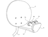
本発明の1実施形態のアンテナ回転装置を備えたディッシュアンテナは、図1に示すように、マルチビームアンテナであって、オフセットパラボラ反射鏡2と、この反射鏡2の焦点位置の近傍に設けられた複数、例えば3つの一次放射器4a、4b、4cを備えたローノイズブロックコンバータ6とを有している。これら一次放射器4a、4b、4cは、例えば赤道上空の所定の経度と緯度の位置にそれぞれ打ち上げられた3基の静止衛星、例えば放送衛星に対応して設けられている。
As shown in FIG. 1, the dish antenna including the antenna rotating device according to the embodiment of the present invention is a multi-beam antenna, and is provided near the offset
反射鏡2の背面側には、図3に示すように、回転角、仰角及び方位角調整装置8が配置されている。この調整装置8の下端から反射鏡2の正面側に伸びたアーム10にコンバータ6が取り付けられている。この回転角、仰角及び方位角調整装置8は、図1に示すようにマスト9に取り付けられている。
As shown in FIG. 3, a rotation angle, elevation angle, and azimuth angle adjusting device 8 is disposed on the back side of the reflecting
オフセットパラボラ反射鏡2は、3つの一次放射器4a、4b、4cの設置位置に、これら一次放射器4a、4b、4cに対応する電波が到来するように形成し、その中心軸が下端中央に位置するように所定の大きさにカットした形状を有している。この形状における開口面外形形状を図2に示す。即ち、上記形状の下端中央を原点として水平及び垂直方向にそれぞれ伸延する軸を、X及びY軸としたとき、開口面は、X及びYの値に従って下記のように表される。
The offset
X2+(Y−229.4)2=5302 (Xの絶対値≦59.2710mm、Y<229.4mm)
(X−34.1088)2+(Y−226.9132)2=2252 (59.2710mm<X≦258.9850mm、)
(X+34.1088)2+(Y−226.9132)2=2552 (−59.2710mm>X≧−258.9850mm、Y<229.4mm)
(X+40.85)2+(Y−229.4)2=3002 (254.4805mm≦X、Y>229.4mm)
(X−40.85)2+(Y−229.4)2=3002 (−254.4805mm≧X、Y>229.4mm)
(X−47.749)2+(Y−245.2175)2=2102 (79.0845mm≦X<249.4805、Y>229.4mm)
(X+47.749)2+(Y−245.2175)2=2102 (−79.0845mm≧X>−249.4805、Y>229.4mm)
X2+(Y+71.2)2=5302 (Xの絶対値≦79.0845mm、Y>229.4mm)
X 2 + (Y-229.4) 2 = 530 2 (absolute value of X ≦ 59.2710 mm, Y <229.4 mm)
(X-34.1088) 2 + (Y-226.9132) 2 = 225 2 (59.2710 mm <X ≦ 258.9850 mm)
(X + 34.1088) 2 + (Y-226.9132) 2 = 255 2 (−59.2710 mm> X ≧ −258.9850 mm, Y <229.4 mm)
(X + 40.85) 2 + (Y-229.4) 2 = 300 2 (2544.4805 mm ≦ X, Y> 229.4 mm)
(X-40.85) 2 + (Y-229.4) 2 = 300 2 (−254.4805 mm ≧ X, Y> 229.4 mm)
(X-47.749) 2 + (Y-245.2175) 2 = 210 2 (79.0845 mm ≦ X <249.4805, Y> 229.4 mm)
(X + 47.749) 2 + (Y-245.2175) 2 = 210 2 (−79.0845 mm ≧ X> −249.4805, Y> 229.4 mm)
X 2 + (Y + 71.2) 2 = 530 2 (absolute value of X ≦ 79.0845 mm, Y> 229.4 mm)
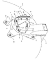
図3に示すように、このオフセットパラボラ反射鏡2の背面に、回転角、仰角及び方位角調整装置8のディッシュ用ブラケット12が着脱自在に取り付けられている。このディッシュ用ブラケット12は、平板部14を有している。平板部14は、図5に示すように、反射鏡2の背面から間隔を隔てて位置している。この平板部14は、反射鏡2の頂点(図2における原点)から、この反射鏡2の焦点に伸びた直線に平行で、ポラリティ軸16(図5参照)に垂直に位置している。この平板部14の下端が反射鏡2の下方にまで伸び、その下端にアーム10が取り付けられている。このブラケット12は、ボルト18によって反射鏡2に着脱自在に取り付けられている。
As shown in FIG. 3, the
上述したポラリティ軸16が通過する平板部14の点を中心として平板部14に所定の半径で描いた仮想円上に、複数、例えば3つの円弧溝20が、図4に示すように、形成されている。これら円弧溝20は、それぞれ同じ形状に形成され、それらの中心位置間がなす角度が等角度、例えば120度となるように形成されている。円弧溝20は平板部14の厚さ方向に貫通している。
As shown in FIG. 4, a plurality of, for example, three
上述した仮想円の中心から反射鏡2側に突出するように突起22が形成されている。そして、平板部14の反射鏡2側の面に接触するように、アダプタ板24が配置されている。このアダプタ板24は、例えば円板状に形成されている。このアダプタ板24の中心には、突起22が挿通される貫通孔25が形成されている。突起22が貫通孔25に挿通された状態において、ブラケット12及び反射鏡2がポラリティ軸16の回りに回転する。さらに、この貫通孔25を中心として上述した仮想円と同じ半径を持ってアダプタ板24上に描いた別の仮想円上に、複数、例えば3つの係合部、例えばネジ孔26が形成されている。これらネジ孔26は、各円弧溝20の中心位置間の角度と同じ角度、例えば120度をなすように形成されている。即ち、各ネジ孔26は、各円弧溝20に対応している。
A
回転角、仰角及び方位角調整装置8は、更に仰角用ブラケット28も有している。仰角用ブラケット28は、ブラケット12の背面側に設けられている。仰角用ブラケット28は、1対のウイング30、32を有している。これらウイング30、32は、同一形状の概略扇型に形成され、その直線状の一縁が平板部14に対して垂直にかつ所定の間隔を隔てて位置している。これらウイング30、32は、連結部34によって一体に結合されている。連結部34は、ウイング30、32に対して垂直に、且つ平板部14に対して垂直に、ウイング30、32の下部間に形成されている。
The rotation angle, elevation angle, and azimuth angle adjusting device 8 further includes an
ウイング30、32及び連結部34の平板部14に接触している縁部には、タブ36、38、40が形成されている。これらタブ36、38、40は、平板部14に接触するように、かつブラケット28の外方を向くように、ウイング30、32及び連結部34に対して垂直に形成されている。これらタブ36、38、40は、各円弧溝20上に重なるように位置している。これらタブ36、38、40には、挿通孔42、44、46が形成されている。これら挿通孔42、44、46は、各円弧溝20が位置する仮想円上に等角度、例えば120度間隔に位置するように、形成されている。
これら挿通孔42、44、46及び各円弧溝20を介して、各固定具、例えばボルト48が、アダプタ板24の各ネジ孔26に螺合している。これらボルト48の頭部はタブ36、38、40における反射鏡2とは反対側の面に位置している。各ボルト48を強固にネジ孔26に螺合させると、仰角用ブラケット28をディッシュ用ブラケット12の平板部14に固定することができる。しかし、各ボルト48を緩めた状態において、仰角用ブラケット28を固定していると、ディッシュ用ブラケット12及び反射鏡2をポラリティ軸16の回りに回転させることができる。図示していないが、1つの円弧溝に沿って角度目盛が形成されている。この角度目盛は、ポラリティ軸16の回りにブラケット12等を回転させる場合に使用される。
Each fixing tool, for example, a
ウイング30、32の要の部分には、それぞれボルト挿通孔50、52が形成されている。また、これらボルト挿通孔50、52を中心として、ウイング30、32の円弧状縁部に沿って円弧溝54、56が、それらの厚さ方向に貫通するように形成されている。
Bolt insertion holes 50 and 52 are formed in the main portions of the
回転角、仰角及び方位角調整装置8は、更に方位角用クランプ58も有している。この方位角用クランプ58は、ウイング30、32の間に配置されている。方位角用クランプ58は、図4に示すように、円筒状部60を有している。この円筒状部60にマスト9が挿通される。この円筒状部60の反射鏡2側の上部には、反射鏡2側に突出するようにタブ62、64が形成されている。これらタブ62、64には、ネジ孔66、68が形成され、これらネジ孔66、68には、ウイング30、32の要のボルト挿通孔50、52に挿通されたボルト70、72が挿通されている。仰角用ブラケット28は、これらボルト70、72の回りに回転自在である。従って、反射鏡2の仰角を調整可能である。円筒状部60の下端部の反射鏡2側にも、タブ74、76が形成されている。これらタブ74、76にもネジ孔78、80が形成されている。円弧溝54、56に挿通されたボルト82、84が、これらネジ孔78、80に螺合している。図示していないが、円弧溝54、56には、それにそって仰角調整用の目盛が形成されている。所定の仰角に対応する目盛の位置にボルト82、84が位置するように、ボルト70,72の回りに仰角用ブラケット28を回転させることによって、所定の仰角に反射鏡2を設定することができる。この設定後に、ボルト70、72、82、84が強固に締結される。
Rotation angle, elevation and azimuth adjusting device 8 also has
円筒状部60の反射鏡2から最も離れた部分は、円筒状部60の長さ方向に沿って切断されている。これら切断縁からさらに反射鏡2と反対側にタブ86、88が形成されている。これらタブ86には、その長さ方向に間隔をあけてネジ孔90、92が形成され、タブ88におけるネジ孔90、92に対応する位置に挿通孔94、96が形成されている。これら挿通孔94、96に挿通されたボルト98、100がネジ孔90、92に螺合して、マストに方位角用クランプ58を強固に固定する。従って、ボルト98、100を緩めた状態で、マストの回りに方位角用クランプ58を回転させて、反射鏡2に所定の方位角を向かせてから、ボルト98、100を強固に固定することによって、所定の方位角を向いた状態を維持することができる。
The portion of the
この回転角、仰角及び方位角調整装置8では、ディッシュ用ブラケット12の突起22にアダプタ24の貫通孔25を挿通し、各ネジ孔26が各円弧溝20上に位置するように、アダプタ24を回転させる。次に、仰角用ブラケット28のタブ36、38、40を、ディッシュ用ブラケット12の平板部14におけるアダプタ24とは反対側の面に配置し、各挿通孔42、44、46を各円弧溝20上に一致させる。各ボルト48を挿通孔42、44、46、円弧溝20、20、20を介してネジ孔26、26、26に緩く螺合させ、アダプタ24、ディッシュ用ブラケット12及び仰角用ブラケット28を結合させる。
The rotation angle, the elevation and azimuth adjusting device 8, inserted through the through
仰角用ブラケット28のウイング30、32の間に方位角用クランプ58を挿入し、ボルト70、72を挿通孔50、52に挿通してネジ孔66、68に緩く螺合させる。ボルト82、84を円弧溝54、56を介してネジ孔78、80に緩く螺合させる。
The
ボルト98、100を方位角用クランプ58の挿通孔94、96を介してネジ孔90、92に緩く螺合させる。
The
この状態で、回転角、仰角及び方位角調整装置8は、オフセットパラボラ反射鏡2と共に出荷される。
In this state, the rotation angle, elevation angle and azimuth angle adjusting device 8 is shipped together with the offset
オフセットパラボラアンテナの設置場所において、オフセットパラボラ反射鏡2への回転角、仰角及び方位角調整装置8の取付は、ディッシュ用ブラケット12をボルト18によって反射鏡2の背面に結合することによって開始される。次に、マスト9を方位角用クランプ58の円筒状部60に挿通する。そして、ディッシュ用ブラケット12及び反射鏡2を突起22の回りに所定の回転角となるように回転させ、各ボルト48を固定する。3つの一次放射器4a、4b、4cのうちいずれか、例えば一次放射器4aにおいて、対応する電波が良好に受信できるように、マスト9の回りに円筒状部60を回転させ、かつ、仰角用ブラケット28をボルト70、72の回りに回転させ、ボルト70、72、82、84、98、100を固定する。
At the place where the offset parabolic antenna is installed, the rotation angle, elevation angle and azimuth angle adjusting device 8 is attached to the offset
この回転角、仰角及び方位角調整装置8では、仰角用ブラケット28のウイング28、30は連結部34によって一体に形成されているので、ウイング28、30の位置関係は不変である。しかも、タブ36、38、40の挿通孔42、44、46は、回転アダプタ14の各ネジ孔26と一致しているので、ボルト70、72、82、84を緩めた状態で、各ボルト48を強固に固定しても、仰角用ブラケット28のディッシュ用ブラケット12に対する位置関係も不変である。また、仰角用ブラケット28のディッシュ用ブラケット12への取付は、仰角用ブラケット28側からボルト48をネジ孔26に螺合させるだけであるので、その作業が容易である。もし、アダプタ板24にネジ孔26ではなく、ボルト挿通孔が形成されているだけなら、これらボルト挿通孔の位置にナットを配置し、これらナットに各ボルト48を螺合させなければならず、その作業は非常に面倒である。
In the rotation angle, elevation angle and azimuth angle adjusting device 8, since the
上記の実施形態では、アダプタ板24には円板を使用したが、これに限ったものではなく、例えば矩形の板を使用することもできる。また、ネジ孔26、円弧溝20は、それぞれ3つずつ設けたが、これらの数は、それぞれ任意に変更することができる。
In the above embodiment, a circular plate is used as the
2 オフセットパラボラ反射鏡
8 回転角、仰角及び方位角調整装置
12 ディッシュ用ブラケット
14 平板部
16 ポラリティ軸
20 円弧溝
22 突起
22 貫通孔
24 アダプタ
25 ネジ孔(係合部)
28 仰角用ブラケット
30 32 ウイング
34 連結部
42 44 46 挿通孔
48 ボルト(固定具)
2 Offset parabolic reflector 8 Rotation angle, elevation angle, and azimuth
28 Bracket for
Claims (4)
前記平板における前記ディッシュアンテナ側の面に接触しているアダプタ板であって、前記ポラリティ軸を中心として前記アンテナ用ブラケットが前記アダプタ板に対して回転可能に構成され、前記各円弧溝に対応して複数の係合部が形成されている前記アダプタ板と、
前記平板における前記アンテナと反対側の面に配置された仰角用ブラケットであって、 前記平板に対してそれぞれが垂直であって、かつ互いに平行に位置する1対のウイングと、これら1対のウイングに対して垂直にかつ一体に形成された連結部とを、有し、前記1対のウイング間をこれらに垂直に通る仰角調整軸の回りに回転自在に形成され、前記平板に接触する前記円弧溝と同数のタブを有し、前記各タブは、前記1対のウイングの外方にそれぞれ突出し、前記各タブには、前記円弧溝に対応させて孔が形成されている仰角用ブラケットと、
前記仰角用ブラケット側から前記各孔及びこれらに対応する前記各円弧溝を通って、前記アダプタ板の前記係合部に係合して、前記仰角用ブラケット及び前記アンテナ用ブラケットを、前記アダプタ板に固定する複数の固定具とを、
具備するディッシュアンテナ回転装置。 A flat plate that can be attached to the rear surface of a dish antenna for a multi-beam antenna and that is perpendicular to the polarity axis when attached to the rear surface of the dish antenna. The flat plate is spaced from the rear surface of the dish antenna. And an antenna bracket having a plurality of arc grooves positioned at intervals on a virtual circumference drawn on the flat plate with the polarity axis as the center, and
An adapter plate in contact with the dish antenna side surface of the flat plate, wherein the antenna bracket is configured to be rotatable with respect to the adapter plate about the polarity axis, and corresponds to each arc groove. The adapter plate in which a plurality of engaging portions are formed,
A said antenna opposite elevation bracket disposed on a surface of the said flat plate, each of which is perpendicular to the flat plate, and a pair of wings located parallel to each other, these pair wings The arc that is formed to be rotatable about an elevation angle adjusting axis that passes perpendicularly to the pair of wings, and that contacts the flat plate. There are as many tabs as grooves, and each tab protrudes outward from the pair of wings, and each tab has an elevation angle bracket formed with a hole corresponding to the arc groove,
The elevation bracket and the antenna bracket are connected to the adapter plate by engaging with the engagement portion of the adapter plate through the holes and the arc grooves corresponding to the holes from the elevation bracket side. A plurality of fixtures to be fixed to
A dish antenna rotating apparatus provided.
Priority Applications (2)
| Application Number | Priority Date | Filing Date | Title |
|---|---|---|---|
| JP2003319524A JP4170863B2 (en) | 2003-09-11 | 2003-09-11 | Dish antenna rotating device |
| US10/684,698 US6864855B1 (en) | 2003-09-11 | 2003-10-14 | Dish antenna rotation apparatus |
Applications Claiming Priority (1)
| Application Number | Priority Date | Filing Date | Title |
|---|---|---|---|
| JP2003319524A JP4170863B2 (en) | 2003-09-11 | 2003-09-11 | Dish antenna rotating device |
Publications (3)
| Publication Number | Publication Date |
|---|---|
| JP2005086745A JP2005086745A (en) | 2005-03-31 |
| JP2005086745A5 JP2005086745A5 (en) | 2006-10-05 |
| JP4170863B2 true JP4170863B2 (en) | 2008-10-22 |
Family
ID=34214274
Family Applications (1)
| Application Number | Title | Priority Date | Filing Date |
|---|---|---|---|
| JP2003319524A Expired - Fee Related JP4170863B2 (en) | 2003-09-11 | 2003-09-11 | Dish antenna rotating device |
Country Status (2)
| Country | Link |
|---|---|
| US (1) | US6864855B1 (en) |
| JP (1) | JP4170863B2 (en) |
Families Citing this family (56)
| Publication number | Priority date | Publication date | Assignee | Title |
|---|---|---|---|---|
| US7954127B2 (en) | 2002-09-25 | 2011-05-31 | The Directv Group, Inc. | Direct broadcast signal distribution methods |
| US6963316B1 (en) * | 2004-06-22 | 2005-11-08 | Jonsa Technologies Co., Ltd. | Satellite antenna |
| US7173575B2 (en) * | 2005-01-26 | 2007-02-06 | Andrew Corporation | Reflector antenna support structure |
| US7900230B2 (en) | 2005-04-01 | 2011-03-01 | The Directv Group, Inc. | Intelligent two-way switching network |
| US7958531B2 (en) | 2005-04-01 | 2011-06-07 | The Directv Group, Inc. | Automatic level control for incoming signals of different signal strengths |
| US7987486B2 (en) | 2005-04-01 | 2011-07-26 | The Directv Group, Inc. | System architecture for control and signal distribution on coaxial cable |
| US8024759B2 (en) | 2005-04-01 | 2011-09-20 | The Directv Group, Inc. | Backwards-compatible frequency translation module for satellite video delivery |
| US7945932B2 (en) | 2005-04-01 | 2011-05-17 | The Directv Group, Inc. | Narrow bandwidth signal delivery system |
| US7950038B2 (en) * | 2005-04-01 | 2011-05-24 | The Directv Group, Inc. | Transponder tuning and mapping |
| TWM293540U (en) * | 2005-08-31 | 2006-07-01 | Wistron Neweb Corp | The fine tuning mechanism of the satellite antenna |
| US7937732B2 (en) | 2005-09-02 | 2011-05-03 | The Directv Group, Inc. | Network fraud prevention via registration and verification |
| US8789115B2 (en) * | 2005-09-02 | 2014-07-22 | The Directv Group, Inc. | Frequency translation module discovery and configuration |
| US20080016535A1 (en) * | 2005-09-02 | 2008-01-17 | The Directv Group, Inc. | Frequency shift key control in video delivery systems |
| US7991348B2 (en) * | 2005-10-12 | 2011-08-02 | The Directv Group, Inc. | Triple band combining approach to satellite signal distribution |
| US8019275B2 (en) * | 2005-10-12 | 2011-09-13 | The Directv Group, Inc. | Band upconverter approach to KA/KU signal distribution |
| US8515342B2 (en) * | 2005-10-12 | 2013-08-20 | The Directv Group, Inc. | Dynamic current sharing in KA/KU LNB design |
| US7636067B2 (en) * | 2005-10-12 | 2009-12-22 | The Directv Group, Inc. | Ka/Ku antenna alignment |
| US7609218B2 (en) * | 2005-10-12 | 2009-10-27 | The Directv Group, Inc. | Enhanced back assembly for Ka/Ku ODU |
| US20070080887A1 (en) * | 2005-10-12 | 2007-04-12 | Kesse Ho | KA LNB umbrella shade |
| US7663543B2 (en) * | 2005-10-12 | 2010-02-16 | The Directv Group, Inc. | Alignment method for multi-satellite consumer receiver antennas |
| US9282299B2 (en) * | 2005-10-12 | 2016-03-08 | The Directv Group, Inc. | Single local oscillator sharing in multi-band Ka-band LNBS |
| US20070089142A1 (en) * | 2005-10-14 | 2007-04-19 | John Norin | Band converter approach to Ka/Ku signal distribution |
| TWI295864B (en) * | 2006-01-27 | 2008-04-11 | Wistron Neweb Corp | Antenna and supporting structure and elevation angle adjusting method thereof |
| US7385564B2 (en) * | 2006-03-10 | 2008-06-10 | Winegard Company | Satellite dish antenna mounting system |
| TWI306681B (en) * | 2006-04-20 | 2009-02-21 | Wistron Neweb Corp | Antenna and supporting structure |
| TW200742891A (en) * | 2006-05-11 | 2007-11-16 | Benq Corp | Display and assembly structure |
| EP2033442A2 (en) * | 2006-06-09 | 2009-03-11 | The DIRECTV Group, Inc. | Presentation modes for various format bit streams |
| WO2007149403A2 (en) * | 2006-06-16 | 2007-12-27 | The Directv Group, Inc. | Digital storage media command and control data indexing |
| US7411562B2 (en) * | 2006-10-19 | 2008-08-12 | Ming-Tien Lin | Apparatus for supporting a satellite antenna dish and a satellite receiver |
| US8719875B2 (en) | 2006-11-06 | 2014-05-06 | The Directv Group, Inc. | Satellite television IP bitstream generator receiving unit |
| US8712318B2 (en) | 2007-05-29 | 2014-04-29 | The Directv Group, Inc. | Integrated multi-sat LNB and frequency translation module |
| US8238813B1 (en) | 2007-08-20 | 2012-08-07 | The Directv Group, Inc. | Computationally efficient design for broadcast satellite single wire and/or direct demod interface |
| US9942618B2 (en) * | 2007-10-31 | 2018-04-10 | The Directv Group, Inc. | SMATV headend using IP transport stream input and method for operating the same |
| WO2010080823A1 (en) | 2009-01-06 | 2010-07-15 | The Directv Group, Inc. | Frequency drift estimation for low cost outdoor unit |
| US20100224750A1 (en) * | 2009-03-04 | 2010-09-09 | Nimrod Webber | Loudspeaker tilting adapter |
| US8558734B1 (en) * | 2009-07-22 | 2013-10-15 | Gregory Hubert Piesinger | Three dimensional radar antenna method and apparatus |
| US8020824B2 (en) * | 2009-08-04 | 2011-09-20 | Jonsa Technologies Co., Ltd. | Adjustment assembly for a satellite antenna |
| US8416147B2 (en) * | 2009-12-16 | 2013-04-09 | EchoStar Technologies, L.L.C. | Systems, methods and apparatus for mounting an object to a structure |
| US8251325B2 (en) | 2010-06-01 | 2012-08-28 | Peerless Industries, Inc. | Adjustable display bracket |
| TWI443265B (en) * | 2011-02-22 | 2014-07-01 | Wistron Neweb Corp | Clamp structure capable of preventing a plank thereof from bending |
| CN102642185B (en) * | 2011-02-22 | 2015-04-15 | 启碁科技股份有限公司 | Clamp structure with function of preventing plate parts from being bent |
| TWI394641B (en) * | 2011-02-23 | 2013-05-01 | Wistron Neweb Corp | Clamp structure |
| TWI449260B (en) * | 2011-02-23 | 2014-08-11 | Wistron Neweb Corp | Adjusting mechanism for adjusting rotation angle and antenna system therewith |
| US20120211632A1 (en) * | 2011-02-23 | 2012-08-23 | Lan-Chun Yang | Supporting pedestal and related antenna system |
| US20120211634A1 (en) * | 2011-02-23 | 2012-08-23 | Lan-Chun Yang | Supporting pedestal and related antenna system |
| CN102651494B (en) * | 2011-02-24 | 2014-11-05 | 启碁科技股份有限公司 | Clamp structure |
| US20130048811A1 (en) * | 2011-08-30 | 2013-02-28 | Yi-Chen Tseng | A mounting kit |
| TW201325974A (en) * | 2011-09-07 | 2013-07-01 | Kempter Marketing Inc | Unified universal rack connector |
| TWI497812B (en) * | 2011-11-29 | 2015-08-21 | Wistron Neweb Corp | Adjusting mechanism and related antenna system |
| CN104191394B (en) * | 2014-09-01 | 2016-01-06 | 北京航空航天大学 | The anti-bending fixture of a kind of single-ride joint |
| US9660320B2 (en) | 2015-06-10 | 2017-05-23 | Highlands Diversified Services, Inc. | High efficiency mounting assembly for satellite dish reflector |
| WO2017052384A1 (en) * | 2015-09-21 | 2017-03-30 | Tru-Test Limited | Insulator |
| CN105914467B (en) * | 2016-06-08 | 2019-07-09 | 京信通信技术(广州)有限公司 | Antenna turning unit and antenna |
| US10038238B2 (en) * | 2016-06-30 | 2018-07-31 | Nokia Shanghai Bell Co., Ltd. | Load-resistant antenna mount |
| WO2019241870A1 (en) * | 2018-11-20 | 2019-12-26 | Gestion Logiscasa Inc. | Basketball hoop pole holder |
| USD951762S1 (en) * | 2020-11-25 | 2022-05-17 | Mafi Ab | Fastening device |
Family Cites Families (5)
| Publication number | Priority date | Publication date | Assignee | Title |
|---|---|---|---|---|
| US5526010A (en) * | 1995-02-09 | 1996-06-11 | Plunk; Richard L. | Support device for portable satellite dish |
| JP3242857B2 (en) * | 1997-03-13 | 2001-12-25 | デイエツクスアンテナ株式会社 | Antenna mounting |
| US6188372B1 (en) * | 1999-06-17 | 2001-02-13 | Channel Master Llc | Antenna with molded integral polarity plate |
| TW465812U (en) * | 2000-05-29 | 2001-11-21 | Acer Neweb Corp | Rotation device of disc-shape antenna |
| US6762731B1 (en) * | 2003-01-28 | 2004-07-13 | Microelectronics Technology Inc. | Dish antenna rotation apparatus |
-
2003
- 2003-09-11 JP JP2003319524A patent/JP4170863B2/en not_active Expired - Fee Related
- 2003-10-14 US US10/684,698 patent/US6864855B1/en not_active Expired - Fee Related
Also Published As
| Publication number | Publication date |
|---|---|
| JP2005086745A (en) | 2005-03-31 |
| US20050057428A1 (en) | 2005-03-17 |
| US6864855B1 (en) | 2005-03-08 |
Similar Documents
| Publication | Publication Date | Title |
|---|---|---|
| JP4170863B2 (en) | Dish antenna rotating device | |
| US11631929B2 (en) | Fastening device and associated method | |
| EP1050925B1 (en) | Multi-primary radiator, down converter and multibeam antenna | |
| JP5147800B2 (en) | Antenna support device | |
| WO2013008932A1 (en) | Antenna support device | |
| JP2002204111A (en) | Multi-beam parabolic antenna rotation angle regulating adapter | |
| JP2588660B2 (en) | Mounting structure of outdoor transceiver for antenna | |
| JP2649096B2 (en) | Method of receiving radio waves from geostationary satellites and parabolic antenna used therefor | |
| JP2531780Y2 (en) | Primary radiator support device | |
| JPH07226621A (en) | Offset parabolic antenna polarization plane adjustment mechanism | |
| JPS646571Y2 (en) | ||
| JP3300860B2 (en) | Antenna device and receiving method | |
| RU2004113095A (en) | LENS ANTENNA DEVICE | |
| JPS6342728Y2 (en) | ||
| JP3174808B2 (en) | Feed horn mounting | |
| JP3634150B2 (en) | parabolic antenna | |
| JP2002009517A (en) | Antenna mount structure | |
| JPH11234011A (en) | Antenna fixture | |
| JP2008271003A (en) | Radio-wave lens antenna device | |
| JPH0685514U (en) | Supporting device for primary radiator | |
| JPS6338567Y2 (en) | ||
| JP2567916Y2 (en) | Dual beam antenna | |
| JPS6342727Y2 (en) | ||
| JP3250081B2 (en) | Antenna support device | |
| JP3250080B2 (en) | Antenna support device |
Legal Events
| Date | Code | Title | Description |
|---|---|---|---|
| A521 | Written amendment |
Free format text: JAPANESE INTERMEDIATE CODE: A523 Effective date: 20060823 |
|
| A621 | Written request for application examination |
Free format text: JAPANESE INTERMEDIATE CODE: A621 Effective date: 20060823 |
|
| A131 | Notification of reasons for refusal |
Free format text: JAPANESE INTERMEDIATE CODE: A131 Effective date: 20080430 |
|
| A521 | Written amendment |
Free format text: JAPANESE INTERMEDIATE CODE: A523 Effective date: 20080630 |
|
| TRDD | Decision of grant or rejection written | ||
| A01 | Written decision to grant a patent or to grant a registration (utility model) |
Free format text: JAPANESE INTERMEDIATE CODE: A01 Effective date: 20080805 |
|
| A01 | Written decision to grant a patent or to grant a registration (utility model) |
Free format text: JAPANESE INTERMEDIATE CODE: A01 |
|
| A61 | First payment of annual fees (during grant procedure) |
Free format text: JAPANESE INTERMEDIATE CODE: A61 Effective date: 20080807 |
|
| FPAY | Renewal fee payment (event date is renewal date of database) |
Free format text: PAYMENT UNTIL: 20110815 Year of fee payment: 3 |
|
| R150 | Certificate of patent or registration of utility model |
Free format text: JAPANESE INTERMEDIATE CODE: R150 |
|
| FPAY | Renewal fee payment (event date is renewal date of database) |
Free format text: PAYMENT UNTIL: 20110815 Year of fee payment: 3 |
|
| FPAY | Renewal fee payment (event date is renewal date of database) |
Free format text: PAYMENT UNTIL: 20120815 Year of fee payment: 4 |
|
| LAPS | Cancellation because of no payment of annual fees |