US10219652B2 - Portable stove - Google Patents
Portable stove Download PDFInfo
- Publication number
- US10219652B2 US10219652B2 US14/703,765 US201514703765A US10219652B2 US 10219652 B2 US10219652 B2 US 10219652B2 US 201514703765 A US201514703765 A US 201514703765A US 10219652 B2 US10219652 B2 US 10219652B2
- Authority
- US
- United States
- Prior art keywords
- portable stove
- burner head
- flame spreader
- jet
- elastic element
- Prior art date
- Legal status (The legal status is an assumption and is not a legal conclusion. Google has not performed a legal analysis and makes no representation as to the accuracy of the status listed.)
- Active, expires
Links
Images


Classifications
-
- A—HUMAN NECESSITIES
- A47—FURNITURE; DOMESTIC ARTICLES OR APPLIANCES; COFFEE MILLS; SPICE MILLS; SUCTION CLEANERS IN GENERAL
- A47J—KITCHEN EQUIPMENT; COFFEE MILLS; SPICE MILLS; APPARATUS FOR MAKING BEVERAGES
- A47J37/00—Baking; Roasting; Grilling; Frying
- A47J37/06—Roasters; Grills; Sandwich grills
- A47J37/07—Roasting devices for outdoor use; Barbecues
- A47J37/0763—Small-size, portable barbecues
-
- A—HUMAN NECESSITIES
- A47—FURNITURE; DOMESTIC ARTICLES OR APPLIANCES; COFFEE MILLS; SPICE MILLS; SUCTION CLEANERS IN GENERAL
- A47J—KITCHEN EQUIPMENT; COFFEE MILLS; SPICE MILLS; APPARATUS FOR MAKING BEVERAGES
- A47J37/00—Baking; Roasting; Grilling; Frying
- A47J37/06—Roasters; Grills; Sandwich grills
- A47J37/0623—Small-size cooking ovens, i.e. defining an at least partially closed cooking cavity
- A47J37/0647—Small-size cooking ovens, i.e. defining an at least partially closed cooking cavity with gas burners
-
- A—HUMAN NECESSITIES
- A47—FURNITURE; DOMESTIC ARTICLES OR APPLIANCES; COFFEE MILLS; SPICE MILLS; SUCTION CLEANERS IN GENERAL
- A47J—KITCHEN EQUIPMENT; COFFEE MILLS; SPICE MILLS; APPARATUS FOR MAKING BEVERAGES
- A47J37/00—Baking; Roasting; Grilling; Frying
- A47J37/06—Roasters; Grills; Sandwich grills
- A47J37/07—Roasting devices for outdoor use; Barbecues
- A47J37/0704—Roasting devices for outdoor use; Barbecues with horizontal fire box
- A47J37/0713—Roasting devices for outdoor use; Barbecues with horizontal fire box with gas burners
-
- F—MECHANICAL ENGINEERING; LIGHTING; HEATING; WEAPONS; BLASTING
- F24—HEATING; RANGES; VENTILATING
- F24C—DOMESTIC STOVES OR RANGES ; DETAILS OF DOMESTIC STOVES OR RANGES, OF GENERAL APPLICATION
- F24C3/00—Stoves or ranges for gaseous fuels
- F24C3/14—Stoves or ranges for gaseous fuels with special adaptation for travelling, e.g. collapsible
Definitions
- the present invention relates to a portable stove.
- the present invention relates to a portable stove for burning multiple fuels.
- such portable stoves comprise a burner body having a burner head, an exchangeable jet screwable into the burner head, a plurality of legs attached to the burner body, and a flame spreader detachably mounted on top of the burner head upstream the jet in the flame direction.
- the flame emerges from the jet and hits the flame spreader where the flame is laterally distributed to obtain a planar heating of the cookware placed on top of the burner head.
- the legs are intended to have the portable stove stably resting on a surface or ground floor and can for instance be plugged to the burner body or be pivotally mounted to the burner body.
- a portable stove as describe above is available as Primus® OmniFuel Stove.
- Said stove can be used with a plurality of different combustibles including gaseous combustibles like propane, butane or a mixture thereof, white gas, or liquid combustibles like vehicle petrol, kerosene or diesel oil.
- gaseous combustibles like propane, butane or a mixture thereof
- white gas or liquid combustibles like vehicle petrol, kerosene or diesel oil.
- liquid combustibles like vehicle petrol, kerosene or diesel oil.
- FIG. 1 A schematic perspective view of the Primus® OmniFuel Stove is shown in FIG. 1 with the portable stove being connected to a gas cartridge storing a gaseous combustible ( FIG. 1 a ) and being connected to a fuel bottle storing liquid combustible (cf. FIG. 1 b ).
- the jet mounted to the burner head has to be chosen to suit the combustible used. For instance, in case liquid fuel is used, a jet having a smaller size is to be mounted to the burner head compared to the jet to be used when a gaseous combustible is burned.
- the flame spreader is detached from the burner head, and the jet currently mounted to the burner head is unscrewed. Afterwards the new jet is screwed to the burner head and the flame spreader is again mounted.
- the latter one is provided with three mounting arms having catch mechanisms at the ends which engage the upper rim of the burner head.
- the catch mechanisms may be worn if mounted and demounted many a time. Thus, the flame spread might no longer be stably fitted to the stove or might even get lost during travelling.
- the inventive portable stove as described in claim 1 is characterized in that the portable stove comprises at least a second exchangeable jet screwable into the burner head, and the portable stove further comprises at least one mounting structure, wherein the second jet is supported within said mounting structure.
- the non-used jet can be stored together with the portable stove.
- the non-used jets are no longer stored in a separate storage container, but are directly fitted to the portable stove. Hence, the jets cannot be lost.
- the mounting structure is disposed on one of said legs.
- the mounting structure can be provided on one leg or on any number of legs depending on the amount of jets to be carried together with the portable stove.
- the mounting structure is an opening having an inside thread, wherein the second jet is screwed into the opening.
- the external thread provided on the jet for screwing it into the burner head further allows the jet to be screwed into the opening such that the jet is secured to the portable stove.
- the mounting structure may also be provided as a structure having an external threading in case the jets are provided with an internal threading.
- the flame spreader is attached to the portable stove with an elastic element.
- the elastic element provides a force sufficiently high to securely fix the flame spreader to the burner head. This in turn facilitates the mounting and demounting of the flame spreader, and further prevents wearing of the flame spreader.
- the flame spreader comprises a baffle plate and at least two mounting arms extending from the baffle plate.
- a first mounting arm is attachable to the burner head by a form-fit, and wherein a second mounting arm is attached to a first end of the elastic element.
- the flame spreader is attached to the burner head in that the form fit is established by catching the burner head with the respective catch mechanism provided at the end of the first mounting arm, wherein the force generated by the elastic element secures the flame spreader on the burner head.
- This arrangement greatly facilitates the mounting and demounting procedure of the flame spreader and further inhibits wearing as the mounting arms do not need to be elastically deformed for mounting and demounting the burner head.
- the flame spreader may comprise more than two mounting arms with at least two mounting arms being attachable to the burner head by a form-fit.
- a second end of the elastic element is attached to the burner body. This allows the flame spreader to be easily mounted to and demounted from the burner head. In addition, the elastic element can be easily accessed and replaced if necessary.
- the burner body comprises a wind shield surrounding the burner head, wherein the second end of the elastic element is attached to the wind shield.
- the wind shield ameliorates the flame pattern and inhibits a distorted heat transfer caused by wind.
- the wind shield comprises a clearance on its upper end, wherein the second mounting arm is rests in the clearance when the flame spreader is mounted to the burner head.
- This facilitates the mounting of the flame spreader as only one possibility of mounting the flame spreader is possible.
- the second mounting arm cannot be laterally displaced which in turn inhibits the unintended separation of the flame spreader and the burner head.
- the elastic element is an elastic tension element, preferably a helical tension spring.
- Helical tension springs are commonly available and thus, are inexpensive and can easily be replaced if out of function.
- one of said jets is suitable for gaseous combustibles and wherein one of said jets is suitable for liquid combustibles.
- the portable stove can be used e.g. to prepare food or heat up water independently from the combustible available. This allows the portable stove to be used under a wide range of conditions.
- the portable stove further comprises a multitool for screwing and unscrewing the jets into the burner head.
- the jets can be screwed to the burner head with a sufficient load.
- a sufficient load is mandatory to allow the portable stove to be operated adequately.
- the multitool can be secured to the portable stove when the portable stove is stored and not in use.
- FIG. 1 a is a perspective view of a prior art portable stove
- FIG. 1 b is a perspective view of a prior art portable stove
- FIG. 2 is a perspective view of the portable stove with mounted flame spreader
- FIG. 3 is a perspective view of the portable stove with demounted flame spreader
- FIG. 4 is a top view of the portable stove with demounted flame spreader
- FIG. 5 is a detail view of a leg of the portable stove
- FIG. 6 is a detail view of a leg of the portable stove with mounted jets
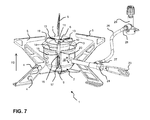
- FIG. 7 is a perspective view of the portable stove.
- FIG. 8 is a perspective view of the portable stove with a multitool.
- the portable stove 1 is a multifuel portable stove 1 . Hence, it can be used with a variety of different combustibles.
- the portable stove 1 comprises a burner body 2 having a burner head 3 disposed within the burner body 2 .
- a jet 4 is screwed into the burner head 3 and a plurality of legs 5 are attached to the burner body 2 . In the embodiment shown, three legs 5 are attached to the burner body 2 in a hinged manner.
- a flame spreader 6 is mounted on top of the burner head 3 upstream of the jet 4 in the flame direction FD.
- the portable stove 1 further comprises a wind shield 18 surrounding the burner head 3 and a gas control 23 mounted within an inlet tube 24 for regulation of the combustible flow.
- the inlet tube 24 comprises a connection valve 25 and further opens out into the burner head 3 .
- a first end 27 of a hose 26 is attached to the connection valve 25 and a second end 28 of the hose 26 is connected to a shut-off valve 29 which can either be directly mounted to a cartridge 21 containing gaseous combustible (as shown in FIG. 1 a for a prior art stove) or to a pumping device 30 , the latter one being connected to a fuel bottle 22 containing liquid combustible (as shown in. FIG. 1 b for a prior art stove).
- the flame spreader 6 comprises a baffle plate 10 and three mounting arms 11 , 13 extending from the baffle plate 10 in the radial direction. Two of the mounting arms 13 are provided with catch mechanisms 12 at its ends which can be engaged to an upper rim portion 7 of the burner head 3 , as can be seen from e.g. FIG. 3 .
- One mounting arm 11 is provided with a substantially perpendicular extending arm portion 14 at its end. When mounted to the burner head 3 , the arm portion 14 extends virtually parallel to the burner head 3 and has a mounting section 15 at its end.
- the elastic element 9 is composed of a helical tension spring 9 which is mounted to the mounting section 15 with its first spring end 16 .
- the second spring end 17 is attached to the burner body 2 , in the embodiment shown to the wind shield 18 .
- the wind shield 18 is provided with a clearance 20 at its upper end rim portion 19 and the mounting arm 11 with the arm portion 14 is resting within the clearance 20 when the flame spreader 6 is mounted to the burner head 3 (cf. FIG. 2 ).
- the flame spreader 6 is manually moved over the burner head 3 , therewith stretching the helical tension spring 9 such that a force is generated. Then, the two mounting arms 13 with the catch mechanisms 12 are attached to the burner head 3 such that a form-fit is established between the catch mechanisms 12 and the upper rim 7 of the burner head 3 . Next, the flame spreader 6 is lowered until the mounting arms 13 are supported on the upper rim 7 of the burner head 3 . As the helical tension spring 9 is not stress-free, but still expanded to some degree, the flame spreader 6 is pressed onto the burner head 3 and cannot separate therefrom. Unintended separation of the flame spreader 6 and the burner head 3 is further hindered as the mounting arm 11 with the arm portion 14 rests within the clearance 20 and lateral displacement thereof is inhibited.
- the above described procedure is reversed, i.e. the flame spreader 6 is manually lifted from the burner head 3 against the spring force and the catch mechanisms 12 are then disengaged from the upper rim 7 of the burner head 3 .
- the helical tension spring 9 is permanently attached to the wind shield 18 with its second spring end 17 and to the flame spreader 6 with its first spring end 16 , the flame spreader 6 cannot get lost when demounted.
- the portable stove 1 comprises a multitool 31 which can be brought into engagement with the mounted jet 4 .
- the jet 4 is unscrewed from the burner head 3 and can be removed.
- one of the legs 5 of the portable stove 1 comprises two mounting structures 8 in form of openings 8 with inner threads.
- the jet 4 can be screwed into one of the openings 8 (cf. FIG. 6 ) such that it is securely fixed to the portable stove 1 .
- a second jet 4 which is now to be screwed into the burner head 3 can be unscrewed from the leg 5 .
- three jets 4 are provided for the different combustibles used, namely one of the size 0.45 mm for cartridge gas (e.g. propane/butane mixture), one of the size 0.37 mm for white gas and one of the size 0.28 mm for liquid combustibles.
- two of the jets 4 are screwed into the respective opening 8 provided at one of the legs 5 of the portable stove 1 , wherein one of the jets 4 is screwed to the burner head 3 , the latter one being the one in use.
Abstract
Description
Claims (9)
Applications Claiming Priority (3)
| Application Number | Priority Date | Filing Date | Title |
|---|---|---|---|
| EP14166975.4 | 2014-05-05 | ||
| EP14166975.4A EP2942566A1 (en) | 2014-05-05 | 2014-05-05 | Portable stove |
| EP14166975 | 2014-05-05 |
Publications (2)
| Publication Number | Publication Date |
|---|---|
| US20150313409A1 US20150313409A1 (en) | 2015-11-05 |
| US10219652B2 true US10219652B2 (en) | 2019-03-05 |
Family
ID=50628695
Family Applications (1)
| Application Number | Title | Priority Date | Filing Date |
|---|---|---|---|
| US14/703,765 Active 2036-01-24 US10219652B2 (en) | 2014-05-05 | 2015-05-04 | Portable stove |
Country Status (2)
| Country | Link |
|---|---|
| US (1) | US10219652B2 (en) |
| EP (1) | EP2942566A1 (en) |
Families Citing this family (2)
| Publication number | Priority date | Publication date | Assignee | Title |
|---|---|---|---|---|
| EP2942566A1 (en) * | 2014-05-05 | 2015-11-11 | Fenix Outdoor AB | Portable stove |
| USD911092S1 (en) * | 2019-01-25 | 2021-02-23 | Jianming Zhang | Outdoor stove |
Citations (39)
| Publication number | Priority date | Publication date | Assignee | Title |
|---|---|---|---|---|
| US3289731A (en) * | 1963-08-05 | 1966-12-06 | Sievert Ab Max | Burner for gaseous fuel |
| US3703166A (en) * | 1971-07-08 | 1972-11-21 | Colorado Technologists Inc | Liquid fuel cooking stove |
| US3829278A (en) * | 1973-04-20 | 1974-08-13 | Penberthy Harvey Larry | Gasoline stove |
| US4092974A (en) * | 1976-07-12 | 1978-06-06 | International Business Development Company | Pocket camp stove |
| US4105013A (en) * | 1975-09-23 | 1978-08-08 | Application Des Gaz | Portable stoves |
| US4177790A (en) * | 1976-07-12 | 1979-12-11 | International Business Development Co. | Pocket camp stove |
| US4604049A (en) * | 1985-08-26 | 1986-08-05 | Robertshaw Controls Company | Dual rate burner construction and method of making the same |
| US5613485A (en) * | 1995-01-30 | 1997-03-25 | Coleman Taymar Limited | Campstove with adjustable grate |
| US5803727A (en) * | 1997-01-30 | 1998-09-08 | The Coleman Company, Inc. | Burner assembly for burning appliances |
| US5868126A (en) * | 1996-08-12 | 1999-02-09 | The Coleman Company, Inc. | LPG canister connector for combustion appliance |
| US5954044A (en) * | 1996-08-12 | 1999-09-21 | The Coleman Company Inc. | Connector for securing a conduit to a fluid source |
| US5979428A (en) * | 1998-12-31 | 1999-11-09 | Greene, Jr.; George J. | Wind guard attachment for portable gas cookers |
| USD416750S (en) * | 1997-07-14 | 1999-11-23 | Primus Ab | Open air stove |
| US6173709B1 (en) * | 1999-09-17 | 2001-01-16 | Snow Peak, Inc. | Portable gas cooking stove |
| US6182651B1 (en) * | 1997-07-14 | 2001-02-06 | Primus Ab | Open air stove |
| US6213760B1 (en) * | 1999-01-08 | 2001-04-10 | Snow Peak, Inc. | Burner for portable gas cooking stove |
| US6237891B1 (en) * | 1999-09-08 | 2001-05-29 | Burnswick Corporation | Adaptor for use of alternate gas fuel |
| USD446991S1 (en) * | 1997-10-14 | 2001-08-28 | Iwatani Sangyo Kabushiki Kaisha | Portable gas burner |
| US20040200436A1 (en) * | 2003-02-24 | 2004-10-14 | Staack Lavra A Saylor | Spring tether |
| US7137810B2 (en) * | 2001-09-06 | 2006-11-21 | Primus Ab | Piezo ignition device |
| US20070006868A1 (en) * | 2005-07-08 | 2007-01-11 | Joel Svedlund | Outdoor stove burner control |
| US7168426B1 (en) * | 2005-07-20 | 2007-01-30 | Huang-Hsi Hsu | Portable gas stove assembly |
| USD542908S1 (en) * | 2005-06-14 | 2007-05-15 | Primus Ab | Outdoor stove |
| US20080029082A1 (en) * | 2006-08-04 | 2008-02-07 | Dowst W Perry | Interchangeable system for high-efficiency heating and cooking |
| US20080184981A1 (en) * | 2007-02-06 | 2008-08-07 | Albert Su | Multi-Function Portable Gas Stove |
| US7553264B2 (en) * | 2007-05-18 | 2009-06-30 | Tuffstuff Fitness Equipment, Inc. | Push/pull exercise apparatus, device, and method |
| US20090280447A1 (en) * | 2006-08-04 | 2009-11-12 | The Coleman Company, Inc. | Backpacking stove |
| USD610390S1 (en) * | 2009-01-21 | 2010-02-23 | Shinfuji Burner Co., Ltd. | Portable gas cooking stove |
| US7775203B1 (en) * | 2006-05-08 | 2010-08-17 | Jerry Dale Patrick | Stand assembly for supporting free-standing objects |
| US7896266B1 (en) * | 2008-12-16 | 2011-03-01 | Cooper Martin L | Wheeled attachment for pressure washer |
| US8459247B1 (en) * | 2006-06-01 | 2013-06-11 | Barbara Bourgeois | Outdoor cooking apparatus with removable heat shield |
| USD683999S1 (en) * | 2011-06-24 | 2013-06-11 | Primus Ab | Portable stove |
| US8650731B2 (en) * | 2010-02-26 | 2014-02-18 | Karat Industrial Corporation | Rivet tool capable of measuring size of blind rivet |
| US8695582B1 (en) * | 2012-11-26 | 2014-04-15 | Lava Outdoor Appliance Co., Ltd. | Supporting assembly for portable stove |
| US8776338B2 (en) * | 2010-11-20 | 2014-07-15 | Jianming Yuan | Single handle pulling riveting gun |
| US20150313409A1 (en) * | 2014-05-05 | 2015-11-05 | Fenix Outdoor Development and CSR AG | Portable stove |
| US9383111B2 (en) * | 2013-06-03 | 2016-07-05 | Adam Royce Nelson, SR. | Propane swivel burner |
| US9429327B2 (en) * | 2013-03-26 | 2016-08-30 | Kovea Co., Ltd. | Hose burner |
| US9795251B2 (en) * | 2015-06-24 | 2017-10-24 | Joshua Rosecrans | Detachable external heating device for an outdoor grill or smoker |
-
2014
- 2014-05-05 EP EP14166975.4A patent/EP2942566A1/en not_active Withdrawn
-
2015
- 2015-05-04 US US14/703,765 patent/US10219652B2/en active Active
Patent Citations (39)
| Publication number | Priority date | Publication date | Assignee | Title |
|---|---|---|---|---|
| US3289731A (en) * | 1963-08-05 | 1966-12-06 | Sievert Ab Max | Burner for gaseous fuel |
| US3703166A (en) * | 1971-07-08 | 1972-11-21 | Colorado Technologists Inc | Liquid fuel cooking stove |
| US3829278A (en) * | 1973-04-20 | 1974-08-13 | Penberthy Harvey Larry | Gasoline stove |
| US4105013A (en) * | 1975-09-23 | 1978-08-08 | Application Des Gaz | Portable stoves |
| US4092974A (en) * | 1976-07-12 | 1978-06-06 | International Business Development Company | Pocket camp stove |
| US4177790A (en) * | 1976-07-12 | 1979-12-11 | International Business Development Co. | Pocket camp stove |
| US4604049A (en) * | 1985-08-26 | 1986-08-05 | Robertshaw Controls Company | Dual rate burner construction and method of making the same |
| US5613485A (en) * | 1995-01-30 | 1997-03-25 | Coleman Taymar Limited | Campstove with adjustable grate |
| US5954044A (en) * | 1996-08-12 | 1999-09-21 | The Coleman Company Inc. | Connector for securing a conduit to a fluid source |
| US5868126A (en) * | 1996-08-12 | 1999-02-09 | The Coleman Company, Inc. | LPG canister connector for combustion appliance |
| US5803727A (en) * | 1997-01-30 | 1998-09-08 | The Coleman Company, Inc. | Burner assembly for burning appliances |
| USD416750S (en) * | 1997-07-14 | 1999-11-23 | Primus Ab | Open air stove |
| US6182651B1 (en) * | 1997-07-14 | 2001-02-06 | Primus Ab | Open air stove |
| USD446991S1 (en) * | 1997-10-14 | 2001-08-28 | Iwatani Sangyo Kabushiki Kaisha | Portable gas burner |
| US5979428A (en) * | 1998-12-31 | 1999-11-09 | Greene, Jr.; George J. | Wind guard attachment for portable gas cookers |
| US6213760B1 (en) * | 1999-01-08 | 2001-04-10 | Snow Peak, Inc. | Burner for portable gas cooking stove |
| US6237891B1 (en) * | 1999-09-08 | 2001-05-29 | Burnswick Corporation | Adaptor for use of alternate gas fuel |
| US6173709B1 (en) * | 1999-09-17 | 2001-01-16 | Snow Peak, Inc. | Portable gas cooking stove |
| US7137810B2 (en) * | 2001-09-06 | 2006-11-21 | Primus Ab | Piezo ignition device |
| US20040200436A1 (en) * | 2003-02-24 | 2004-10-14 | Staack Lavra A Saylor | Spring tether |
| USD542908S1 (en) * | 2005-06-14 | 2007-05-15 | Primus Ab | Outdoor stove |
| US20070006868A1 (en) * | 2005-07-08 | 2007-01-11 | Joel Svedlund | Outdoor stove burner control |
| US7168426B1 (en) * | 2005-07-20 | 2007-01-30 | Huang-Hsi Hsu | Portable gas stove assembly |
| US7775203B1 (en) * | 2006-05-08 | 2010-08-17 | Jerry Dale Patrick | Stand assembly for supporting free-standing objects |
| US8459247B1 (en) * | 2006-06-01 | 2013-06-11 | Barbara Bourgeois | Outdoor cooking apparatus with removable heat shield |
| US20080029082A1 (en) * | 2006-08-04 | 2008-02-07 | Dowst W Perry | Interchangeable system for high-efficiency heating and cooking |
| US20090280447A1 (en) * | 2006-08-04 | 2009-11-12 | The Coleman Company, Inc. | Backpacking stove |
| US20080184981A1 (en) * | 2007-02-06 | 2008-08-07 | Albert Su | Multi-Function Portable Gas Stove |
| US7553264B2 (en) * | 2007-05-18 | 2009-06-30 | Tuffstuff Fitness Equipment, Inc. | Push/pull exercise apparatus, device, and method |
| US7896266B1 (en) * | 2008-12-16 | 2011-03-01 | Cooper Martin L | Wheeled attachment for pressure washer |
| USD610390S1 (en) * | 2009-01-21 | 2010-02-23 | Shinfuji Burner Co., Ltd. | Portable gas cooking stove |
| US8650731B2 (en) * | 2010-02-26 | 2014-02-18 | Karat Industrial Corporation | Rivet tool capable of measuring size of blind rivet |
| US8776338B2 (en) * | 2010-11-20 | 2014-07-15 | Jianming Yuan | Single handle pulling riveting gun |
| USD683999S1 (en) * | 2011-06-24 | 2013-06-11 | Primus Ab | Portable stove |
| US8695582B1 (en) * | 2012-11-26 | 2014-04-15 | Lava Outdoor Appliance Co., Ltd. | Supporting assembly for portable stove |
| US9429327B2 (en) * | 2013-03-26 | 2016-08-30 | Kovea Co., Ltd. | Hose burner |
| US9383111B2 (en) * | 2013-06-03 | 2016-07-05 | Adam Royce Nelson, SR. | Propane swivel burner |
| US20150313409A1 (en) * | 2014-05-05 | 2015-11-05 | Fenix Outdoor Development and CSR AG | Portable stove |
| US9795251B2 (en) * | 2015-06-24 | 2017-10-24 | Joshua Rosecrans | Detachable external heating device for an outdoor grill or smoker |
Non-Patent Citations (4)
| Title |
|---|
| EP14166975.4 Extended European Search Report dated Apr. 14, 2015. |
| Outdoorblog Schweiz-Mehrstoff-Kocher OmniLite Ti von Primus im Test, web page downloaded Dec. 1, 2015; with English translation. |
| Outdoorblog Schweiz—Mehrstoff-Kocher OmniLite Ti von Primus im Test, web page downloaded Dec. 1, 2015; with English translation. |
| WhisperLite Universal Stove Instruction Manual. |
Also Published As
| Publication number | Publication date |
|---|---|
| EP2942566A1 (en) | 2015-11-11 |
| US20150313409A1 (en) | 2015-11-05 |
Similar Documents
| Publication | Publication Date | Title |
|---|---|---|
| US20100255436A1 (en) | Outdoor torch safety cap | |
| US10219652B2 (en) | Portable stove | |
| US20060003277A1 (en) | Gas burner head | |
| US20160153665A1 (en) | Portable Stove with Incorporated Gas Tank | |
| WO2011092450A8 (en) | Handling hydrocarbon cargoes | |
| US4284058A (en) | Backpacker's stove apparatus | |
| US20190162411A1 (en) | Integrated gas igniter for solid fuel fire pit | |
| CN101677717A (en) | Stove | |
| WO1999004200A1 (en) | Open air stove | |
| US7568911B1 (en) | Camping stove with preheat system | |
| CA2171777C (en) | Liquid fuel lantern | |
| US4338075A (en) | Combination campstove and lantern | |
| KR100384565B1 (en) | Convertible gas-burning appliance | |
| NO330503B1 (en) | Gas burner with device for adjustable fastening of the cover | |
| US20080257332A1 (en) | Charcoal igniter | |
| CA2315533C (en) | Heating apparatus | |
| US3294079A (en) | Adapter to permit the burning of lpg fuels in normally liquid-fuel burning stoves | |
| KR101326046B1 (en) | portable gas burner | |
| US6997176B2 (en) | Quick and easy campfire | |
| JP4729514B2 (en) | Portable stove device | |
| KR100881605B1 (en) | Holder of the sacredfire | |
| US4126117A (en) | Portable single burner campstove | |
| US20190125128A1 (en) | Grill Starter | |
| US3277880A (en) | Portable cooking stove | |
| KR200387555Y1 (en) | gas burner |
Legal Events
| Date | Code | Title | Description |
|---|---|---|---|
| AS | Assignment |
Owner name: FENIX OUTDOOR AB, SWEDEN Free format text: ASSIGNMENT OF ASSIGNORS INTEREST;ASSIGNORS:HAGSTROM, MAGNUS;BRANNHOLM, ERLAND;LILJEDAHL, NIKLAS;AND OTHERS;REEL/FRAME:037140/0623 Effective date: 20150511 Owner name: FENIX OUTDOOR DEVELOPMENT AND CSR AG, SWITZERLAND Free format text: ASSIGNMENT OF ASSIGNORS INTEREST;ASSIGNOR:FENIX OUTDOOR AB;REEL/FRAME:037159/0453 Effective date: 20150521 |
|
| STCF | Information on status: patent grant |
Free format text: PATENTED CASE |
|
| MAFP | Maintenance fee payment |
Free format text: PAYMENT OF MAINTENANCE FEE, 4TH YEAR, LARGE ENTITY (ORIGINAL EVENT CODE: M1551); ENTITY STATUS OF PATENT OWNER: LARGE ENTITY Year of fee payment: 4 |
|
| AS | Assignment |
Owner name: PRIMUS AB, SWEDEN Free format text: ASSIGNMENT OF ASSIGNORS INTEREST;ASSIGNOR:FENIX OUTDOOR DEVELOPMENT AND CSR AG;REEL/FRAME:063215/0962 Effective date: 20230217 |