US1021069A - Device for holding inserts. - Google Patents
Device for holding inserts. Download PDFInfo
- Publication number
- US1021069A US1021069A US63312411A US1911633124A US1021069A US 1021069 A US1021069 A US 1021069A US 63312411 A US63312411 A US 63312411A US 1911633124 A US1911633124 A US 1911633124A US 1021069 A US1021069 A US 1021069A
- Authority
- US
- United States
- Prior art keywords
- inserts
- casting
- insert
- holding
- block
- Prior art date
- Legal status (The legal status is an assumption and is not a legal conclusion. Google has not performed a legal analysis and makes no representation as to the accuracy of the status listed.)
- Expired - Lifetime
Links
Images
Classifications
-
- B—PERFORMING OPERATIONS; TRANSPORTING
- B29—WORKING OF PLASTICS; WORKING OF SUBSTANCES IN A PLASTIC STATE IN GENERAL
- B29C—SHAPING OR JOINING OF PLASTICS; SHAPING OF MATERIAL IN A PLASTIC STATE, NOT OTHERWISE PROVIDED FOR; AFTER-TREATMENT OF THE SHAPED PRODUCTS, e.g. REPAIRING
- B29C45/00—Injection moulding, i.e. forcing the required volume of moulding material through a nozzle into a closed mould; Apparatus therefor
- B29C45/17—Component parts, details or accessories; Auxiliary operations
- B29C45/26—Moulds
- B29C45/2602—Mould construction elements
-
- B—PERFORMING OPERATIONS; TRANSPORTING
- B28—WORKING CEMENT, CLAY, OR STONE
- B28B—SHAPING CLAY OR OTHER CERAMIC COMPOSITIONS; SHAPING SLAG; SHAPING MIXTURES CONTAINING CEMENTITIOUS MATERIAL, e.g. PLASTER
- B28B7/00—Moulds; Cores; Mandrels
- B28B7/0002—Auxiliary parts or elements of the mould
- B28B7/0014—Fastening means for mould parts, e.g. for attaching mould walls on mould tables; Mould clamps
Definitions
- This invention relates to improvements in insert holding devices and it relates more particularly to devices for holding inserts which are permanently associated with castings such for instance as the reinforcing inserts for brake shoes.
- the inserted reinforcing pieces have been held by nails or equivalent devices, the shanks of which are driven into one of the members of the mold. This is objectionable however in that it requires considerable time and effort to position the insert and to finish the casting.
- the devices which form the subject of the present invention are used in pairs, one member of each pair being associated with a corresponding end of the insert; and said devices are so fashioned as to positively support the insert and at the same time to be readily and quickly disengaged therefrom.
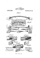
- FIG. 1 is a side elevation partly in section showing the present improvements applied in the manufacture of brake shoes, in connection with tubular inserts
- Fig. 2 is a top plan view of the same
- Fig. 3 is a front view of an alternative form of insert holding device especially applicable to inserts in the form of flat strips which are disposed in planes transverse to the brake shoe
- Fig. 4 is a sectional view of the same
- Fig. 5 is a front view of a further alternative form of insert holding device especially applicable to an insert in the form of a flat strip which is disposed in a plane longitudinal of the brake shoe
- Fig. 6 is a side view of the same
- Fig. 7 is a front view of a further alternative form of insert holding device especially applicable to inserts in the form of solid rods
- Fig. 8 is a sectional View of the same.
- Fig. 9 is a cross-section through a mold for casting the shoes.
- the ns holders comprise in all instances blocks 1. which are removably positioned in the mold at the ends of the openings formed by the patterns and which have means for detachable and positive supporting engagement with the ends of the inserts.
- Fig. 1 The form of construction shown in Fig. 1 is applicable to tubular inserts, shown at A. Three of these inserts are shown.
- the block 1 in this form has in end elevation the outline of a parallelogram in order to conform to the longitut'linal outline of the casting, (not shown) it being understood that the casting is a brake shoe.
- pins 3 Upon the inner face of the block 1 projecting pins 3 are provided.
- the pins 3 project axially from .coniform bosses 2 and while the provision of these bosses is preferred it is not necessary.
- the pins 3 project into the inserts, centering the latter and the inserts seat against the shoulders l which occur at the junction of said pins and said bosses. The latter project into the ends of the casting, forming corresponding coniform openings which lead to the inserts.
- Figs. 3 and 4 The construction shown on Figs. 3 and 4; is intended for inserts in the form of flat strips and which are arranged in planes transverse to the casting.
- the block is of the same general outline as that described in Fig. 1 and its inner face is provided with vertical grooves 5 corresponding to the number of inserts to be employed, and having at their lower ends lugs or steps 6 for positively supporting the inserts.
- the inserts are of a length to project beyond the casting at each end and that their projecting portions are centered in the grooves 5 resting on the said lug or steps 6 at the lower ends of said grooves.
- Figs. 5 and 6 The construction shown in Figs. 5 and 6 is intended for inserts in the form of flat strips which are arranged in planes longitudinal of the casting.
- the block 1 has the outline described and its inner face is provided with a transverse groove 7 it being assumed that only one insert is to be employed.
- the insert is of a length to project beyond the casting at each end, and its projecting end portions are centered and supported in the groove 7.
- Figs. 7 and 8 are especially applicable to inserts which are in the form of solid rods, although it may be used in connection with tubular inserts.
- the block 1, having the outline described is provided with openings 8 which extend from its inner face, correspond in number to the inserts, and receive the projecting ends of the latter thereby centering and supporting said inserts.
- the blocks may be readily and quickly stripped and the projecting portions of the inserts, if any there be, may be readily and quickly severed.
- a device for holding inserts to be permanently associated with a casting comprising a block shaped to fit at either end of the opening made by a pattern in a mold and having its inner face fashioned for detachable supporting engagement with the adjacent end of the insert, said block being adapted to cooperate in its supporting function with a similar block at the other end of said opening.
- a device for holding tubular inserts to be permanently associated with a brake shoe casting comprising a block having the general cross sectional outline of a parallelogram and having its inner face provided with one or more conical bosses and with stems projecting axially from said bosses.
Description
A. H. REID.
DEVICE FOR HOLDING INSERTS.
19211101111011 r1121) JUNE 14, 1011.
1,021,069. Patented Mar. 26, 1912.
ANDREW H. REID, OF TORONTO, ONTARIO, CANADA.
DEVICE FOR HOLDING INSERTS.
Application filed June 14, 1911.
Specification. of Letters Patent. Patented D131, 26, 1912.
Serial No. 633,124.
To all whom it may concern Be it known that I, ANDREW I-I'Uen' Item, a citizen of the Dominion of Canada, residing at Toronto, in the county of York, Province of Ontario, Canada, have invented certain new and useful Improvements in Devices for Holding Inserts, of which the following is a specification.
This invention relates to improvements in insert holding devices and it relates more particularly to devices for holding inserts which are permanently associated with castings such for instance as the reinforcing inserts for brake shoes.
Heretofore the inserted reinforcing pieces have been held by nails or equivalent devices, the shanks of which are driven into one of the members of the mold. This is objectionable however in that it requires considerable time and effort to position the insert and to finish the casting. The devices which form the subject of the present invention are used in pairs, one member of each pair being associated with a corresponding end of the insert; and said devices are so fashioned as to positively support the insert and at the same time to be readily and quickly disengaged therefrom.
Embodiments of the invention are disclosed in the accompanying drawings wherein Figure 1 is a side elevation partly in section showing the present improvements applied in the manufacture of brake shoes, in connection with tubular inserts; Fig. 2 is a top plan view of the same; Fig. 3 is a front view of an alternative form of insert holding device especially applicable to inserts in the form of flat strips which are disposed in planes transverse to the brake shoe; Fig. 4 is a sectional view of the same; Fig. 5 is a front view of a further alternative form of insert holding device especially applicable to an insert in the form of a flat strip which is disposed in a plane longitudinal of the brake shoe; Fig. 6 is a side view of the same; Fig. 7 is a front view of a further alternative form of insert holding device especially applicable to inserts in the form of solid rods; and Fig. 8 is a sectional View of the same. Fig. 9 is a cross-section through a mold for casting the shoes.
Similar characters of reference designate corresponding parts throughout the several views.
The ns holders comprise in all instances blocks 1. which are removably positioned in the mold at the ends of the openings formed by the patterns and which have means for detachable and positive supporting engagement with the ends of the inserts.
The form of construction shown in Fig. 1 is applicable to tubular inserts, shown at A. Three of these inserts are shown. The block 1 in this form has in end elevation the outline of a parallelogram in order to conform to the longitut'linal outline of the casting, (not shown) it being understood that the casting is a brake shoe. Upon the inner face of the block 1 projecting pins 3 are provided. In the embodiment shown the pins 3 project axially from .coniform bosses 2 and while the provision of these bosses is preferred it is not necessary. The pins 3 project into the inserts, centering the latter and the inserts seat against the shoulders l which occur at the junction of said pins and said bosses. The latter project into the ends of the casting, forming corresponding coniform openings which lead to the inserts.
The construction shown on Figs. 3 and 4; is intended for inserts in the form of flat strips and which are arranged in planes transverse to the casting. In this case the block is of the same general outline as that described in Fig. 1 and its inner face is provided with vertical grooves 5 corresponding to the number of inserts to be employed, and having at their lower ends lugs or steps 6 for positively supporting the inserts. It will be understood that the inserts are of a length to project beyond the casting at each end and that their projecting portions are centered in the grooves 5 resting on the said lug or steps 6 at the lower ends of said grooves.
The construction shown in Figs. 5 and 6 is intended for inserts in the form of flat strips which are arranged in planes longitudinal of the casting. The block 1 has the outline described and its inner face is provided with a transverse groove 7 it being assumed that only one insert is to be employed. In this case the insert is of a length to project beyond the casting at each end, and its projecting end portions are centered and supported in the groove 7.
The construction shown in Figs. 7 and 8 is especially applicable to inserts which are in the form of solid rods, although it may be used in connection with tubular inserts. In this case, the block 1, having the outline described is provided with openings 8 which extend from its inner face, correspond in number to the inserts, and receive the projecting ends of the latter thereby centering and supporting said inserts. Manifestly, after the article has been molded the blocks may be readily and quickly stripped and the projecting portions of the inserts, if any there be, may be readily and quickly severed.
Having fully described my invention, I claim 1. A device for holding inserts to be permanently associated with a casting and comprising a block shaped to fit at either end of the opening made by a pattern in a mold and having its inner face fashioned for detachable supporting engagement with the adjacent end of the insert, said block being adapted to cooperate in its supporting function with a similar block at the other end of said opening.
2. A device for holding inserts to be permanently associated with a casting and com prising a block shaped to fit at either end of the opening made by a pattern in a mold,
and having means for detachable supporting engagement with the adjacent end of the insert, said block being adapted to cooperate in its supporting function with a similar bloekat the other end of said openg A device for holding inserts to be permanently associated with a brake shoe casting and comprising a block having the general cross sectional outline of a parallelogram and having itsinner face fashioned for detachable supporting engagement with the adjacent end of the insert.
4. A device for holding tubular inserts to be permanently associated with a brake shoe casting and comprising a block having the general cross sectional outline of a parallelogram and having its inner face provided with one or more conical bosses and with stems projecting axially from said bosses.
In testimony whereof I affix my signature in presence of two witnesses.
ANDREW H. REID. lNitnesses ARTHUR F. LoBB, LILY HALL PAGE.
Copies of this patent may be obtained for five cents each, by addressing the Commissioner of Patents, Washington, D. G.
Priority Applications (1)
| Application Number | Priority Date | Filing Date | Title |
|---|---|---|---|
| US63312411A US1021069A (en) | 1911-06-14 | 1911-06-14 | Device for holding inserts. |
Applications Claiming Priority (1)
| Application Number | Priority Date | Filing Date | Title |
|---|---|---|---|
| US63312411A US1021069A (en) | 1911-06-14 | 1911-06-14 | Device for holding inserts. |
Publications (1)
| Publication Number | Publication Date |
|---|---|
| US1021069A true US1021069A (en) | 1912-03-26 |
Family
ID=3089366
Family Applications (1)
| Application Number | Title | Priority Date | Filing Date |
|---|---|---|---|
| US63312411A Expired - Lifetime US1021069A (en) | 1911-06-14 | 1911-06-14 | Device for holding inserts. |
Country Status (1)
| Country | Link |
|---|---|
| US (1) | US1021069A (en) |
-
1911
- 1911-06-14 US US63312411A patent/US1021069A/en not_active Expired - Lifetime
Similar Documents
| Publication | Publication Date | Title |
|---|---|---|
| US1021069A (en) | Device for holding inserts. | |
| US1838417A (en) | Art of casting | |
| US1080365A (en) | Saw. | |
| US1372209A (en) | Molding-flask for dentists' use | |
| US1838418A (en) | Art of casting | |
| US1236795A (en) | Clamp for molds. | |
| US970096A (en) | Art of forming castings. | |
| US1046468A (en) | Automatic self-cleaning spacer. | |
| US702620A (en) | Chaplet for supporting cores in molds. | |
| US531362A (en) | Apparatus for casting | |
| US656267A (en) | Artificial tooth. | |
| US356669A (en) | Mold for casting metallic articles | |
| US1036867A (en) | Well-tiling and mold therefor. | |
| US746161A (en) | Means for attaching turbine-buckets to wheels. | |
| US335839A (en) | pessano | |
| US407737A (en) | Frank fructuoso martin | |
| US1626003A (en) | Space band | |
| US775795A (en) | Mold for nuts or like articles. | |
| US309596A (en) | George r | |
| US745746A (en) | Method of manufacturing vises. | |
| US840999A (en) | Eye and pin for flasks. | |
| US535180A (en) | Coach pad | |
| US1186163A (en) | Buckle. | |
| US560537A (en) | Linotype-machine | |
| US134663A (en) | Improvement in attaching patterns to their supporting-plates |