US10208797B2 - Tapered roller bearing - Google Patents
Tapered roller bearing Download PDFInfo
- Publication number
- US10208797B2 US10208797B2 US14/884,261 US201514884261A US10208797B2 US 10208797 B2 US10208797 B2 US 10208797B2 US 201514884261 A US201514884261 A US 201514884261A US 10208797 B2 US10208797 B2 US 10208797B2
- Authority
- US
- United States
- Prior art keywords
- diameter
- inner ring
- section
- tapered
- collar portion
- Prior art date
- Legal status (The legal status is an assumption and is not a legal conclusion. Google has not performed a legal analysis and makes no representation as to the accuracy of the status listed.)
- Active, expires
Links
- 230000002829 reductive effect Effects 0.000 claims abstract description 45
- 230000000717 retained effect Effects 0.000 claims abstract description 8
- 238000005096 rolling process Methods 0.000 claims description 17
- 230000004323 axial length Effects 0.000 claims description 13
- 239000011347 resin Substances 0.000 claims description 6
- 229920005989 resin Polymers 0.000 claims description 6
- 230000007423 decrease Effects 0.000 claims description 3
- 238000000034 method Methods 0.000 description 4
- 238000010348 incorporation Methods 0.000 description 3
- 238000001746 injection moulding Methods 0.000 description 3
- XEEYBQQBJWHFJM-UHFFFAOYSA-N Iron Chemical compound [Fe] XEEYBQQBJWHFJM-UHFFFAOYSA-N 0.000 description 2
- 239000004519 grease Substances 0.000 description 2
- 238000012986 modification Methods 0.000 description 2
- 230000004048 modification Effects 0.000 description 2
- 230000001105 regulatory effect Effects 0.000 description 2
- 229910000831 Steel Inorganic materials 0.000 description 1
- 238000010276 construction Methods 0.000 description 1
- 238000010586 diagram Methods 0.000 description 1
- 230000002452 interceptive effect Effects 0.000 description 1
- 229910052742 iron Inorganic materials 0.000 description 1
- 230000000670 limiting effect Effects 0.000 description 1
- 230000036961 partial effect Effects 0.000 description 1
- 239000010959 steel Substances 0.000 description 1
Images


Classifications
-
- F—MECHANICAL ENGINEERING; LIGHTING; HEATING; WEAPONS; BLASTING
- F16—ENGINEERING ELEMENTS AND UNITS; GENERAL MEASURES FOR PRODUCING AND MAINTAINING EFFECTIVE FUNCTIONING OF MACHINES OR INSTALLATIONS; THERMAL INSULATION IN GENERAL
- F16C—SHAFTS; FLEXIBLE SHAFTS; ELEMENTS OR CRANKSHAFT MECHANISMS; ROTARY BODIES OTHER THAN GEARING ELEMENTS; BEARINGS
- F16C33/00—Parts of bearings; Special methods for making bearings or parts thereof
- F16C33/30—Parts of ball or roller bearings
- F16C33/58—Raceways; Race rings
- F16C33/583—Details of specific parts of races
- F16C33/585—Details of specific parts of races of raceways, e.g. ribs to guide the rollers
-
- F—MECHANICAL ENGINEERING; LIGHTING; HEATING; WEAPONS; BLASTING
- F16—ENGINEERING ELEMENTS AND UNITS; GENERAL MEASURES FOR PRODUCING AND MAINTAINING EFFECTIVE FUNCTIONING OF MACHINES OR INSTALLATIONS; THERMAL INSULATION IN GENERAL
- F16C—SHAFTS; FLEXIBLE SHAFTS; ELEMENTS OR CRANKSHAFT MECHANISMS; ROTARY BODIES OTHER THAN GEARING ELEMENTS; BEARINGS
- F16C19/00—Bearings with rolling contact, for exclusively rotary movement
- F16C19/22—Bearings with rolling contact, for exclusively rotary movement with bearing rollers essentially of the same size in one or more circular rows, e.g. needle bearings
- F16C19/34—Bearings with rolling contact, for exclusively rotary movement with bearing rollers essentially of the same size in one or more circular rows, e.g. needle bearings for both radial and axial load
- F16C19/36—Bearings with rolling contact, for exclusively rotary movement with bearing rollers essentially of the same size in one or more circular rows, e.g. needle bearings for both radial and axial load with a single row of rollers
- F16C19/364—Bearings with rolling contact, for exclusively rotary movement with bearing rollers essentially of the same size in one or more circular rows, e.g. needle bearings for both radial and axial load with a single row of rollers with tapered rollers, i.e. rollers having essentially the shape of a truncated cone
-
- F—MECHANICAL ENGINEERING; LIGHTING; HEATING; WEAPONS; BLASTING
- F16—ENGINEERING ELEMENTS AND UNITS; GENERAL MEASURES FOR PRODUCING AND MAINTAINING EFFECTIVE FUNCTIONING OF MACHINES OR INSTALLATIONS; THERMAL INSULATION IN GENERAL
- F16C—SHAFTS; FLEXIBLE SHAFTS; ELEMENTS OR CRANKSHAFT MECHANISMS; ROTARY BODIES OTHER THAN GEARING ELEMENTS; BEARINGS
- F16C33/00—Parts of bearings; Special methods for making bearings or parts thereof
- F16C33/30—Parts of ball or roller bearings
- F16C33/58—Raceways; Race rings
- F16C33/583—Details of specific parts of races
- F16C33/586—Details of specific parts of races outside the space between the races, e.g. end faces or bore of inner ring
-
- F—MECHANICAL ENGINEERING; LIGHTING; HEATING; WEAPONS; BLASTING
- F16—ENGINEERING ELEMENTS AND UNITS; GENERAL MEASURES FOR PRODUCING AND MAINTAINING EFFECTIVE FUNCTIONING OF MACHINES OR INSTALLATIONS; THERMAL INSULATION IN GENERAL
- F16C—SHAFTS; FLEXIBLE SHAFTS; ELEMENTS OR CRANKSHAFT MECHANISMS; ROTARY BODIES OTHER THAN GEARING ELEMENTS; BEARINGS
- F16C43/00—Assembling bearings
- F16C43/04—Assembling rolling-contact bearings
- F16C43/06—Placing rolling bodies in cages or bearings
-
- F—MECHANICAL ENGINEERING; LIGHTING; HEATING; WEAPONS; BLASTING
- F16—ENGINEERING ELEMENTS AND UNITS; GENERAL MEASURES FOR PRODUCING AND MAINTAINING EFFECTIVE FUNCTIONING OF MACHINES OR INSTALLATIONS; THERMAL INSULATION IN GENERAL
- F16C—SHAFTS; FLEXIBLE SHAFTS; ELEMENTS OR CRANKSHAFT MECHANISMS; ROTARY BODIES OTHER THAN GEARING ELEMENTS; BEARINGS
- F16C2240/00—Specified values or numerical ranges of parameters; Relations between them
- F16C2240/30—Angles, e.g. inclinations
- F16C2240/34—Contact angles
-
- F—MECHANICAL ENGINEERING; LIGHTING; HEATING; WEAPONS; BLASTING
- F16—ENGINEERING ELEMENTS AND UNITS; GENERAL MEASURES FOR PRODUCING AND MAINTAINING EFFECTIVE FUNCTIONING OF MACHINES OR INSTALLATIONS; THERMAL INSULATION IN GENERAL
- F16C—SHAFTS; FLEXIBLE SHAFTS; ELEMENTS OR CRANKSHAFT MECHANISMS; ROTARY BODIES OTHER THAN GEARING ELEMENTS; BEARINGS
- F16C2240/00—Specified values or numerical ranges of parameters; Relations between them
- F16C2240/40—Linear dimensions, e.g. length, radius, thickness, gap
- F16C2240/70—Diameters; Radii
Definitions
- the present invention relates to tapered roller bearings used as, for example, wheel bearings, and particularly to a technique for preventing inner ring raceways from being damaged during assembling.
- an outer diameter ⁇ d 2 of a small collar portion 7 of an inner ring 2 is set to be larger than an inscribed circle diameter ⁇ d 1 of a circle inscribed in arranged rollers such that the rollers or the retainer do not drop from the inner ring sub-assembly, for example, when the inner ring sub-assembly is incorporated into the outer ring or when other handling is performed.
- the inscribed circle diameter ⁇ d 1 is a diameter of a circle which is inscribed in arranged rollers 4 when an assembly 10 of the rollers and the retainer in which each roller 4 is retained by a retainer 5 has not been incorporated into the inner ring 2 .
- the outer diameter ⁇ d 2 of the small collar portion 7 is enlarged in an exaggerated manner as compared to the inscribed circle diameter ⁇ d 1 .
- difference between the diameters ⁇ d 1 and ⁇ d 2 cannot be visually recognized in practice.
- Patent Document 1 For ball bearings, suggestions for preventing dropping of balls and a retainer and preventing damage during incorporation in a case where an assembly of the balls and the retainer is incorporated into an inner ring, have been made (for example, Patent Document 1). However, for tapered roller bearings, similar suggestion has not been made.
- Patent Document 1 JP Laid-open Patent Publication No. 2010-127323
- the retainer when a resin retainer is used, the retainer is formed by injection molding so as to have a final shape obtained when the assembling into a bearing is completed. Therefore, when the assembly 10 of the rollers and the retainer is incorporated into the inner ring 2 , the retainer 5 is elastically deformed such that the inscribed circle diameter ⁇ d 1 for the arranged rollers is larger than the outer diameter ⁇ d 2 of the small collar portion 7 of the inner ring 2 . Thus, when each roller 4 passes over the small collar portion 7 of the inner ring 2 , the roller 4 is pressed against the small collar portion 7 . Thus, as shown in FIG.
- the roller 4 is tilted toward an inner ring raceway 2 a due to friction between the outer diameter surface of the small collar portion 7 and an edge, on the small diameter side, of the roller 4 , and an edge, on the large diameter side, of the roller 4 contacts with the inner ring raceway 2 a .
- the edge, on the large diameter side, of the roller 4 and the inner ring raceway 2 a rub against each other in a range indicated by L 1 in FIG. 8B , so that the inner ring raceway 2 a may be damaged.
- An object of the present invention is to provide a tapered roller bearing that allows an assembly of rollers and a retainer to be incorporated into an inner ring without damaging an inner ring raceway.
- a tapered roller bearing in accordance with the present invention includes: an inner ring; an outer ring; a plurality of tapered rollers interposed between the inner ring and the outer ring; a retainer that retains the tapered rollers so as to prevent the tapered rollers from being removed on an outer diameter side.
- the inner ring is formed with a small collar portion, and the small collar portion has a reduced diameter section at a location neighboring an inner ring raceway of the inner ring, the reduced diameter section having an outer diameter surface of a diameter smaller than the remaining section of the small collar portion, and an outer diameter ⁇ d 2 of the remaining section of the small collar portion is larger than an inscribed circle diameter ⁇ d 1 , and an outer diameter ⁇ d 3 of the reduced diameter section is smaller than the inscribed circle diameter ⁇ d 1 , where the inscribed circle diameter ⁇ d 1 represents a diameter of a circle that is inscribed in the arranged tapered rollers in an assembly of the rollers and the retainer, in a condition in which in the assembly, the tapered rollers are retained by the retainer and the assembly has not been incorporated into the inner ring.
- the reduced diameter section of the small collar portion may be continued to a base level diameter section on an end surface side of the small collar portion via a stepped section, and the outer diameter surface of the reduced diameter section may be formed as a cylindrical surface.
- the small collar portion may have a tapered section in which an outer diameter thereof gradually increases from an end on the inner ring raceway side toward an opposing side away from the inner ring raceway side, and a section of the tapered section having an outer diameter smaller than the inscribed circle diameter ⁇ d 1 may be defined as the reduced diameter section.
- the edge, on the large diameter side, of the tapered roller may not be strongly pressed against the inner ring raceway, whereby the inner ring raceway is not damaged.
- An axial length X from an end, on the base level diameter section side, of the reduced diameter section to an end, on a small diameter side, of the inner ring raceway may be defined so as to satisfy the following relational expression: X ⁇ RBAS ⁇ cos ⁇ ( ⁇ d 2/2)+ l sin ⁇ /tan ⁇
- a distance from a point of intersection of a bearing center axis and the inner ring raceway to an end surface, on the inner ring raceway side, of a large collar portion provided in the inner ring is represented as RBAS
- a tilt angle of the inner ring raceway relative to the bearing center axis is represented as ⁇
- a length of a rolling surface of the tapered roller is represented as l
- a tilt angle of the rolling surface of the tapered roller relative to an outer diameter surface, having a cylindrical shape, of the base level diameter section on the end surface side is represented as ⁇ .
- the edge, on the large diameter side, of the tapered roller can be prevented from being strongly pressed against the inner ring raceway.
- the rolling surface of the tapered roller in the assembly of the rollers and the retainer may be greased.
- FIG. 1 is a cross-sectional view of a tapered roller bearing according to a first embodiment of the present invention
- FIG. 2 is a cross-sectional view of an assembly of rollers and a retainer, and an inner ring in the tapered roller bearing;
- FIG. 3 is a cross-sectional view of a portion of the assembly of the rollers and the retainer
- FIG. 4A is a diagram showing dimensions of portions of the tapered roller bearing
- FIG. 4B is a partial view showing a different state of the tapered roller bearing
- FIG. 5A illustrates process steps of assembling the tapered roller bearing
- FIG. 5B illustrates process steps of assembling the tapered roller bearing
- FIG. 5C illustrates process steps of assembling the tapered roller bearing
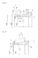
- FIG. 6 is a cross-sectional view of an inner ring of a tapered roller bearing according to a second embodiment of the present invention.
- FIG. 7 is a cross-sectional view of an inner ring of a tapered roller bearing according to a reference example
- FIG. 8A is a cross-sectional view illustrating a state immediately preceding incorporation of an assembly of rollers and a retainer into an inner ring of a conventional tapered roller bearing
- FIG. 8B is a cross-sectional view illustrating a state where the assembly of a conventional tapered roller bearing is being incorporated.
- FIG. 1 to FIG. 5A to 5C A first embodiment of the present invention will be described with reference to FIG. 1 to FIG. 5A to 5C .
- a tapered roller bearing 1 includes an inner ring 2 , an outer ring 3 , a plurality of tapered rollers 4 interposed between the inner ring 2 and the outer ring 3 , and a retainer 5 that retains the tapered rollers 4 .
- the inner ring 2 has on its outer circumference an inner ring raceway 2 a formed as a conical surface.
- the inner ring 2 has a large collar portion 6 and a small collar portion 7 on the large diameter side and the small diameter side, respectively, of the inner ring raceway 2 a .
- the inner ring raceway 2 a has recessed sections 2 b and 2 c formed at both ends, respectively.
- the outer ring 3 has on its inner circumference an outer ring raceway 3 a formed as a conical surface opposing the inner ring raceway 2 a , and the outer ring 3 has no collar portion.
- Each of the tapered rollers 4 has on its outer circumference a rolling surface 4 a , and is capable of rolling between the inner ring raceway 2 a and the outer ring raceway 3 a .
- the retainer 5 has a plurality of pockets 5 a ( FIG. 3 ) spaced from each other at predetermined intervals in the circumferential direction, and retains the tapered rollers 4 in the pockets 5 a , respectively.
- the retainer 5 is made of, for example, resin, and produced by injection molding.
- the small collar portion 7 of the inner ring 2 has a base level diameter section 7 a on an end surface 2 d side, and a reduced diameter section 7 b neighboring the inner ring raceway 2 a and having an outer diameter surface having a diameter smaller than that of the base level diameter section 7 a .
- the base level diameter section 7 a and the reduced diameter section 7 b have respective outer diameter surfaces each in the form of a cylindrical surface.
- An outer diameter ⁇ d 2 of the base level diameter section 7 a is larger than an inscribed circle diameter ⁇ d 1 of a circle inscribed in the arranged tapered rollers 4
- an outer diameter ⁇ d 3 of the reduced diameter section is smaller than the inscribed circle diameter ⁇ d 1 .
- the inscribed circle diameter ⁇ d 1 represents a diameter obtained in a condition in which in an assembly 10 of the rollers and the retainer the tapered rollers 4 are retained by the retainer 5 and the assembly has not been incorporated into the inner ring 2 .
- each pocket 5 a of the retainer 5 is shaped so as to be narrowed on the outer diameter side and widened on the inner diameter side.
- the tapered rollers 4 are inserted into the pockets 5 a from the inner diameter side to form the assembly 10 of the rollers and the retainer.
- the tapered rollers 4 can be inserted into or removed from the pockets 5 a on the inner diameter side, and are prevented from being removed on the outer diameter side.
- the assembly 10 of the rollers and the retainer is placed on the horizontal surface or the like such that the small diameter side of the retainer 5 is the lower side when the assembly 10 is incorporated into the inner ring 2 as shown in FIG. 5A . In this condition, the tapered rollers 4 in the respective pockets 5 a are tilted toward the outer diameter side to contact with the retainer 5 .
- the condition in which the assembly 10 has not been incorporated, described above represents this state.
- the base level diameter section 7 a is continued to the reduced diameter section 7 b via a stepped section 7 c . Therefore, the reduced diameter section 7 b has a diameter smaller than the remaining section (the base level diameter section 7 a and the stepped section 7 c ) of the small collar portion 7 .
- the stepped section 7 c is formed as a tilt surface that has its diameter gradually decreases from the base level diameter section 7 a side toward the reduced diameter section 7 b .
- a tilt angle ⁇ 2 of the stepped section 7 c may be, but is not limited to, about 45°.
- chamfered portions R having an arc-shaped cross-section are formed, respectively. Further, in the end portion on the inner ring raceway 2 a side of the reduced diameter section 7 b , a chamfered portion R having an arc-shaped cross-section is formed.
- a position A, at an end on the base level diameter section side, of the reduced diameter section 7 b (in this example, the end on the stepped section 7 c side) is defined as follows (see FIG. 4A ). Specifically, where a distance from a point of intersection O of a bearing center axis C and the inner ring raceway 2 a to an end surface 6 a , on the inner ring raceway 2 a side, of the large collar portion 6 is represented as RBAS, a tilt angle of the inner ring raceway 2 a relative to the bearing center axis C is represented as ⁇ , a length of the rolling surface 4 a of the tapered roller 4 is represented as 1, and a tilt angle of the rolling surface 4 a of the tapered roller 4 relative to an outer diameter surface of the base level diameter section 7 a of the small collar portion 7 is represented as ⁇ , the position A is defined such that an axial length X from the position A to a position B at the end, on the small diameter side, of the inner ring raceway 2
- the tapered roller bearing 1 is assembled.
- the tapered rollers 4 are retained in the respective pockets of the retainer 5 disposed such that the small diameter side of the retainer is the lower side, to form the assembly 10 of the rollers and the retainer.
- the rolling surfaces 4 a of the respective tapered rollers 4 in the assembly 10 of the rollers and the retainer or the inner ring raceway 2 a are greased.
- the inner ring raceway 2 a is less likely to be damaged due to contact with the tapered rollers 4 .
- FIGS. 5A to 5C only a portion of the plural tapered rollers 4 in the assembly 10 of the rollers and the retainer is shown.
- the inner ring 2 is incorporated with the inner circumferential side portions of the tapered rollers 4 in the assembly 10 of the rollers and the retainer, to form an inner ring sub-assembly 11 as shown in FIG. 5C .
- movement of each tapered roller 4 in the axial direction is regulated by the large collar portion 6 and the small collar portion 7 of the inner ring 2
- movement of each tapered roller 4 toward the outer diameter side is regulated by the retainer 5 . Therefore, the tapered rollers 4 and the retainer 5 are prevented from dropping from the inner ring 2 .
- the inner ring sub-assembly 11 is incorporated into the outer ring 3 . Since the tapered rollers 4 and the retainer 5 do not drop from the inner ring 2 , incorporation of the inner ring sub-assembly 11 and other handling operations can be facilitated.
- the retainer 5 made of resin is produced by, for example, injection molding, so as to have a final shape obtained when assembling into the bearing is completed. Therefore, when the retainer assembly 10 is incorporated into the inner ring 2 , the retainer 5 is elastically deformed such that the inscribed circle diameter ⁇ 1 for the arranged rollers is larger than the outer diameter ⁇ d 2 of the base level diameter section 7 a of the small collar portion 7 of the inner ring 2 . If the small collar portion 7 does not have the reduced diameter section 7 b as indicated by a broken line in FIG.
- the tapered roller 4 when the end, on the small diameter side, of each tapered roller 4 is disposed in a range of the axial length X, the tapered roller 4 is not pressed by the small collar portion 7 . Therefore, as shown in FIG. 4B , the tapered rollers 4 are maintained at normal positions at which no external force acts on the tapered rollers 4 . Therefore, the edge, on the large diameter side, of the tapered roller 4 and the inner ring raceway 2 a do not rub against each other, and the inner ring raceway 2 a can be prevented from being damaged.
- the chamfered portion R having an arc-shaped cross-section is formed at each corner portion of the outer diameter surface of the small collar portion 7 , damage due to contact between the small collar portion 7 and the tapered rollers 4 can be also prevented.
- the axial length X is derived as follows.
- an axial distance L 1 from the edge, on the large diameter side, of the tapered roller 4 to the end surface 6 a , on the inner ring raceway 2 a side, of the large collar portion 6 is set so as to have the same value as the axial length X when the edge, on the small diameter side, of the tapered roller 4 is positioned at the same axial portion as the position A.
- the value of the axial length X can be minimized.
- An axial distance L 2 from the point of intersection O to the end surface 6 a , on the inner ring raceway 2 a side, of the large collar portion 6 is represented as follows.
- L 2 RBAS ⁇ cos ⁇ (Expression 2)
- An axial distance L 3 from the point of intersection O to the edge, on the large diameter side, of the tapered roller 4 is represented as follows.
- L 3 ⁇ ( ⁇ d 2/2)+ l sin ⁇ /tan ⁇ (Expression 3)
- the axial length X is represented as follows.
- FIG. 6 shows a second embodiment of the present invention.
- the small collar portion 7 of the inner ring 2 has the base level diameter section 7 a on the end surface side, and a tapered section 7 d on the inner ring raceway 2 a side.
- the base level diameter section 7 a has an outer diameter surface in the form of a cylindrical surface.
- the tapered section 7 d has such a tapered shape that its outer diameter is enlarged from the end on the inner ring raceway 2 a side toward an opposing side away from the inner ring raceway 2 a side.
- a section, of the tapered section 7 d having an outer diameter smaller than the inscribed circle diameter ⁇ d 1 is defined as a reduced diameter section 7 da .
- the reduced diameter section 7 da has a diameter smaller than the remaining sections (the base level diameter section 7 a and a portion of the tapered section 7 d ) of the small collar portion 7 .
- the other components are the same as in the embodiment described with reference to FIG. 1 to FIGS. 4A, 4B , and illustration and description thereof are not given.
- the position A is defined such that the axial length X from the position A (in this example, a position at which the reduced diameter section 7 da has a maximum outer diameter) at the end, on the base level diameter section side, of the reduced diameter section 7 da , to the position B at the end, on the small diameter side, of the inner ring raceway 2 a is represented by Expression 1 described above.
- the small collar portion 7 of the inner ring 2 may be a component separate from an inner ring body 2 A as shown in FIG. 7 , and after the assembly 10 of the rollers and the retainer has been incorporated into the inner ring 2 , the small collar portion 7 may be attached to the inner ring body 2 A.
- the small collar portion 7 is obtained by a link-like steel plate being formed so as to have an L-shaped cross-section.
- the small collar portion 7 is fitted, with an interference, to an outer diameter surface of a small collar portion mounting section 2 d of the inner ring body 2 A, whereby the small collar portion 7 is mounted to the inner ring body 2 A.
- a diameter ⁇ d 4 of the outer diameter surface of the small collar portion mounting section 2 d is smaller than a diameter ⁇ d 5 of an end, on the small diameter side, of the inner ring raceway 2 a .
- the small collar portion 7 is mounted to the small collar portion mounting section 2 d at a position at which interfering with the retainer 5 does not occur when the bearing rotates.
Landscapes
- Engineering & Computer Science (AREA)
- General Engineering & Computer Science (AREA)
- Mechanical Engineering (AREA)
- Rolling Contact Bearings (AREA)
- Mounting Of Bearings Or Others (AREA)
Abstract
Description
X≥RBAS·cos θ−{(ϕd2/2)+l sin α}/tan θ
X≥RBAS·cos θ−{(ϕd2/2)+l sin α}/tan θ (Expression 1)
where 0≤α≤θ is satisfied. The reason for the above definition will be described later.
L2=RBAS·cos θ (Expression 2)
An axial distance L3 from the point of intersection O to the edge, on the large diameter side, of the tapered
L3={(ϕd2/2)+l sin α}/tan θ (Expression 3)
According to
X=RBAS·cos θ−{(ϕd2/2)+l sin α}/tan θ (Expression 4)
Therefore, by the axial length X being defined as in
-
- 1 . . . Tapered roller bearing
- 2 . . . Inner ring
- 2A . . . Inner ring body
- 2 a . . . Inner ring raceway
- 2 b . . . Recessed section on large collar portion side
- 2 c . . . Recessed section on small collar portion side
- 2 d . . . Small collar portion mounting section
- 3 . . . Outer ring
- 3 a . . . Outer ring raceway
- 4 . . . Tapered roller
- 4 a . . . Rolling surface
- 5 . . . Retainer
- 5 a . . . Pocket
- 6 . . . Large collar portion
- 6 a . . . End surface, on inner ring raceway side, of large collar portion
- 7 . . . Small collar portion
- 7 a . . . Base level diameter section
- 7 b . . . Reduced diameter section
- 7 c . . . Stepped section
- 7 d . . . Tapered section
- 7 da . . . Reduced diameter section
- 10 . . . Assembly of rollers and retainer
- 11 . . . Inner ring sub-assembly
- C . . . Bearing center axis
- O . . . Point of intersection
- ϕd1 . . . Inscribed circle diameter
- ϕd2 . . . Outer diameter of small collar portion
- ϕd3 . . . Outer diameter of reduced diameter section
- ϕd4 . . . Outer diameter of small collar portion mounting section
- ϕd5 . . . Outer diameter of end, on small diameter side, of inner ring raceway
- θ . . . Tilt angle of inner ring raceway
- θ2 . . . Tilt angle of rolling surface of tapered roller relative to outer diameter surface of reduced diameter section
- α . . . Tilt angle of rolling surface of tapered roller relative to outer diameter surface of base level diameter section
- RBAS . . . Distance from point of intersection of bearing center axis and inner ring raceway to end surface of large collar portion of inner ring
- X . . . Axial length
- L1, L2, L3 . . . Axial distance
- l . . . Length of rolling surface of tapered roller
Claims (4)
X≥RBAS·cos θ−{(ϕd2/2)+L·sin α}/tan θ
Applications Claiming Priority (3)
| Application Number | Priority Date | Filing Date | Title |
|---|---|---|---|
| JP2013086457A JP6153761B2 (en) | 2013-04-17 | 2013-04-17 | Tapered roller bearing |
| JP2013-086457 | 2013-04-17 | ||
| PCT/JP2014/060480 WO2014171405A1 (en) | 2013-04-17 | 2014-04-11 | Tapered roller bearing |
Related Parent Applications (1)
| Application Number | Title | Priority Date | Filing Date |
|---|---|---|---|
| PCT/JP2014/060480 Continuation WO2014171405A1 (en) | 2013-04-17 | 2014-04-11 | Tapered roller bearing |
Publications (2)
| Publication Number | Publication Date |
|---|---|
| US20160032974A1 US20160032974A1 (en) | 2016-02-04 |
| US10208797B2 true US10208797B2 (en) | 2019-02-19 |
Family
ID=51731347
Family Applications (1)
| Application Number | Title | Priority Date | Filing Date |
|---|---|---|---|
| US14/884,261 Active 2034-11-16 US10208797B2 (en) | 2013-04-17 | 2015-10-15 | Tapered roller bearing |
Country Status (5)
| Country | Link |
|---|---|
| US (1) | US10208797B2 (en) |
| EP (1) | EP2988008B1 (en) |
| JP (1) | JP6153761B2 (en) |
| CN (1) | CN105143693B (en) |
| WO (1) | WO2014171405A1 (en) |
Families Citing this family (3)
| Publication number | Priority date | Publication date | Assignee | Title |
|---|---|---|---|---|
| JP6778310B2 (en) * | 2018-12-07 | 2020-10-28 | Ntn株式会社 | Tapered roller bearing |
| DE102021108401A1 (en) | 2021-04-01 | 2022-10-06 | Schaeffler Technologies AG & Co. KG | tapered roller bearing |
| CN116538200A (en) * | 2023-06-14 | 2023-08-04 | 济南齐贝斯轴承科技有限公司 | Middle-large-sized assembly chamfer tapered roller bearing |
Citations (20)
| Publication number | Priority date | Publication date | Assignee | Title |
|---|---|---|---|---|
| JPS5520988A (en) | 1978-07-24 | 1980-02-14 | Timken Co | Roller bearing construction |
| DE3520814A1 (en) | 1985-06-11 | 1986-12-11 | INA Wälzlager Schaeffler KG, 8522 Herzogenaurach | Cage for angular-contact roller bearings |
| US4728204A (en) | 1985-11-22 | 1988-03-01 | Riv-Skf Officine Di Villar Perosa S.P.A. | Taper roller bearing, particularly for railway use |
| JP2001208054A (en) | 2000-01-24 | 2001-08-03 | Nsk Ltd | Tapered roller bearing |
| JP2002061655A (en) | 2000-08-16 | 2002-02-28 | Ntn Corp | Tapered roller bearing |
| US20020044707A1 (en) | 2000-10-17 | 2002-04-18 | Kimihiro Hanai | Tapered roller bearing |
| EP1510707A2 (en) | 2003-08-28 | 2005-03-02 | Ntn Corporation | Tapered roller bearing for automobile transmission |
| US20050047700A1 (en) | 2003-08-28 | 2005-03-03 | Takashi Tsujimoto | Tapered roller bearing for automobile transmission |
| WO2005045269A1 (en) | 2003-11-07 | 2005-05-19 | Jtekt Corporation | Oil lubrication-type rolling bearing device |
| US20070047865A1 (en) | 2005-08-25 | 2007-03-01 | Eiichi Nakamizo | Tapered roller bearing |
| JP2007321939A (en) | 2006-06-05 | 2007-12-13 | Nsk Ltd | Bearing assembly method, rolling bearing and bearing cage |
| JP2007321940A (en) | 2006-06-05 | 2007-12-13 | Nsk Ltd | Bearing cage, rolling bearing, and bearing assembly method |
| JP2008008466A (en) | 2006-06-30 | 2008-01-17 | Nsk Ltd | Tapered roller bearing |
| JP2008180375A (en) | 2006-12-28 | 2008-08-07 | Ntn Corp | Conical rolling bearing |
| JP2008261368A (en) | 2007-04-10 | 2008-10-30 | Ntn Corp | Tapered roller bearing |
| JP2010127323A (en) | 2008-11-26 | 2010-06-10 | Ntn Corp | Wheel bearing |
| JP2011208725A (en) | 2010-03-30 | 2011-10-20 | Jtekt Corp | Tapered roller bearing |
| JP2012013134A (en) | 2010-06-30 | 2012-01-19 | Ntn Corp | Conical roller bearing |
| JP2012036993A (en) | 2010-08-09 | 2012-02-23 | Nsk Ltd | Tapered roller bearing |
| JP2013040634A (en) | 2011-08-11 | 2013-02-28 | Nsk Ltd | Assembling method of conical rolling bearing and conical rolling bearing |
-
2013
- 2013-04-17 JP JP2013086457A patent/JP6153761B2/en active Active
-
2014
- 2014-04-11 EP EP14785432.7A patent/EP2988008B1/en active Active
- 2014-04-11 WO PCT/JP2014/060480 patent/WO2014171405A1/en not_active Ceased
- 2014-04-11 CN CN201480021114.2A patent/CN105143693B/en active Active
-
2015
- 2015-10-15 US US14/884,261 patent/US10208797B2/en active Active
Patent Citations (28)
| Publication number | Priority date | Publication date | Assignee | Title |
|---|---|---|---|---|
| JPS5520988A (en) | 1978-07-24 | 1980-02-14 | Timken Co | Roller bearing construction |
| US4203635A (en) | 1978-07-24 | 1980-05-20 | The Timken Company | Wheel mounting and tapered roller bearing therefor |
| DE3520814A1 (en) | 1985-06-11 | 1986-12-11 | INA Wälzlager Schaeffler KG, 8522 Herzogenaurach | Cage for angular-contact roller bearings |
| US4728204A (en) | 1985-11-22 | 1988-03-01 | Riv-Skf Officine Di Villar Perosa S.P.A. | Taper roller bearing, particularly for railway use |
| JP2001208054A (en) | 2000-01-24 | 2001-08-03 | Nsk Ltd | Tapered roller bearing |
| JP2002061655A (en) | 2000-08-16 | 2002-02-28 | Ntn Corp | Tapered roller bearing |
| US20020044707A1 (en) | 2000-10-17 | 2002-04-18 | Kimihiro Hanai | Tapered roller bearing |
| EP1510707A2 (en) | 2003-08-28 | 2005-03-02 | Ntn Corporation | Tapered roller bearing for automobile transmission |
| US20050047700A1 (en) | 2003-08-28 | 2005-03-03 | Takashi Tsujimoto | Tapered roller bearing for automobile transmission |
| US20050047699A1 (en) | 2003-08-28 | 2005-03-03 | Takashi Tsujimoto | Tapered roller bearing for automobile transmission |
| US20080013875A1 (en) | 2003-08-28 | 2008-01-17 | Ntn Corporation | Operation method of tapered roller bearing for automobile transmission |
| WO2005045269A1 (en) | 2003-11-07 | 2005-05-19 | Jtekt Corporation | Oil lubrication-type rolling bearing device |
| US20070133914A1 (en) | 2003-11-07 | 2007-06-14 | Hiroki Matsuyama | Oil lubricated rolling bearing device |
| US20070047865A1 (en) | 2005-08-25 | 2007-03-01 | Eiichi Nakamizo | Tapered roller bearing |
| JP2007321940A (en) | 2006-06-05 | 2007-12-13 | Nsk Ltd | Bearing cage, rolling bearing, and bearing assembly method |
| JP2007321939A (en) | 2006-06-05 | 2007-12-13 | Nsk Ltd | Bearing assembly method, rolling bearing and bearing cage |
| JP2008008466A (en) | 2006-06-30 | 2008-01-17 | Nsk Ltd | Tapered roller bearing |
| JP2008180375A (en) | 2006-12-28 | 2008-08-07 | Ntn Corp | Conical rolling bearing |
| US20100316321A1 (en) | 2006-12-28 | 2010-12-16 | Eiichi Nakamizo | Tapered roller bearing |
| JP2008261368A (en) | 2007-04-10 | 2008-10-30 | Ntn Corp | Tapered roller bearing |
| JP2010127323A (en) | 2008-11-26 | 2010-06-10 | Ntn Corp | Wheel bearing |
| JP2011208725A (en) | 2010-03-30 | 2011-10-20 | Jtekt Corp | Tapered roller bearing |
| JP2012013134A (en) | 2010-06-30 | 2012-01-19 | Ntn Corp | Conical roller bearing |
| CN102918287A (en) | 2010-06-30 | 2013-02-06 | Ntn株式会社 | Tapered roller bearing |
| US20130089285A1 (en) | 2010-06-30 | 2013-04-11 | Yasuhiro Shimizu | Tapered roller bearing |
| US8899840B2 (en) | 2010-06-30 | 2014-12-02 | Ntn Corporation | Tapered roller bearing |
| JP2012036993A (en) | 2010-08-09 | 2012-02-23 | Nsk Ltd | Tapered roller bearing |
| JP2013040634A (en) | 2011-08-11 | 2013-02-28 | Nsk Ltd | Assembling method of conical rolling bearing and conical rolling bearing |
Non-Patent Citations (7)
| Title |
|---|
| Chinese Office Action dated Dec. 2, 2016 in corresponding Chinese Patent Application No. 20148002114.2. |
| Chinese Office Action dated Jun. 9, 2017 in corresponding Chinese Patent Application No. 201480021114.2. |
| Extended European Search Report dated Jan. 12, 2017 in corresponding European Patent Application No. 14785432.7. |
| International Search Report dated Jul. 15, 2014 in corresponding international application PCT/JP2014/060480. |
| Japanese Office Action dated Dec. 6, 2016 in corresponding Japanese Patent Application No. 2013-086457. |
| Machine Translation of JP 2001-208054 dated Jan. 2008. * |
| PCT International Preliminary Report on Patentability dated Oct. 29, 2015 in corresponding International Patent Application No. PCT/JP2014/060480. |
Also Published As
| Publication number | Publication date |
|---|---|
| JP6153761B2 (en) | 2017-06-28 |
| EP2988008A4 (en) | 2017-02-08 |
| WO2014171405A1 (en) | 2014-10-23 |
| CN105143693B (en) | 2017-11-28 |
| EP2988008B1 (en) | 2018-08-08 |
| JP2014211175A (en) | 2014-11-13 |
| EP2988008A1 (en) | 2016-02-24 |
| CN105143693A (en) | 2015-12-09 |
| US20160032974A1 (en) | 2016-02-04 |
Similar Documents
| Publication | Publication Date | Title |
|---|---|---|
| US7427163B2 (en) | Self-aligning antifriction bearing and cage for said self-aligning antifriction bearing | |
| US8480305B2 (en) | Resin cage for angular contact ball bearing | |
| US6783279B2 (en) | Angular contact ball-bearing cage with lubricant pockets | |
| US10151346B2 (en) | Ball bearing | |
| US20110229067A1 (en) | Bearing cages with high speed features | |
| US10054164B2 (en) | Rolling bearing | |
| US10208797B2 (en) | Tapered roller bearing | |
| EP2988010B1 (en) | Angular ball bearing cage | |
| US20090080825A1 (en) | Angular contact ball bearing | |
| US8591121B2 (en) | Rolling bearing cage and assembly | |
| US10527096B2 (en) | Rolling bearing | |
| US10514063B2 (en) | Rolling bearing | |
| JP6019703B2 (en) | Self-aligning roller bearing with sealing device and manufacturing method thereof | |
| JP2008291921A (en) | Resin cage for tapered roller bearing and tapered roller bearing | |
| US8834033B2 (en) | Ball bearing having segmented and integral races | |
| EP2706249B1 (en) | Resin cage and roller bearing | |
| EP2990672A1 (en) | Rolling bearing | |
| US8864386B2 (en) | Roller bearing and cage for a roller bearing | |
| CN110131306B (en) | Rolling bearing and static ring thereof | |
| JP6554831B2 (en) | Tapered roller bearing | |
| US8920039B2 (en) | Tandem rolling bearings with open cage | |
| US20170241476A1 (en) | Bearing having an outer ring and rolling element piloted cage | |
| JP2016023707A (en) | Self-aligning roller bearing | |
| WO2018173731A1 (en) | Sealed rolling bearing | |
| CN119594114A (en) | Bearing device for wheel |
Legal Events
| Date | Code | Title | Description |
|---|---|---|---|
| AS | Assignment |
Owner name: NTN CORPORATION, JAPAN Free format text: ASSIGNMENT OF ASSIGNORS INTEREST;ASSIGNOR:NOMURA, SHOHEI;REEL/FRAME:036811/0459 Effective date: 20150911 |
|
| AS | Assignment |
Owner name: NTN CORPORATION, JAPAN Free format text: CORRECTIVE ASSIGNMENT TO CORRECT THE ASSIGNOR'S NAME PREVIOUSLY RECORDED ON REEL 036811 FRAME 0459. ASSIGNOR(S) HEREBY CONFIRMS THE SHUHEI NOMURA;ASSIGNOR:NOMURA, SHUHEI;REEL/FRAME:038808/0688 Effective date: 20150911 |
|
| STCF | Information on status: patent grant |
Free format text: PATENTED CASE |
|
| CC | Certificate of correction | ||
| MAFP | Maintenance fee payment |
Free format text: PAYMENT OF MAINTENANCE FEE, 4TH YEAR, LARGE ENTITY (ORIGINAL EVENT CODE: M1551); ENTITY STATUS OF PATENT OWNER: LARGE ENTITY Year of fee payment: 4 |