US10197817B2 - Substrate and manufacturing method thereof, and display device - Google Patents
Substrate and manufacturing method thereof, and display device Download PDFInfo
- Publication number
- US10197817B2 US10197817B2 US15/507,122 US201615507122A US10197817B2 US 10197817 B2 US10197817 B2 US 10197817B2 US 201615507122 A US201615507122 A US 201615507122A US 10197817 B2 US10197817 B2 US 10197817B2
- Authority
- US
- United States
- Prior art keywords
- substrate
- black matrix
- reflection pattern
- tin oxide
- indium tin
- Prior art date
- Legal status (The legal status is an assumption and is not a legal conclusion. Google has not performed a legal analysis and makes no representation as to the accuracy of the status listed.)
- Active
Links
Images


Classifications
-
- G—PHYSICS
- G02—OPTICS
- G02F—OPTICAL DEVICES OR ARRANGEMENTS FOR THE CONTROL OF LIGHT BY MODIFICATION OF THE OPTICAL PROPERTIES OF THE MEDIA OF THE ELEMENTS INVOLVED THEREIN; NON-LINEAR OPTICS; FREQUENCY-CHANGING OF LIGHT; OPTICAL LOGIC ELEMENTS; OPTICAL ANALOGUE/DIGITAL CONVERTERS
- G02F1/00—Devices or arrangements for the control of the intensity, colour, phase, polarisation or direction of light arriving from an independent light source, e.g. switching, gating or modulating; Non-linear optics
- G02F1/01—Devices or arrangements for the control of the intensity, colour, phase, polarisation or direction of light arriving from an independent light source, e.g. switching, gating or modulating; Non-linear optics for the control of the intensity, phase, polarisation or colour
- G02F1/13—Devices or arrangements for the control of the intensity, colour, phase, polarisation or direction of light arriving from an independent light source, e.g. switching, gating or modulating; Non-linear optics for the control of the intensity, phase, polarisation or colour based on liquid crystals, e.g. single liquid crystal display cells
- G02F1/133—Constructional arrangements; Operation of liquid crystal cells; Circuit arrangements
- G02F1/1333—Constructional arrangements; Manufacturing methods
- G02F1/1335—Structural association of cells with optical devices, e.g. polarisers or reflectors
- G02F1/133509—Filters, e.g. light shielding masks
- G02F1/133512—Light shielding layers, e.g. black matrix
-
- G—PHYSICS
- G02—OPTICS
- G02F—OPTICAL DEVICES OR ARRANGEMENTS FOR THE CONTROL OF LIGHT BY MODIFICATION OF THE OPTICAL PROPERTIES OF THE MEDIA OF THE ELEMENTS INVOLVED THEREIN; NON-LINEAR OPTICS; FREQUENCY-CHANGING OF LIGHT; OPTICAL LOGIC ELEMENTS; OPTICAL ANALOGUE/DIGITAL CONVERTERS
- G02F1/00—Devices or arrangements for the control of the intensity, colour, phase, polarisation or direction of light arriving from an independent light source, e.g. switching, gating or modulating; Non-linear optics
- G02F1/01—Devices or arrangements for the control of the intensity, colour, phase, polarisation or direction of light arriving from an independent light source, e.g. switching, gating or modulating; Non-linear optics for the control of the intensity, phase, polarisation or colour
- G02F1/0102—Constructional details, not otherwise provided for in this subclass
-
- G—PHYSICS
- G02—OPTICS
- G02F—OPTICAL DEVICES OR ARRANGEMENTS FOR THE CONTROL OF LIGHT BY MODIFICATION OF THE OPTICAL PROPERTIES OF THE MEDIA OF THE ELEMENTS INVOLVED THEREIN; NON-LINEAR OPTICS; FREQUENCY-CHANGING OF LIGHT; OPTICAL LOGIC ELEMENTS; OPTICAL ANALOGUE/DIGITAL CONVERTERS
- G02F1/00—Devices or arrangements for the control of the intensity, colour, phase, polarisation or direction of light arriving from an independent light source, e.g. switching, gating or modulating; Non-linear optics
- G02F1/01—Devices or arrangements for the control of the intensity, colour, phase, polarisation or direction of light arriving from an independent light source, e.g. switching, gating or modulating; Non-linear optics for the control of the intensity, phase, polarisation or colour
- G02F1/13—Devices or arrangements for the control of the intensity, colour, phase, polarisation or direction of light arriving from an independent light source, e.g. switching, gating or modulating; Non-linear optics for the control of the intensity, phase, polarisation or colour based on liquid crystals, e.g. single liquid crystal display cells
- G02F1/133—Constructional arrangements; Operation of liquid crystal cells; Circuit arrangements
- G02F1/1333—Constructional arrangements; Manufacturing methods
- G02F1/1335—Structural association of cells with optical devices, e.g. polarisers or reflectors
- G02F1/133502—Antiglare, refractive index matching layers
-
- G—PHYSICS
- G02—OPTICS
- G02F—OPTICAL DEVICES OR ARRANGEMENTS FOR THE CONTROL OF LIGHT BY MODIFICATION OF THE OPTICAL PROPERTIES OF THE MEDIA OF THE ELEMENTS INVOLVED THEREIN; NON-LINEAR OPTICS; FREQUENCY-CHANGING OF LIGHT; OPTICAL LOGIC ELEMENTS; OPTICAL ANALOGUE/DIGITAL CONVERTERS
- G02F1/00—Devices or arrangements for the control of the intensity, colour, phase, polarisation or direction of light arriving from an independent light source, e.g. switching, gating or modulating; Non-linear optics
- G02F1/01—Devices or arrangements for the control of the intensity, colour, phase, polarisation or direction of light arriving from an independent light source, e.g. switching, gating or modulating; Non-linear optics for the control of the intensity, phase, polarisation or colour
- G02F1/13—Devices or arrangements for the control of the intensity, colour, phase, polarisation or direction of light arriving from an independent light source, e.g. switching, gating or modulating; Non-linear optics for the control of the intensity, phase, polarisation or colour based on liquid crystals, e.g. single liquid crystal display cells
- G02F1/133—Constructional arrangements; Operation of liquid crystal cells; Circuit arrangements
- G02F1/1333—Constructional arrangements; Manufacturing methods
- G02F1/1335—Structural association of cells with optical devices, e.g. polarisers or reflectors
- G02F1/133553—Reflecting elements
-
- G—PHYSICS
- G02—OPTICS
- G02F—OPTICAL DEVICES OR ARRANGEMENTS FOR THE CONTROL OF LIGHT BY MODIFICATION OF THE OPTICAL PROPERTIES OF THE MEDIA OF THE ELEMENTS INVOLVED THEREIN; NON-LINEAR OPTICS; FREQUENCY-CHANGING OF LIGHT; OPTICAL LOGIC ELEMENTS; OPTICAL ANALOGUE/DIGITAL CONVERTERS
- G02F1/00—Devices or arrangements for the control of the intensity, colour, phase, polarisation or direction of light arriving from an independent light source, e.g. switching, gating or modulating; Non-linear optics
- G02F1/01—Devices or arrangements for the control of the intensity, colour, phase, polarisation or direction of light arriving from an independent light source, e.g. switching, gating or modulating; Non-linear optics for the control of the intensity, phase, polarisation or colour
- G02F1/13—Devices or arrangements for the control of the intensity, colour, phase, polarisation or direction of light arriving from an independent light source, e.g. switching, gating or modulating; Non-linear optics for the control of the intensity, phase, polarisation or colour based on liquid crystals, e.g. single liquid crystal display cells
- G02F1/133—Constructional arrangements; Operation of liquid crystal cells; Circuit arrangements
- G02F1/136—Liquid crystal cells structurally associated with a semi-conducting layer or substrate, e.g. cells forming part of an integrated circuit
- G02F1/1362—Active matrix addressed cells
- G02F1/136209—Light shielding layers, e.g. black matrix, incorporated in the active matrix substrate, e.g. structurally associated with the switching element
-
- G—PHYSICS
- G09—EDUCATION; CRYPTOGRAPHY; DISPLAY; ADVERTISING; SEALS
- G09G—ARRANGEMENTS OR CIRCUITS FOR CONTROL OF INDICATING DEVICES USING STATIC MEANS TO PRESENT VARIABLE INFORMATION
- G09G3/00—Control arrangements or circuits, of interest only in connection with visual indicators other than cathode-ray tubes
- G09G3/20—Control arrangements or circuits, of interest only in connection with visual indicators other than cathode-ray tubes for presentation of an assembly of a number of characters, e.g. a page, by composing the assembly by combination of individual elements arranged in a matrix no fixed position being assigned to or needed to be assigned to the individual characters or partial characters
- G09G3/34—Control arrangements or circuits, of interest only in connection with visual indicators other than cathode-ray tubes for presentation of an assembly of a number of characters, e.g. a page, by composing the assembly by combination of individual elements arranged in a matrix no fixed position being assigned to or needed to be assigned to the individual characters or partial characters by control of light from an independent source
- G09G3/3433—Control arrangements or circuits, of interest only in connection with visual indicators other than cathode-ray tubes for presentation of an assembly of a number of characters, e.g. a page, by composing the assembly by combination of individual elements arranged in a matrix no fixed position being assigned to or needed to be assigned to the individual characters or partial characters by control of light from an independent source using light modulating elements actuated by an electric field and being other than liquid crystal devices and electrochromic devices
- G09G3/3473—Control arrangements or circuits, of interest only in connection with visual indicators other than cathode-ray tubes for presentation of an assembly of a number of characters, e.g. a page, by composing the assembly by combination of individual elements arranged in a matrix no fixed position being assigned to or needed to be assigned to the individual characters or partial characters by control of light from an independent source using light modulating elements actuated by an electric field and being other than liquid crystal devices and electrochromic devices based on light coupled out of a light guide, e.g. due to scattering, by contracting the light guide with external means
-
- H—ELECTRICITY
- H01—ELECTRIC ELEMENTS
- H01L—SEMICONDUCTOR DEVICES NOT COVERED BY CLASS H10
- H01L27/00—Devices consisting of a plurality of semiconductor or other solid-state components formed in or on a common substrate
- H01L27/02—Devices consisting of a plurality of semiconductor or other solid-state components formed in or on a common substrate including semiconductor components specially adapted for rectifying, oscillating, amplifying or switching and having at least one potential-jump barrier or surface barrier; including integrated passive circuit elements with at least one potential-jump barrier or surface barrier
- H01L27/12—Devices consisting of a plurality of semiconductor or other solid-state components formed in or on a common substrate including semiconductor components specially adapted for rectifying, oscillating, amplifying or switching and having at least one potential-jump barrier or surface barrier; including integrated passive circuit elements with at least one potential-jump barrier or surface barrier the substrate being other than a semiconductor body, e.g. an insulating body
-
- H01L27/32—
-
- H01L51/5262—
-
- H01L51/5284—
-
- H—ELECTRICITY
- H05—ELECTRIC TECHNIQUES NOT OTHERWISE PROVIDED FOR
- H05B—ELECTRIC HEATING; ELECTRIC LIGHT SOURCES NOT OTHERWISE PROVIDED FOR; CIRCUIT ARRANGEMENTS FOR ELECTRIC LIGHT SOURCES, IN GENERAL
- H05B33/00—Electroluminescent light sources
- H05B33/12—Light sources with substantially two-dimensional radiating surfaces
- H05B33/26—Light sources with substantially two-dimensional radiating surfaces characterised by the composition or arrangement of the conductive material used as an electrode
- H05B33/28—Light sources with substantially two-dimensional radiating surfaces characterised by the composition or arrangement of the conductive material used as an electrode of translucent electrodes
-
- H—ELECTRICITY
- H10—SEMICONDUCTOR DEVICES; ELECTRIC SOLID-STATE DEVICES NOT OTHERWISE PROVIDED FOR
- H10K—ORGANIC ELECTRIC SOLID-STATE DEVICES
- H10K50/00—Organic light-emitting devices
- H10K50/80—Constructional details
- H10K50/85—Arrangements for extracting light from the devices
-
- H—ELECTRICITY
- H10—SEMICONDUCTOR DEVICES; ELECTRIC SOLID-STATE DEVICES NOT OTHERWISE PROVIDED FOR
- H10K—ORGANIC ELECTRIC SOLID-STATE DEVICES
- H10K50/00—Organic light-emitting devices
- H10K50/80—Constructional details
- H10K50/86—Arrangements for improving contrast, e.g. preventing reflection of ambient light
- H10K50/865—Arrangements for improving contrast, e.g. preventing reflection of ambient light comprising light absorbing layers, e.g. light-blocking layers
-
- H—ELECTRICITY
- H10—SEMICONDUCTOR DEVICES; ELECTRIC SOLID-STATE DEVICES NOT OTHERWISE PROVIDED FOR
- H10K—ORGANIC ELECTRIC SOLID-STATE DEVICES
- H10K59/00—Integrated devices, or assemblies of multiple devices, comprising at least one organic light-emitting element covered by group H10K50/00
-
- G—PHYSICS
- G02—OPTICS
- G02F—OPTICAL DEVICES OR ARRANGEMENTS FOR THE CONTROL OF LIGHT BY MODIFICATION OF THE OPTICAL PROPERTIES OF THE MEDIA OF THE ELEMENTS INVOLVED THEREIN; NON-LINEAR OPTICS; FREQUENCY-CHANGING OF LIGHT; OPTICAL LOGIC ELEMENTS; OPTICAL ANALOGUE/DIGITAL CONVERTERS
- G02F1/00—Devices or arrangements for the control of the intensity, colour, phase, polarisation or direction of light arriving from an independent light source, e.g. switching, gating or modulating; Non-linear optics
- G02F1/01—Devices or arrangements for the control of the intensity, colour, phase, polarisation or direction of light arriving from an independent light source, e.g. switching, gating or modulating; Non-linear optics for the control of the intensity, phase, polarisation or colour
- G02F1/13—Devices or arrangements for the control of the intensity, colour, phase, polarisation or direction of light arriving from an independent light source, e.g. switching, gating or modulating; Non-linear optics for the control of the intensity, phase, polarisation or colour based on liquid crystals, e.g. single liquid crystal display cells
- G02F1/133—Constructional arrangements; Operation of liquid crystal cells; Circuit arrangements
- G02F1/1333—Constructional arrangements; Manufacturing methods
- G02F1/1335—Structural association of cells with optical devices, e.g. polarisers or reflectors
- G02F1/13356—Structural association of cells with optical devices, e.g. polarisers or reflectors characterised by the placement of the optical elements
- G02F1/133565—Structural association of cells with optical devices, e.g. polarisers or reflectors characterised by the placement of the optical elements inside the LC elements, i.e. between the cell substrates
-
- G—PHYSICS
- G09—EDUCATION; CRYPTOGRAPHY; DISPLAY; ADVERTISING; SEALS
- G09G—ARRANGEMENTS OR CIRCUITS FOR CONTROL OF INDICATING DEVICES USING STATIC MEANS TO PRESENT VARIABLE INFORMATION
- G09G2310/00—Command of the display device
- G09G2310/02—Addressing, scanning or driving the display screen or processing steps related thereto
-
- H01L51/0096—
-
- H—ELECTRICITY
- H10—SEMICONDUCTOR DEVICES; ELECTRIC SOLID-STATE DEVICES NOT OTHERWISE PROVIDED FOR
- H10K—ORGANIC ELECTRIC SOLID-STATE DEVICES
- H10K77/00—Constructional details of devices covered by this subclass and not covered by groups H10K10/80, H10K30/80, H10K50/80 or H10K59/80
- H10K77/10—Substrates, e.g. flexible substrates
Definitions
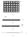
- a substrate comprises a base substrate, a metal black matrix and an anti-reflection pattern for reducing optical reflectivity of the metal black matrix, which are arranged on the base substrate, and the anti-reflection pattern being arranged on a side of the metal black matrix close to a light emission side of the substrate.
Abstract
Description
Claims (14)
Applications Claiming Priority (4)
| Application Number | Priority Date | Filing Date | Title |
|---|---|---|---|
| CN201510725238 | 2015-10-30 | ||
| CN201510725238.5A CN105204223B (en) | 2015-10-30 | 2015-10-30 | A kind of production method of substrate, substrate and display device |
| CN201510725238.5 | 2015-10-30 | ||
| PCT/CN2016/098347 WO2017071412A1 (en) | 2015-10-30 | 2016-09-07 | Substrate and method for fabrication thereof, and display device |
Publications (2)
| Publication Number | Publication Date |
|---|---|
| US20170276968A1 US20170276968A1 (en) | 2017-09-28 |
| US10197817B2 true US10197817B2 (en) | 2019-02-05 |
Family
ID=54951986
Family Applications (1)
| Application Number | Title | Priority Date | Filing Date |
|---|---|---|---|
| US15/507,122 Active US10197817B2 (en) | 2015-10-30 | 2016-09-07 | Substrate and manufacturing method thereof, and display device |
Country Status (3)
| Country | Link |
|---|---|
| US (1) | US10197817B2 (en) |
| CN (1) | CN105204223B (en) |
| WO (1) | WO2017071412A1 (en) |
Cited By (2)
| Publication number | Priority date | Publication date | Assignee | Title |
|---|---|---|---|---|
| US10324553B2 (en) * | 2015-05-12 | 2019-06-18 | Boe Technology Group Co., Ltd. | Array substrate and fabrication method thereof, optical touch screen, and display device |
| CN112582572A (en) * | 2020-12-09 | 2021-03-30 | 昆山工研院新型平板显示技术中心有限公司 | Display panel, touch display screen and electronic equipment |
Families Citing this family (7)
| Publication number | Priority date | Publication date | Assignee | Title |
|---|---|---|---|---|
| CN105204223B (en) | 2015-10-30 | 2019-05-03 | 京东方科技集团股份有限公司 | A kind of production method of substrate, substrate and display device |
| CN105824475B (en) | 2016-03-31 | 2019-11-26 | 京东方科技集团股份有限公司 | A kind of preparation method of display panel, display device and display panel |
| CN106054440B (en) * | 2016-07-25 | 2019-04-26 | 京东方科技集团股份有限公司 | A kind of array substrate and preparation method thereof and display device |
| CN106292102A (en) * | 2016-08-12 | 2017-01-04 | 京东方科技集团股份有限公司 | A kind of display floater and display |
| CN106505158B (en) * | 2016-12-01 | 2019-07-09 | Tcl集团股份有限公司 | A kind of light emitting diode with quantum dots device and preparation method thereof |
| CN107145001B (en) * | 2017-07-06 | 2020-03-27 | 京东方科技集团股份有限公司 | Touch display panel, manufacturing method thereof and display device |
| CN111047971A (en) * | 2019-11-26 | 2020-04-21 | Tcl华星光电技术有限公司 | Display panel and electronic device |
Citations (18)
| Publication number | Priority date | Publication date | Assignee | Title |
|---|---|---|---|---|
| US20010048490A1 (en) | 2000-05-25 | 2001-12-06 | Lim Byoung Ho | Liquid crystal display device and method for manufacturing the same |
| US20030116765A1 (en) * | 2001-12-26 | 2003-06-26 | Samsung Sdi, Co., Ltd. | Flat panel display device with anti-reflection layer having concentration gradient and fabrication method thereof |
| KR20040059647A (en) | 2002-12-28 | 2004-07-06 | 엘지.필립스 엘시디 주식회사 | Liquid crystal display device |
| CN201097055Y (en) | 2007-06-26 | 2008-08-06 | 上海广电光电子有限公司 | LCD device based on multi-vertical direction mode |
| CN101329465A (en) | 2008-05-30 | 2008-12-24 | 上海广电光电子有限公司 | Color membrane substrates and manufacturing method thereof |
| US20100055397A1 (en) * | 2006-11-15 | 2010-03-04 | National Institute Of Advanced Industrial Science And Technology | Mold for optical device with anti-reflection structure, method for producing the same, and optical device |
| US20110164210A1 (en) * | 2008-09-25 | 2011-07-07 | Kazuhiko Tsuda | Display device |
| US20130043477A1 (en) * | 2011-08-19 | 2013-02-21 | Doo-Hee JANG | Array substrate for liquid crystal display device and method of manufacturing the same |
| CN103353699A (en) | 2013-06-24 | 2013-10-16 | 京东方科技集团股份有限公司 | Array substrate, preparation method thereof and display device |
| CN104317097A (en) | 2014-10-31 | 2015-01-28 | 京东方科技集团股份有限公司 | COA (color filter on array) substrate, production method thereof and display device |
| CN104749816A (en) | 2015-04-14 | 2015-07-01 | 京东方科技集团股份有限公司 | Manufacturing method of display substrate, display substrate and display device |
| CN104794999A (en) | 2015-03-26 | 2015-07-22 | 友达光电股份有限公司 | Display panel |
| CN105093654A (en) | 2015-08-27 | 2015-11-25 | 京东方科技集团股份有限公司 | Array substrate, manufacturing method thereof and display device |
| US20150362776A1 (en) * | 2014-06-13 | 2015-12-17 | Semiconductor Energy Laboratory Co., Ltd. | Display Device |
| CN105204223A (en) | 2015-10-30 | 2015-12-30 | 京东方科技集团股份有限公司 | Production method of substrate, substrate and display apparatus |
| US20160052227A1 (en) * | 2013-04-05 | 2016-02-25 | Mitsubishi Rayon Co., Ltd. | Microrelief structural body, decorative sheet, decorative resin molded body, method for producing microrelief structural body, and method for producing decorative resin molded body |
| US20160254483A1 (en) * | 2014-07-02 | 2016-09-01 | Boe Technology Group Co., Ltd. | Active-matrix organic light-emitting diode (amoled) display panel, manufacturing method thereof and display device |
| US9841858B2 (en) * | 2014-07-07 | 2017-12-12 | Lg Innotek Co., Ltd. | Touch window |
Family Cites Families (3)
| Publication number | Priority date | Publication date | Assignee | Title |
|---|---|---|---|---|
| US20110016421A1 (en) * | 2009-07-20 | 2011-01-20 | Microsoft Corporation | Task oriented user interface platform |
| JP2013032835A (en) * | 2011-06-30 | 2013-02-14 | Nippon Densan Corp | Fan |
| KR102034073B1 (en) * | 2013-04-30 | 2019-10-18 | 도판 인사츠 가부시키가이샤 | Substrate for display devices, method for producing substrate for display devices, and display device |
-
2015
- 2015-10-30 CN CN201510725238.5A patent/CN105204223B/en active Active
-
2016
- 2016-09-07 US US15/507,122 patent/US10197817B2/en active Active
- 2016-09-07 WO PCT/CN2016/098347 patent/WO2017071412A1/en active Application Filing
Patent Citations (19)
| Publication number | Priority date | Publication date | Assignee | Title |
|---|---|---|---|---|
| US20010048490A1 (en) | 2000-05-25 | 2001-12-06 | Lim Byoung Ho | Liquid crystal display device and method for manufacturing the same |
| US20030116765A1 (en) * | 2001-12-26 | 2003-06-26 | Samsung Sdi, Co., Ltd. | Flat panel display device with anti-reflection layer having concentration gradient and fabrication method thereof |
| KR20040059647A (en) | 2002-12-28 | 2004-07-06 | 엘지.필립스 엘시디 주식회사 | Liquid crystal display device |
| US20100055397A1 (en) * | 2006-11-15 | 2010-03-04 | National Institute Of Advanced Industrial Science And Technology | Mold for optical device with anti-reflection structure, method for producing the same, and optical device |
| CN201097055Y (en) | 2007-06-26 | 2008-08-06 | 上海广电光电子有限公司 | LCD device based on multi-vertical direction mode |
| CN101329465A (en) | 2008-05-30 | 2008-12-24 | 上海广电光电子有限公司 | Color membrane substrates and manufacturing method thereof |
| US20110164210A1 (en) * | 2008-09-25 | 2011-07-07 | Kazuhiko Tsuda | Display device |
| US20130043477A1 (en) * | 2011-08-19 | 2013-02-21 | Doo-Hee JANG | Array substrate for liquid crystal display device and method of manufacturing the same |
| US20160052227A1 (en) * | 2013-04-05 | 2016-02-25 | Mitsubishi Rayon Co., Ltd. | Microrelief structural body, decorative sheet, decorative resin molded body, method for producing microrelief structural body, and method for producing decorative resin molded body |
| CN103353699A (en) | 2013-06-24 | 2013-10-16 | 京东方科技集团股份有限公司 | Array substrate, preparation method thereof and display device |
| US20160195751A1 (en) | 2013-06-24 | 2016-07-07 | BOE Technology Group Co.,Ltd. | Array substrate and manufacturing method thereof, and display device |
| US20150362776A1 (en) * | 2014-06-13 | 2015-12-17 | Semiconductor Energy Laboratory Co., Ltd. | Display Device |
| US20160254483A1 (en) * | 2014-07-02 | 2016-09-01 | Boe Technology Group Co., Ltd. | Active-matrix organic light-emitting diode (amoled) display panel, manufacturing method thereof and display device |
| US9841858B2 (en) * | 2014-07-07 | 2017-12-12 | Lg Innotek Co., Ltd. | Touch window |
| CN104317097A (en) | 2014-10-31 | 2015-01-28 | 京东方科技集团股份有限公司 | COA (color filter on array) substrate, production method thereof and display device |
| CN104794999A (en) | 2015-03-26 | 2015-07-22 | 友达光电股份有限公司 | Display panel |
| CN104749816A (en) | 2015-04-14 | 2015-07-01 | 京东方科技集团股份有限公司 | Manufacturing method of display substrate, display substrate and display device |
| CN105093654A (en) | 2015-08-27 | 2015-11-25 | 京东方科技集团股份有限公司 | Array substrate, manufacturing method thereof and display device |
| CN105204223A (en) | 2015-10-30 | 2015-12-30 | 京东方科技集团股份有限公司 | Production method of substrate, substrate and display apparatus |
Non-Patent Citations (2)
| Title |
|---|
| International Search Report and Written Opinion dated Dec. 1, 2016; PCT/CN2016/098347. |
| The First Chinese Office Action dated Sep. 30, 2017; Appln. 201510725238.5. |
Cited By (3)
| Publication number | Priority date | Publication date | Assignee | Title |
|---|---|---|---|---|
| US10324553B2 (en) * | 2015-05-12 | 2019-06-18 | Boe Technology Group Co., Ltd. | Array substrate and fabrication method thereof, optical touch screen, and display device |
| CN112582572A (en) * | 2020-12-09 | 2021-03-30 | 昆山工研院新型平板显示技术中心有限公司 | Display panel, touch display screen and electronic equipment |
| CN112582572B (en) * | 2020-12-09 | 2022-09-23 | 昆山工研院新型平板显示技术中心有限公司 | Display panel, touch display screen and electronic equipment |
Also Published As
| Publication number | Publication date |
|---|---|
| CN105204223B (en) | 2019-05-03 |
| WO2017071412A1 (en) | 2017-05-04 |
| CN105204223A (en) | 2015-12-30 |
| US20170276968A1 (en) | 2017-09-28 |
Similar Documents
| Publication | Publication Date | Title |
|---|---|---|
| US10197817B2 (en) | Substrate and manufacturing method thereof, and display device | |
| US10502994B2 (en) | Color filter on array substrate and fabricating method thereof as well as a display device | |
| US9958747B2 (en) | Array substrate and manufacturing method thereof, display panel and display device | |
| US9437487B2 (en) | Array substrate and fabrication method thereof, and display device | |
| US20190189639A1 (en) | Substrate and manufacturing method thereof and display device | |
| US20170125725A1 (en) | Organic Light Emitting Display Device and Method of Fabricating the Same | |
| US11309358B2 (en) | Display substrate and manufacturing method thereof | |
| US20200043996A1 (en) | Display substrate and display apparatus | |
| US20160334682A1 (en) | Color Filter on Array Substrate and Method for Manufacturing the same, as well as Display Device | |
| US9508867B2 (en) | Thin film transistor, array substrate, method of fabricating same, and display device | |
| KR20160124314A (en) | Display device and manufacturing method thereof | |
| US10290822B2 (en) | Thin film transistor including recessed gate insulation layer and its manufacturing method, array substrate, and display device | |
| US20180292926A1 (en) | Touch display panel and method for manufacturing the same | |
| US8120028B2 (en) | Active device array substrate, color filter substrate and manufacturing methods thereof | |
| US9070599B2 (en) | Array substrate, manufacturing method thereof and display device | |
| US10770488B2 (en) | Active switch array substrate and method for manufacturing the same | |
| US20160329361A1 (en) | Pixel structure, manufacturing method thereof and display panel | |
| US9791755B2 (en) | Color filter-on-array substrate, display device, and method for manufacturing the color filter-on-array substrate | |
| WO2016169305A1 (en) | Display substrate and manufacturing method therefor as well as display panel and display device | |
| WO2020232915A1 (en) | Display panel and manufacturing method therefor, and smart terminal | |
| WO2023092687A1 (en) | Display panel and manufacturing method therefor, and mobile terminal | |
| US9799683B2 (en) | Array substrate, preparation method thereof and display device | |
| US11209709B2 (en) | Display substrate and manufacturing method thereof, display panel and display device | |
| US20180188626A1 (en) | Display panel, method of manufacturing the same, and display using the same | |
| US10090338B2 (en) | Method for manufacturing array substrate, array substrate and display device |
Legal Events
| Date | Code | Title | Description |
|---|---|---|---|
| AS | Assignment |
Owner name: BEIJING BOE DISPLAY TECHNOLOGY CO., LTD., CHINA Free format text: ASSIGNMENT OF ASSIGNORS INTEREST;ASSIGNOR:BAI, JINCHAO;REEL/FRAME:041386/0510 Effective date: 20170113 Owner name: BOE TECHNOLOGY GROUP CO., LTD., CHINA Free format text: ASSIGNMENT OF ASSIGNORS INTEREST;ASSIGNOR:BAI, JINCHAO;REEL/FRAME:041386/0510 Effective date: 20170113 Owner name: BEIJING BOE DISPLAY TECHNOLOGY CO., LTD., CHINA Free format text: ASSIGNMENT OF ASSIGNORS INTEREST;ASSIGNOR:GUO, HUIBIN;REEL/FRAME:041386/0649 Effective date: 20170113 Owner name: BEIJING BOE DISPLAY TECHNOLOGY CO., LTD., CHINA Free format text: ASSIGNMENT OF ASSIGNORS INTEREST;ASSIGNOR:LIU, YAO;REEL/FRAME:041386/0570 Effective date: 20170113 Owner name: BOE TECHNOLOGY GROUP CO., LTD., CHINA Free format text: ASSIGNMENT OF ASSIGNORS INTEREST;ASSIGNOR:GUO, HUIBIN;REEL/FRAME:041386/0649 Effective date: 20170113 Owner name: BOE TECHNOLOGY GROUP CO., LTD., CHINA Free format text: ASSIGNMENT OF ASSIGNORS INTEREST;ASSIGNOR:LIU, YAO;REEL/FRAME:041386/0570 Effective date: 20170113 |
|
| STCF | Information on status: patent grant |
Free format text: PATENTED CASE |
|
| MAFP | Maintenance fee payment |
Free format text: PAYMENT OF MAINTENANCE FEE, 4TH YEAR, LARGE ENTITY (ORIGINAL EVENT CODE: M1551); ENTITY STATUS OF PATENT OWNER: LARGE ENTITY Year of fee payment: 4 |