US10186729B2 - Battery cell compression method and assembly - Google Patents
Battery cell compression method and assembly Download PDFInfo
- Publication number
- US10186729B2 US10186729B2 US15/462,006 US201715462006A US10186729B2 US 10186729 B2 US10186729 B2 US 10186729B2 US 201715462006 A US201715462006 A US 201715462006A US 10186729 B2 US10186729 B2 US 10186729B2
- Authority
- US
- United States
- Prior art keywords
- battery cells
- curable material
- fixture
- plate
- winding
- Prior art date
- Legal status (The legal status is an assumption and is not a legal conclusion. Google has not performed a legal analysis and makes no representation as to the accuracy of the status listed.)
- Active, expires
Links
- 238000000034 method Methods 0.000 title claims abstract description 35
- 230000006835 compression Effects 0.000 title description 38
- 238000007906 compression Methods 0.000 title description 38
- 239000000463 material Substances 0.000 claims abstract description 78
- 238000004804 winding Methods 0.000 claims abstract description 38
- 230000008878 coupling Effects 0.000 claims description 8
- 238000010168 coupling process Methods 0.000 claims description 8
- 238000005859 coupling reaction Methods 0.000 claims description 8
- 229920000642 polymer Polymers 0.000 claims description 7
- 229920002430 Fibre-reinforced plastic Polymers 0.000 claims description 2
- 239000011151 fibre-reinforced plastic Substances 0.000 claims description 2
- 238000012546 transfer Methods 0.000 description 13
- 238000003491 array Methods 0.000 description 9
- 230000000712 assembly Effects 0.000 description 4
- 238000000429 assembly Methods 0.000 description 4
- 239000000835 fiber Substances 0.000 description 4
- 229910000831 Steel Inorganic materials 0.000 description 2
- 238000002485 combustion reaction Methods 0.000 description 2
- 239000002826 coolant Substances 0.000 description 2
- 238000013461 design Methods 0.000 description 2
- 239000000446 fuel Substances 0.000 description 2
- 229910052751 metal Inorganic materials 0.000 description 2
- 239000002184 metal Substances 0.000 description 2
- 239000010959 steel Substances 0.000 description 2
- 229920000049 Carbon (fiber) Polymers 0.000 description 1
- 229910052782 aluminium Inorganic materials 0.000 description 1
- XAGFODPZIPBFFR-UHFFFAOYSA-N aluminium Chemical compound [Al] XAGFODPZIPBFFR-UHFFFAOYSA-N 0.000 description 1
- 239000004760 aramid Substances 0.000 description 1
- 229920006231 aramid fiber Polymers 0.000 description 1
- 238000005452 bending Methods 0.000 description 1
- 230000005540 biological transmission Effects 0.000 description 1
- 239000004917 carbon fiber Substances 0.000 description 1
- 239000013256 coordination polymer Substances 0.000 description 1
- 239000012530 fluid Substances 0.000 description 1
- 239000011521 glass Substances 0.000 description 1
- 230000002452 interceptive effect Effects 0.000 description 1
- 229910001416 lithium ion Inorganic materials 0.000 description 1
- 229910001092 metal group alloy Inorganic materials 0.000 description 1
- 238000012986 modification Methods 0.000 description 1
- 230000004048 modification Effects 0.000 description 1
- 230000001172 regenerating effect Effects 0.000 description 1
- 238000013022 venting Methods 0.000 description 1
Images


Classifications
-
- H—ELECTRICITY
- H01—ELECTRIC ELEMENTS
- H01M—PROCESSES OR MEANS, e.g. BATTERIES, FOR THE DIRECT CONVERSION OF CHEMICAL ENERGY INTO ELECTRICAL ENERGY
- H01M10/00—Secondary cells; Manufacture thereof
- H01M10/04—Construction or manufacture in general
- H01M10/0481—Compression means other than compression means for stacks of electrodes and separators
-
- H01M2/0262—
-
- H01M2/0267—
-
- H01M2/1077—
-
- H—ELECTRICITY
- H01—ELECTRIC ELEMENTS
- H01M—PROCESSES OR MEANS, e.g. BATTERIES, FOR THE DIRECT CONVERSION OF CHEMICAL ENERGY INTO ELECTRICAL ENERGY
- H01M50/00—Constructional details or processes of manufacture of the non-active parts of electrochemical cells other than fuel cells, e.g. hybrid cells
- H01M50/20—Mountings; Secondary casings or frames; Racks, modules or packs; Suspension devices; Shock absorbers; Transport or carrying devices; Holders
- H01M50/218—Mountings; Secondary casings or frames; Racks, modules or packs; Suspension devices; Shock absorbers; Transport or carrying devices; Holders characterised by the material
- H01M50/22—Mountings; Secondary casings or frames; Racks, modules or packs; Suspension devices; Shock absorbers; Transport or carrying devices; Holders characterised by the material of the casings or racks
- H01M50/227—Organic material
-
- H—ELECTRICITY
- H01—ELECTRIC ELEMENTS
- H01M—PROCESSES OR MEANS, e.g. BATTERIES, FOR THE DIRECT CONVERSION OF CHEMICAL ENERGY INTO ELECTRICAL ENERGY
- H01M50/00—Constructional details or processes of manufacture of the non-active parts of electrochemical cells other than fuel cells, e.g. hybrid cells
- H01M50/20—Mountings; Secondary casings or frames; Racks, modules or packs; Suspension devices; Shock absorbers; Transport or carrying devices; Holders
- H01M50/249—Mountings; Secondary casings or frames; Racks, modules or packs; Suspension devices; Shock absorbers; Transport or carrying devices; Holders specially adapted for aircraft or vehicles, e.g. cars or trains
-
- H—ELECTRICITY
- H01—ELECTRIC ELEMENTS
- H01M—PROCESSES OR MEANS, e.g. BATTERIES, FOR THE DIRECT CONVERSION OF CHEMICAL ENERGY INTO ELECTRICAL ENERGY
- H01M50/00—Constructional details or processes of manufacture of the non-active parts of electrochemical cells other than fuel cells, e.g. hybrid cells
- H01M50/20—Mountings; Secondary casings or frames; Racks, modules or packs; Suspension devices; Shock absorbers; Transport or carrying devices; Holders
- H01M50/262—Mountings; Secondary casings or frames; Racks, modules or packs; Suspension devices; Shock absorbers; Transport or carrying devices; Holders with fastening means, e.g. locks
- H01M50/264—Mountings; Secondary casings or frames; Racks, modules or packs; Suspension devices; Shock absorbers; Transport or carrying devices; Holders with fastening means, e.g. locks for cells or batteries, e.g. straps, tie rods or peripheral frames
-
- H—ELECTRICITY
- H01—ELECTRIC ELEMENTS
- H01M—PROCESSES OR MEANS, e.g. BATTERIES, FOR THE DIRECT CONVERSION OF CHEMICAL ENERGY INTO ELECTRICAL ENERGY
- H01M2220/00—Batteries for particular applications
- H01M2220/20—Batteries in motive systems, e.g. vehicle, ship, plane
-
- H—ELECTRICITY
- H01—ELECTRIC ELEMENTS
- H01M—PROCESSES OR MEANS, e.g. BATTERIES, FOR THE DIRECT CONVERSION OF CHEMICAL ENERGY INTO ELECTRICAL ENERGY
- H01M50/00—Constructional details or processes of manufacture of the non-active parts of electrochemical cells other than fuel cells, e.g. hybrid cells
- H01M50/10—Primary casings; Jackets or wrappings
- H01M50/102—Primary casings; Jackets or wrappings characterised by their shape or physical structure
- H01M50/103—Primary casings; Jackets or wrappings characterised by their shape or physical structure prismatic or rectangular
-
- Y—GENERAL TAGGING OF NEW TECHNOLOGICAL DEVELOPMENTS; GENERAL TAGGING OF CROSS-SECTIONAL TECHNOLOGIES SPANNING OVER SEVERAL SECTIONS OF THE IPC; TECHNICAL SUBJECTS COVERED BY FORMER USPC CROSS-REFERENCE ART COLLECTIONS [XRACs] AND DIGESTS
- Y02—TECHNOLOGIES OR APPLICATIONS FOR MITIGATION OR ADAPTATION AGAINST CLIMATE CHANGE
- Y02E—REDUCTION OF GREENHOUSE GAS [GHG] EMISSIONS, RELATED TO ENERGY GENERATION, TRANSMISSION OR DISTRIBUTION
- Y02E60/00—Enabling technologies; Technologies with a potential or indirect contribution to GHG emissions mitigation
- Y02E60/10—Energy storage using batteries
-
- Y—GENERAL TAGGING OF NEW TECHNOLOGICAL DEVELOPMENTS; GENERAL TAGGING OF CROSS-SECTIONAL TECHNOLOGIES SPANNING OVER SEVERAL SECTIONS OF THE IPC; TECHNICAL SUBJECTS COVERED BY FORMER USPC CROSS-REFERENCE ART COLLECTIONS [XRACs] AND DIGESTS
- Y02—TECHNOLOGIES OR APPLICATIONS FOR MITIGATION OR ADAPTATION AGAINST CLIMATE CHANGE
- Y02P—CLIMATE CHANGE MITIGATION TECHNOLOGIES IN THE PRODUCTION OR PROCESSING OF GOODS
- Y02P70/00—Climate change mitigation technologies in the production process for final industrial or consumer products
- Y02P70/50—Manufacturing or production processes characterised by the final manufactured product
Definitions
- This disclosure relates generally to a battery array and, more particularly, to a curable material at least partially wound around battery cells of the battery array.
- Electrified vehicles differ from conventional motor vehicles because electrified vehicles are selectively driven using one or more electric machines powered by a traction battery pack.
- the electric machines can drive the electrified vehicles instead of, or in addition to, an internal combustion engine.
- Example electrified vehicles include hybrid electric vehicles (HEVs), plug-in hybrid electric vehicles (PHEVs), fuel cell vehicles (FCVs), and battery electric vehicles (BEVs).
- HEVs hybrid electric vehicles
- PHEVs plug-in hybrid electric vehicles
- FCVs fuel cell vehicles
- BEVs battery electric vehicles
- a traction battery pack of an electrified vehicle can include one or more battery arrays. Plates, such as end plates and side plates, are positioned about the battery cells of the arrays. Tensioning rods, or other bracing features, pull opposing plates together to compress the battery cells, which can expand over time.
- the plates are typically metal.
- a method according to an exemplary aspect of the present disclosure includes, among other things, winding a curable material at least partially about a plurality of battery cells that are compressed by a fixture.
- the method includes, after the curable material has cured, holding the plurality of battery cells in a compressed position using the curable material rather than the fixture.
- a further non-limiting embodiment of any of the foregoing methods includes winding the curable material about an entire circumferential perimeter of the plurality of battery cells.
- a further non-limiting embodiment of any of the foregoing methods includes compressing the plurality of battery cells prior to the winding by moving a first plate toward a second plate using the fixture.
- the plurality of battery cells are positioned between the first and second plates.
- the fixture is coupled to the first and the second plate when the fixture is compressing the plurality of battery cells, and is decoupled from the first plate and the second plate after the curable material has cured.
- the fixture is coupled to respective coupling surfaces of the first and the second plate when the fixture is coupled to the first and the second plate, and the winding includes winding the curable material about winding surfaces of the first and second plate.
- the winding surfaces are transverse to the coupling surfaces.
- a further non-limiting embodiment of any of the foregoing methods includes using an actuator to adjust the fixture to a position where the plurality of battery cells are compressed by the fixture, and decoupling the fixture from the actuator while the plurality of battery cells are compressed by the fixture.
- the curable material is a fiber-reinforced polymer-based tape.
- a further non-limiting embodiment of any of the foregoing methods includes winding the curable material at least three times about a perimeter of the plurality of battery cells.
- a further non-limiting embodiment of any of the foregoing methods includes winding the curable material about the plurality of battery cells and about a thermal exchange plate such that the curable material holds the thermal exchange plate relative to the plurality of battery cells after the curable material has cured.
- the plurality of battery cells are part of a traction battery pack.
- the winding includes rotating the plurality of battery cells relative to the curable material.
- the curable material is cured after the winding.
- a first amount of the curable material is wound about the battery cells to compress the battery cells between first and second plates, and a second amount of the curable material is wound about the battery cells to hold a device relative to the battery cells.
- the first amount of material is wound about a first axis.
- the second amount of material is wound about a second axis transverse to the first axis.
- An assembly includes, among other things, a plurality of battery cells compressed by a fixture, and a curable material wound around the plurality of battery cells.
- the assembly includes a first plate and a second plate.
- the fixture is coupled to the first and second plates to compress the battery cells between the first and second plates.
- the first plate and the second plate are a polymer-based material.
- the curable material is a tape that fiber-reinforced and polymer-based.
- the curable material includes at least one layer of the tape.
- the plurality of battery cells are part of a traction battery pack.
- FIG. 1 illustrates a schematic view of an example powertrain of an electrified vehicle.
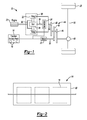
- FIG. 2 illustrates a side view of a traction battery pack from the powertrain of FIG. 1 .
- FIG. 3 illustrates a battery array from the traction battery pack of FIG. 2 that incorporates an exemplary compression assembly utilizing a curable material.
- FIG. 4 shows a section view at Line 4 - 4 in FIG. 3 .
- FIG. 5 shows a perspective view of a plate from the battery array of FIG. 3 .
- FIG. 6 shows plates of the battery array of FIG. 3 decoupled from a fixture.
- FIG. 7 shows the plates of FIG. 6 coupled to the fixture.
- FIG. 8 shows exemplary steps in the process of winding a curable material about the plates and the battery cells of FIG. 7 .
- FIG. 9 shows the flow of an exemplary method for winding a curable material around the battery cells of FIG. 7 .
- FIG. 10 shows a battery array incorporating a compression assembly as a curable material according to another exemplary embodiment.
- FIG. 11 shows exemplary steps in the process of winding a curable material about the plates and the battery cells according to still another exemplary embodiment.
- This disclosure relates to winding a curable material around battery cells.
- the battery cells are compressed as the curable material is wound.
- the material then cures to hold the battery cells in the compressed position.
- a powertrain 10 of a plug-in hybrid electric vehicle includes a traction battery pack 14 having a plurality of battery arrays 18 , an internal combustion engine 20 , a motor 22 , and a generator 24 .
- the motor 22 and the generator 24 are types of electric machines.
- the motor 22 and generator 24 may be separate or have the form of a combined motor-generator.
- PHEV PHEV
- HEVs hybrid electric vehicles
- BEVs battery electric vehicles
- fuel cell vehicles etc.
- the powertrain 10 is a power-split powertrain that employs a first drive system and a second drive system.
- the first and second drive systems generate torque to drive one or more sets of vehicle drive wheels 28 .
- the first drive system includes a combination of the engine 20 and the generator 24 .
- the second drive system includes at least the motor 22 , the generator 24 , and the traction battery pack 14 .
- the motor 22 and the generator 24 are portions of an electric drive system of the powertrain 10 .
- the engine 20 and the generator 24 can be connected through a power transfer unit 30 , such as a planetary gear set.
- a power transfer unit 30 such as a planetary gear set.
- the power transfer unit 30 is a planetary gear set that includes a ring gear 32 , a sun gear 34 , and a carrier assembly 36 .
- the generator 24 can be driven by the engine 20 through the power transfer unit 30 to convert kinetic energy to electrical energy.
- the generator 24 can alternatively function as a motor to convert electrical energy into kinetic energy, thereby outputting torque to a shaft 38 connected to the power transfer unit 30 .
- the ring gear 32 of the power transfer unit 30 is connected to a shaft 40 , which is connected to the vehicle drive wheels 28 through a second power transfer unit 44 .
- the second power transfer unit 44 may include a gear set having a plurality of gears 46 .
- Other power transfer units could be used in other examples.
- the gears 46 transfer torque from the engine 20 to a differential 48 to ultimately provide traction to the vehicle drive wheels 28 .
- the differential 48 may include a plurality of gears that enable the transfer of torque to the vehicle drive wheels 28 .
- the second power transfer unit 44 is mechanically coupled to an axle 50 through the differential 48 to distribute torque to the vehicle drive wheels 28 .
- the motor 22 can be selectively employed to drive the vehicle drive wheels 28 by outputting torque to a shaft 54 that is also connected to the second power transfer unit 44 .
- the motor 22 and the generator 24 cooperate as part of a regenerative braking system in which both the motor 22 and the generator 24 can be employed as motors to output torque.
- the motor 22 and the generator 24 can each output electrical power to recharge cells of the traction battery pack 14 .
- the traction battery pack 14 in an exemplary non-limiting embodiment, includes an enclosure 60 housing three of the battery arrays 18 .
- the enclosure 60 could house fewer than three battery arrays 18 , or more than three battery arrays 18 .
- the battery arrays 18 include a plurality of battery cells 64 , a first plate 68 , a second plate 72 , a compression assembly 76 , and a base 78 .
- the battery cells 64 are distributed along an axis A. Separators (not shown) could be positioned between axially adjacent battery cells 64 within the battery arrays 18 .
- the battery cells 64 are lithium ion cells in this example, which, if unconstrained, can expand over time. Specifically, in this example, the battery cells 64 are prismatic cells. In other examples, the battery cells 64 could be pouch type cells, cylindrical cells, or some other type of battery cell.
- the first plate 68 is at a first end of the battery cells 64 .
- the second plate 72 is at an opposing, second end of the battery cells 64 .
- the battery cells 64 are compressed axially between the plates 68 and 72 . Expansion of the battery cells 64 is thus constrained at each axial end by the plates 68 and 72 .
- the compression assembly 76 holds the first plate 68 and the second plate 72 axially in a position suitable for compressing the battery cells 64 .
- the compression assembly 76 , the first plate 68 , the second plate 72 , and the battery cells 64 are disposed upon the base 78 .
- the base 78 is a thermal exchange plate that communicates a coolant utilized to cool the battery cells 64 .
- the base 78 in this example, is disposed at a vertical bottom of the battery cells 64 .
- Terminals 80 extend from the battery cells 64 at a vertical top opposite the end of the battery cells 64 interfacing with the base 78 .
- the compression assembly 76 is a multilayered structure including multiple layers of a curable material.
- the curable material is a fiber reinforced, polymer-based tape 84 .
- the exemplary fiber of the tape 84 could comprise glass filaments or fibers, carbon fibers, aramid fibers, etc., which are distributed within a polymer-based material.
- the fibers are substantially non-conductive in this example.
- the curable material of the compression assembly 76 is cured to a desired state after being positioned about battery cells 64 .
- Some battery cells 64 cannot be stored above certain temperatures, say 60 degrees Celsius. Accordingly, the material of the compression assembly 76 is, in such examples, a material that can cure without requiring its temperature to be elevated to temperatures that could impact the battery cells 64 .
- the compression assembly 76 is formed utilizing approximately three layers of the tape 84 wound around the battery cells 64 .
- the number of layers of the tape 84 need not be consistent throughout the compression assembly 76 .
- a portion of the tape 84 could overlap two other layers, and another portion of the tape 84 could overlap three layers for example.
- the example tape 84 is wound about an entire circumferential perimeter of the battery cells 64 in this example.
- the example tape 84 is additionally wound about the plates 68 , 72 .
- the tape 84 interfaces with winding surfaces 86 a and 86 b of the plates 68 , 72 .
- the winding surfaces 86 a face in the direction of the axis A.
- the winding surfaces 86 b face laterally away from the axis A.
- Winding the tape 84 about the plates 68 , 72 at the axial ends of the battery cells 64 distributes the tensioning load from the tape 84 across the plates 68 , 72 . This can prevent the tape 84 from compressing the battery cells 64 at the axial ends, particularly across the corners C BC of the battery cells 64 .
- the plates 68 , 72 are a metal or metal alloy.
- the plates 68 , 72 could be extruded aluminum.
- the plates 68 , 72 are polymer-based, which can provide some weight savings. Corners C P ( FIG. 5 ) of the plates 68 , 72 can have a radius to facilitate bending the tape 84 about the corners C P without overly stressing an area of the tape 84 .
- exemplary compression assembly 76 is wound about the battery cells 64 and the plates 68 , 72
- other exemplary embodiments could include a compression assembly 76 wound about the battery cells 64 , but not the plates 68 , 72 .
- the tape 84 is permitted to cure.
- the tape 84 when cured, provides the compression assembly 76 , which holds the axial position of the first plate 68 and the second plate 72 , and additionally protects the axial ends and laterally facing sides of the battery array 18 .
- the tape 84 effectively compresses the battery cells 64 so that no tensioning rods or similar bracing features are required.
- the tape 84 in this exemplary non-limiting embodiment, has a width W which is less than a height H of the first plate 68 , the second plate 72 , and the battery cells 64 .
- the tape 84 is thus wound about the outer periphery of the plates 68 , 72 , and the battery cells 64 multiple times in order to ensure that layers of the tape 84 extend the full height H of the plates 68 , 72 , and battery cells 64 .
- the battery cells 64 are compressed axially between the plates 68 , 72 as the tape 84 as the tape 84 is applied.
- the plates 68 , 72 include a pair of bores 88 opening to a coupling surface 90 of the plates 68 , 72 .
- the coupling surface 90 is transverse, and in this example perpendicular, to the winding surfaces 86 a and 86 b.
- the bores 88 provide an interface to couple the plates 68 , 72 to a fixture 92 .
- the fixture 92 is used to compress the battery cells 64 along the axis A between the plates 68 , 72 so that the tape 84 can be applied with the battery cells 64 in a desired compressed position.
- the fixture 92 includes pins 96 received within the bores 88 to couple the plates 68 , 72 to the fixture 92 .
- the fixture 92 is removeably mounted upon an actuator 98 .
- the actuator 98 manipulates the pins 96 between positions that are axially closer to each other, and positions that are axially further from each other.
- the actuator 98 could have many forms, including, but not limited to, a hydraulic actuator, a pneumatic actuator, or a rack-and-pinion type configuration.
- the actuator 98 can manipulate the fixture to a position causing the fixture to draw the plates 68 , 72 closer together, which compresses the battery cells 64 axially.
- the fixture 92 can then be locked in the position compressing the battery cells 64 and disengaged from an actuator 98 .
- the battery cells 64 , and the plates 68 , 72 are then transitioned to a wrapping stage where the curable material is applied that will cure to form the compression assembly 76 of FIG. 3 .
- the battery cells 64 and the plates 68 are compressed axially by the fixture 92 , which has been detached from the actuator 98 .
- the fixture 92 thus keeps the battery cells 64 compressed even when the fixture 92 is detached from the actuator 98 .
- the battery cells 64 with the plates 68 , 72 are rotated in a direction R relative to a roll of the tape 84 .
- the battery cells 64 and plates 68 , 72 thus act as a mandrel.
- the tape 84 can be rotated relative to the battery cells 64 and the plates 68 , 72
- the rotation in the direction R causes the tape 84 to wrap about the battery cells 64 and the plates 68 and 72 .
- the wrapping of the tape 84 continues until the compression assembly 76 has a desired thickness. Again, the fixture 92 keeps the battery cells 64 and the plates 68 , 72 compressed axially during the wrapping.
- the battery cells 64 with the plates 68 and 72 can be tipped relative to the tape 84 as the tape 84 is applied to cause the tape 84 to adhere to the battery cells 64 and the plates 68 , 72 at an angle. That is, when applying, for example, the tape 84 to a side of the battery cells 64 , the battery cells 64 can be tipped so that the tape 84 is applied in a way that extends the tape 84 from a vertical bottom at a first axial end of the battery cells 64 to a vertical top at an opposite axial end of the battery cells 64 . Angling the tape 84 in this way could help to withstand torsional loading of the battery array 18 .
- the compression assembly 76 is permitted time to cure while the fixture 92 continues to compress the battery cells 64 between the plates 68 , 72 . After curing, the tape can hold the axial position of the plates 68 , 72 . The fixture 92 can then be decoupled from the plates 68 , 72 . The battery cells 64 and the compression assembly 76 can then be positioned atop the base 78 .
- an exemplary method 100 of incorporating a compression assembly into a battery array includes a step 110 of coupling a fixture to a first plate and a second plate. Then, at a step 120 , the fixture is adjusted using an actuator to move the plates closer together. At the step 130 , battery cells are compressed between the plates that are moving closer together.
- a curable material is wound about the battery cells and the plates while the fixture continues to compress the battery cells between the plates.
- the curable material cures while the fixture continues to compress the battery cells between the plates.
- the fixture decouples from the plates. At this point, the curable material, which has now cured, can sufficiently hold the battery cells in the compressed position.
- another exemplary battery array 18 a suitable for use within the traction battery pack 14 of FIG. 1 includes a compression assembly 76 a similar in design to the compression assembly of FIG. 3 in that the compression assembly 76 a is formed of a curable material.
- the curable material has been wound around the base 78 a , as well as plates 68 a and 72 a , and battery cells 64 a.
- the compression assembly 76 a holds the base 78 a relative to the battery cells 64 a , in addition to holding the axial position of the plates 68 a and 72 a.
- a fixture compressing the battery cells 64 a during the winding can, for example, engage bores 88 a opening to an upwardly facing surface of the plates 68 a and 72 a . Coupling such a fixture to this side of the plate 68 a and 78 a can avoid the fixture interfering with the winding of the curable material about the base 78 a.
- the curable material of the compression assembly 76 a could additionally, or instead, be wound about the surfaces of the battery cells 64 a incorporating the terminals 80 b . These surfaces are vertically top surfaces in this example.
- the curable material could be wound in a way that avoids covering the terminals 80 b .
- the curable material could be cut away to reveal the terminals 80 b after the curable material has cured. Covering the vertically top surfaces of the battery cells 64 a can help to electrically isolate the battery cells 64 a.
- another exemplary battery array 18 b suitable for use within the traction battery pack 14 of FIG. 1 includes a compression assembly 76 b similar in design to the compression assembly of FIG. 3 in that the compression assembly 76 b is formed of a curable material.
- the curable material has been wound around the base 78 b , a busbar assembly 82 or module, as well as plates 68 b , 72 b , and battery cells 64 b.
- the compression assembly 76 b includes a first assembly 76 b ′ and a second assembly 76 b ′′.
- the first assembly 76 b ′ represents a first amount of a curable material
- the second assembly 76 b ′′ represents a second amount of a curable material.
- the first assembly 76 b ′ is wound around the plates 68 b , 72 b , and battery cells 64 b .
- the first assembly 76 b ′ is wound about an axis A′, which is transverse to the axis A.
- the battery cells 64 b are distributed along the axis A.
- the axis A′ is transverse to the axis A.
- the first assembly 76 b ′ is then permitted to fully cure or partially cure.
- a fixture such as the fixture 92 ( FIGS. 6 and 7 ) holding the plates 68 b , 72 b can then be decoupled.
- the base 78 b is a thermal exchange plate, in this example.
- the base 78 b includes coolant ports.
- the second assembly 76 b ′′ is then wound around the battery cells 64 b , the base 78 b , and the busbar assembly 82 .
- the second assembly 76 b ′′ is wound about the axis A, which is perpendicular to the axis A′.
- the second assembly 76 b ′′ when cured, holds the devices relative to the battery cells 64 b.
- a fixture 92 b can engage the plate 68 b to rotate the battery cells 64 b about the axis A.
- the curable material could move about the battery cells 64 b in another example.
- the compression assembly 76 b holds the base 78 b relative to the battery cells 64 b , in addition to holding the axial position of the plates 68 b and 72 b.
- the second assembly 76 b ′′ is applied when the first assembly 76 b ′ is partially cured, which can facilitate bonding the second assembly 76 b ′′ to the first assembly 76 b′.
- the spacing of the second assembly 76 b ′′ from the battery cells 64 b can provide a vent chamber used to communicate a fluid from the battery cells 64 b during a venting event.
- the busbar assembly 82 can block movement of the second assembly 76 b ′′ against the battery cells 64 b to provide the vent chamber, for example.
- the compression assembly can provide, among other things, sidewalls and endwalls of a battery array.
- the compression assembly can reduce an overall size of the array since fasteners and tensioning rods and other bracing features are not required.
- the plate size can also be reduced since the plates, among other things, do not interface with bracing features like tensioning rods.
- the plates are subject to the distributed loads of the compression assembly, but not the more focused point loads of such bracing features.
- the high tensile strength to weight ratio for the curable material verses, for example, steel, can permit the thickness of the compression assembly to be less than a steel sidewall providing protection and support.
Landscapes
- Chemical & Material Sciences (AREA)
- Chemical Kinetics & Catalysis (AREA)
- Electrochemistry (AREA)
- General Chemical & Material Sciences (AREA)
- Engineering & Computer Science (AREA)
- Aviation & Aerospace Engineering (AREA)
- Manufacturing & Machinery (AREA)
- Battery Mounting, Suspending (AREA)
Abstract
An exemplary method includes, among other things, winding a curable material at least partially about a plurality of battery cells that are compressed by a fixture. An exemplary assembly includes, among other things, a plurality of battery cells compressed by a fixture, and a curable material wound around the plurality of battery cells.
Description
This disclosure relates generally to a battery array and, more particularly, to a curable material at least partially wound around battery cells of the battery array.
Electrified vehicles differ from conventional motor vehicles because electrified vehicles are selectively driven using one or more electric machines powered by a traction battery pack. The electric machines can drive the electrified vehicles instead of, or in addition to, an internal combustion engine. Example electrified vehicles include hybrid electric vehicles (HEVs), plug-in hybrid electric vehicles (PHEVs), fuel cell vehicles (FCVs), and battery electric vehicles (BEVs).
A traction battery pack of an electrified vehicle can include one or more battery arrays. Plates, such as end plates and side plates, are positioned about the battery cells of the arrays. Tensioning rods, or other bracing features, pull opposing plates together to compress the battery cells, which can expand over time. The plates are typically metal.
A method according to an exemplary aspect of the present disclosure includes, among other things, winding a curable material at least partially about a plurality of battery cells that are compressed by a fixture.
In a further non-limiting embodiment of the foregoing method, the method includes, after the curable material has cured, holding the plurality of battery cells in a compressed position using the curable material rather than the fixture.
A further non-limiting embodiment of any of the foregoing methods includes winding the curable material about an entire circumferential perimeter of the plurality of battery cells.
A further non-limiting embodiment of any of the foregoing methods includes compressing the plurality of battery cells prior to the winding by moving a first plate toward a second plate using the fixture. The plurality of battery cells are positioned between the first and second plates.
In a further non-limiting embodiment of any of the foregoing methods, the fixture is coupled to the first and the second plate when the fixture is compressing the plurality of battery cells, and is decoupled from the first plate and the second plate after the curable material has cured.
In a further non-limiting embodiment of any of the foregoing methods, the fixture is coupled to respective coupling surfaces of the first and the second plate when the fixture is coupled to the first and the second plate, and the winding includes winding the curable material about winding surfaces of the first and second plate. The winding surfaces are transverse to the coupling surfaces.
A further non-limiting embodiment of any of the foregoing methods includes using an actuator to adjust the fixture to a position where the plurality of battery cells are compressed by the fixture, and decoupling the fixture from the actuator while the plurality of battery cells are compressed by the fixture.
In a further non-limiting embodiment of any of the foregoing methods, the curable material is a fiber-reinforced polymer-based tape.
A further non-limiting embodiment of any of the foregoing methods includes winding the curable material at least three times about a perimeter of the plurality of battery cells.
A further non-limiting embodiment of any of the foregoing methods includes winding the curable material about the plurality of battery cells and about a thermal exchange plate such that the curable material holds the thermal exchange plate relative to the plurality of battery cells after the curable material has cured.
In a further non-limiting embodiment of any of the foregoing methods, the plurality of battery cells are part of a traction battery pack.
In a further non-limiting embodiment of any of the foregoing methods, the winding includes rotating the plurality of battery cells relative to the curable material.
In a further non-limiting embodiment of any of the foregoing methods, the curable material is cured after the winding.
In a further non-limiting embodiment of any of the foregoing methods, a first amount of the curable material is wound about the battery cells to compress the battery cells between first and second plates, and a second amount of the curable material is wound about the battery cells to hold a device relative to the battery cells. The first amount of material is wound about a first axis. The second amount of material is wound about a second axis transverse to the first axis.
An assembly according to an exemplary aspect of the present disclosure includes, among other things, a plurality of battery cells compressed by a fixture, and a curable material wound around the plurality of battery cells.
In a further non-limiting embodiment of the foregoing assembly, the assembly includes a first plate and a second plate. The fixture is coupled to the first and second plates to compress the battery cells between the first and second plates.
In a further non-limiting embodiment of any of the foregoing assemblies, the first plate and the second plate are a polymer-based material.
In a further non-limiting embodiment of any of the foregoing assemblies, the curable material is a tape that fiber-reinforced and polymer-based.
In a further non-limiting embodiment of any of the foregoing assemblies, the curable material includes at least one layer of the tape.
In a further non-limiting embodiment of any of the foregoing assemblies, the plurality of battery cells are part of a traction battery pack.
The various features and advantages of the disclosed examples will become apparent to those skilled in the art from the detailed description. The figures that accompany the detailed description can be briefly described as follows:
This disclosure relates to winding a curable material around battery cells. The battery cells are compressed as the curable material is wound. The material then cures to hold the battery cells in the compressed position.
Referring to FIG. 1 , a powertrain 10 of a plug-in hybrid electric vehicle (PHEV) includes a traction battery pack 14 having a plurality of battery arrays 18, an internal combustion engine 20, a motor 22, and a generator 24. The motor 22 and the generator 24 are types of electric machines. The motor 22 and generator 24 may be separate or have the form of a combined motor-generator.
Although depicted as a PHEV, it should be understood that the concepts described herein are not limited to PHEVs and could extend to traction battery packs and battery arrays in any other type of electrified vehicle, including, but not limited to, other hybrid electric vehicles (HEVs), battery electric vehicles (BEVs), fuel cell vehicles, etc.
In this embodiment, the powertrain 10 is a power-split powertrain that employs a first drive system and a second drive system. The first and second drive systems generate torque to drive one or more sets of vehicle drive wheels 28. The first drive system includes a combination of the engine 20 and the generator 24. The second drive system includes at least the motor 22, the generator 24, and the traction battery pack 14. The motor 22 and the generator 24 are portions of an electric drive system of the powertrain 10.
The engine 20 and the generator 24 can be connected through a power transfer unit 30, such as a planetary gear set. Of course, other types of power transfer units, including other gear sets and transmissions, can be used to connect the engine 20 to the generator 24. In one non-limiting embodiment, the power transfer unit 30 is a planetary gear set that includes a ring gear 32, a sun gear 34, and a carrier assembly 36.
The generator 24 can be driven by the engine 20 through the power transfer unit 30 to convert kinetic energy to electrical energy. The generator 24 can alternatively function as a motor to convert electrical energy into kinetic energy, thereby outputting torque to a shaft 38 connected to the power transfer unit 30.
The ring gear 32 of the power transfer unit 30 is connected to a shaft 40, which is connected to the vehicle drive wheels 28 through a second power transfer unit 44. The second power transfer unit 44 may include a gear set having a plurality of gears 46. Other power transfer units could be used in other examples.
The gears 46 transfer torque from the engine 20 to a differential 48 to ultimately provide traction to the vehicle drive wheels 28. The differential 48 may include a plurality of gears that enable the transfer of torque to the vehicle drive wheels 28. In this example, the second power transfer unit 44 is mechanically coupled to an axle 50 through the differential 48 to distribute torque to the vehicle drive wheels 28.
The motor 22 can be selectively employed to drive the vehicle drive wheels 28 by outputting torque to a shaft 54 that is also connected to the second power transfer unit 44. In this embodiment, the motor 22 and the generator 24 cooperate as part of a regenerative braking system in which both the motor 22 and the generator 24 can be employed as motors to output torque. For example, the motor 22 and the generator 24 can each output electrical power to recharge cells of the traction battery pack 14.
Referring now to FIGS. 2 and 3 with continuing reference to FIG. 1 , the traction battery pack 14, in an exemplary non-limiting embodiment, includes an enclosure 60 housing three of the battery arrays 18. In other examples, the enclosure 60 could house fewer than three battery arrays 18, or more than three battery arrays 18.
The battery arrays 18 include a plurality of battery cells 64, a first plate 68, a second plate 72, a compression assembly 76, and a base 78. The battery cells 64 are distributed along an axis A. Separators (not shown) could be positioned between axially adjacent battery cells 64 within the battery arrays 18.
The battery cells 64 are lithium ion cells in this example, which, if unconstrained, can expand over time. Specifically, in this example, the battery cells 64 are prismatic cells. In other examples, the battery cells 64 could be pouch type cells, cylindrical cells, or some other type of battery cell.
The first plate 68 is at a first end of the battery cells 64. The second plate 72 is at an opposing, second end of the battery cells 64. The battery cells 64 are compressed axially between the plates 68 and 72. Expansion of the battery cells 64 is thus constrained at each axial end by the plates 68 and 72.
The compression assembly 76 holds the first plate 68 and the second plate 72 axially in a position suitable for compressing the battery cells 64. The compression assembly 76, the first plate 68, the second plate 72, and the battery cells 64 are disposed upon the base 78.
In an exemplary non-limiting embodiment, the base 78 is a thermal exchange plate that communicates a coolant utilized to cool the battery cells 64. The base 78, in this example, is disposed at a vertical bottom of the battery cells 64. Terminals 80 extend from the battery cells 64 at a vertical top opposite the end of the battery cells 64 interfacing with the base 78.
Referring now to FIGS. 4-5 with continuing reference to FIG. 3 , the compression assembly 76 is a multilayered structure including multiple layers of a curable material. In this exemplary, non-limiting embodiment, the curable material is a fiber reinforced, polymer-based tape 84. The exemplary fiber of the tape 84 could comprise glass filaments or fibers, carbon fibers, aramid fibers, etc., which are distributed within a polymer-based material. The fibers are substantially non-conductive in this example.
The curable material of the compression assembly 76 is cured to a desired state after being positioned about battery cells 64. Some battery cells 64 cannot be stored above certain temperatures, say 60 degrees Celsius. Accordingly, the material of the compression assembly 76 is, in such examples, a material that can cure without requiring its temperature to be elevated to temperatures that could impact the battery cells 64.
In this example, the compression assembly 76 is formed utilizing approximately three layers of the tape 84 wound around the battery cells 64. The number of layers of the tape 84 need not be consistent throughout the compression assembly 76. A portion of the tape 84 could overlap two other layers, and another portion of the tape 84 could overlap three layers for example.
The example tape 84 is wound about an entire circumferential perimeter of the battery cells 64 in this example. The example tape 84 is additionally wound about the plates 68, 72. In particular, the tape 84 interfaces with winding surfaces 86 a and 86 b of the plates 68, 72. The winding surfaces 86 a face in the direction of the axis A. The winding surfaces 86 b face laterally away from the axis A.
Winding the tape 84 about the plates 68, 72 at the axial ends of the battery cells 64 distributes the tensioning load from the tape 84 across the plates 68, 72. This can prevent the tape 84 from compressing the battery cells 64 at the axial ends, particularly across the corners CBC of the battery cells 64.
The plates 68, 72, are a metal or metal alloy. In particular, the plates 68, 72 could be extruded aluminum. In another example, the plates 68, 72 are polymer-based, which can provide some weight savings. Corners CP (FIG. 5 ) of the plates 68, 72 can have a radius to facilitate bending the tape 84 about the corners CP without overly stressing an area of the tape 84.
Although the exemplary compression assembly 76 is wound about the battery cells 64 and the plates 68, 72, other exemplary embodiments could include a compression assembly 76 wound about the battery cells 64, but not the plates 68, 72.
After the winding, the tape 84 is permitted to cure. The tape 84, when cured, provides the compression assembly 76, which holds the axial position of the first plate 68 and the second plate 72, and additionally protects the axial ends and laterally facing sides of the battery array 18. When cured, the tape 84 effectively compresses the battery cells 64 so that no tensioning rods or similar bracing features are required.
The tape 84, in this exemplary non-limiting embodiment, has a width W which is less than a height H of the first plate 68, the second plate 72, and the battery cells 64. The tape 84 is thus wound about the outer periphery of the plates 68, 72, and the battery cells 64 multiple times in order to ensure that layers of the tape 84 extend the full height H of the plates 68, 72, and battery cells 64.
Referring now to FIGS. 6-7 , with continuing reference to FIGS. 3-5 , the battery cells 64 are compressed axially between the plates 68, 72 as the tape 84 as the tape 84 is applied.
In this example, the plates 68, 72 include a pair of bores 88 opening to a coupling surface 90 of the plates 68, 72. The coupling surface 90 is transverse, and in this example perpendicular, to the winding surfaces 86 a and 86 b.
The bores 88 provide an interface to couple the plates 68, 72 to a fixture 92. The fixture 92 is used to compress the battery cells 64 along the axis A between the plates 68, 72 so that the tape 84 can be applied with the battery cells 64 in a desired compressed position.
The fixture 92 includes pins 96 received within the bores 88 to couple the plates 68, 72 to the fixture 92. The fixture 92 is removeably mounted upon an actuator 98. The actuator 98 manipulates the pins 96 between positions that are axially closer to each other, and positions that are axially further from each other.
The actuator 98 could have many forms, including, but not limited to, a hydraulic actuator, a pneumatic actuator, or a rack-and-pinion type configuration.
When the fixture 92 is coupled to the plates 68, 72, and mounted to the actuator, the actuator 98 can manipulate the fixture to a position causing the fixture to draw the plates 68, 72 closer together, which compresses the battery cells 64 axially. The fixture 92 can then be locked in the position compressing the battery cells 64 and disengaged from an actuator 98. The battery cells 64, and the plates 68, 72, are then transitioned to a wrapping stage where the curable material is applied that will cure to form the compression assembly 76 of FIG. 3 .
Referring to FIG. 8 , the battery cells 64 and the plates 68 are compressed axially by the fixture 92, which has been detached from the actuator 98. The fixture 92 thus keeps the battery cells 64 compressed even when the fixture 92 is detached from the actuator 98.
The battery cells 64 with the plates 68, 72 are rotated in a direction R relative to a roll of the tape 84. The battery cells 64 and plates 68, 72 thus act as a mandrel. In another example, the tape 84 can be rotated relative to the battery cells 64 and the plates 68, 72
The rotation in the direction R causes the tape 84 to wrap about the battery cells 64 and the plates 68 and 72. The wrapping of the tape 84 continues until the compression assembly 76 has a desired thickness. Again, the fixture 92 keeps the battery cells 64 and the plates 68, 72 compressed axially during the wrapping.
Notably, the battery cells 64 with the plates 68 and 72 can be tipped relative to the tape 84 as the tape 84 is applied to cause the tape 84 to adhere to the battery cells 64 and the plates 68, 72 at an angle. That is, when applying, for example, the tape 84 to a side of the battery cells 64, the battery cells 64 can be tipped so that the tape 84 is applied in a way that extends the tape 84 from a vertical bottom at a first axial end of the battery cells 64 to a vertical top at an opposite axial end of the battery cells 64. Angling the tape 84 in this way could help to withstand torsional loading of the battery array 18.
After the tape 84 has wound about the battery cells 64 enough times to provide a desired thickness for the compression assembly 76 of FIG. 3 . The compression assembly 76 is permitted time to cure while the fixture 92 continues to compress the battery cells 64 between the plates 68, 72. After curing, the tape can hold the axial position of the plates 68, 72. The fixture 92 can then be decoupled from the plates 68, 72. The battery cells 64 and the compression assembly 76 can then be positioned atop the base 78.
Referring now to FIG. 9 , an exemplary method 100 of incorporating a compression assembly into a battery array includes a step 110 of coupling a fixture to a first plate and a second plate. Then, at a step 120, the fixture is adjusted using an actuator to move the plates closer together. At the step 130, battery cells are compressed between the plates that are moving closer together.
Next, at a step 140, a curable material is wound about the battery cells and the plates while the fixture continues to compress the battery cells between the plates. At a step 150, the curable material cures while the fixture continues to compress the battery cells between the plates. Next, at a step 160, the fixture decouples from the plates. At this point, the curable material, which has now cured, can sufficiently hold the battery cells in the compressed position.
Referring now to FIG. 10 , another exemplary battery array 18 a suitable for use within the traction battery pack 14 of FIG. 1 includes a compression assembly 76 a similar in design to the compression assembly of FIG. 3 in that the compression assembly 76 a is formed of a curable material. In the compression assembly 76 a, the curable material has been wound around the base 78 a, as well as plates 68 a and 72 a, and battery cells 64 a.
The compression assembly 76 a holds the base 78 a relative to the battery cells 64 a, in addition to holding the axial position of the plates 68 a and 72 a.
Since the compression assembly 76 a includes winding about the base 78 a, a fixture compressing the battery cells 64 a during the winding can, for example, engage bores 88 a opening to an upwardly facing surface of the plates 68 a and 72 a. Coupling such a fixture to this side of the plate 68 a and 78 a can avoid the fixture interfering with the winding of the curable material about the base 78 a.
In other examples, the curable material of the compression assembly 76 a could additionally, or instead, be wound about the surfaces of the battery cells 64 a incorporating the terminals 80 b. These surfaces are vertically top surfaces in this example. The curable material could be wound in a way that avoids covering the terminals 80 b. Alternatively, the curable material could be cut away to reveal the terminals 80 b after the curable material has cured. Covering the vertically top surfaces of the battery cells 64 a can help to electrically isolate the battery cells 64 a.
Referring to FIG. 11 , another exemplary battery array 18 b suitable for use within the traction battery pack 14 of FIG. 1 includes a compression assembly 76 b similar in design to the compression assembly of FIG. 3 in that the compression assembly 76 b is formed of a curable material. In the compression assembly 76 b, the curable material has been wound around the base 78 b, a busbar assembly 82 or module, as well as plates 68 b, 72 b, and battery cells 64 b.
The compression assembly 76 b includes a first assembly 76 b′ and a second assembly 76 b″. The first assembly 76 b′ represents a first amount of a curable material, and the second assembly 76 b″ represents a second amount of a curable material.
The first assembly 76 b′ is wound around the plates 68 b, 72 b, and battery cells 64 b. The first assembly 76 b′ is wound about an axis A′, which is transverse to the axis A. Again, the battery cells 64 b are distributed along the axis A. In this example, the axis A′ is transverse to the axis A.
The first assembly 76 b′ is then permitted to fully cure or partially cure. A fixture, such as the fixture 92 (FIGS. 6 and 7 ) holding the plates 68 b, 72 b can then be decoupled.
Next, the plates 68 b and 72 b, and the battery cells 64 b are tipped up in a direction D, and devices, such as the base 78 b and the busbar assembly 82 are positioned against the battery cells 64 b. The base 78 b is a thermal exchange plate, in this example. The base 78 b includes coolant ports.
The second assembly 76 b″ is then wound around the battery cells 64 b, the base 78 b, and the busbar assembly 82. The second assembly 76 b″ is wound about the axis A, which is perpendicular to the axis A′. The second assembly 76 b″, when cured, holds the devices relative to the battery cells 64 b.
A fixture 92 b can engage the plate 68 b to rotate the battery cells 64 b about the axis A. The curable material could move about the battery cells 64 b in another example.
The compression assembly 76 b holds the base 78 b relative to the battery cells 64 b, in addition to holding the axial position of the plates 68 b and 72 b.
In some examples, the second assembly 76 b″ is applied when the first assembly 76 b′ is partially cured, which can facilitate bonding the second assembly 76 b″ to the first assembly 76 b′.
In some examples, the spacing of the second assembly 76 b″ from the battery cells 64 b can provide a vent chamber used to communicate a fluid from the battery cells 64 b during a venting event. The busbar assembly 82 can block movement of the second assembly 76 b″ against the battery cells 64 b to provide the vent chamber, for example.
Features of the disclosed examples include a compression assembly of a curable material. The compression assembly can provide, among other things, sidewalls and endwalls of a battery array. The compression assembly can reduce an overall size of the array since fasteners and tensioning rods and other bracing features are not required.
The plate size can also be reduced since the plates, among other things, do not interface with bracing features like tensioning rods. The plates are subject to the distributed loads of the compression assembly, but not the more focused point loads of such bracing features.
The high tensile strength to weight ratio for the curable material verses, for example, steel, can permit the thickness of the compression assembly to be less than a steel sidewall providing protection and support.
The preceding description is exemplary rather than limiting in nature. Variations and modifications to the disclosed examples may become apparent to those skilled in the art that do not necessarily depart from the essence of this disclosure. Thus, the scope of legal protection given to this disclosure can only be determined by studying the following claims.
Claims (20)
1. A method, comprising:
winding a curable material at least partially about a plurality of battery cells that are compressed by a fixture.
2. The method of claim 1 , further comprising, after the curable material has cured, holding the plurality of battery cells in a compressed position using the curable material rather than the fixture.
3. The method of claim 1 , further comprising winding the curable material about an entire circumferential perimeter of the plurality of battery cells.
4. The method of claim 1 , further comprising compressing the plurality of battery cells prior to the winding by moving a first plate toward a second plate using the fixture, the plurality of battery cells positioned between the first and second plates.
5. The method of claim 4 , wherein the fixture is coupled to the first and the second plate when the fixture is compressing the plurality of battery cells, and is decoupled from the first plate and the second plate after the curable material has cured.
6. The method of claim 4 , wherein the fixture is coupled to respective coupling surfaces of the first and the second plate when the fixture is coupled to the first and the second plate, and the winding comprises winding the curable material about winding surfaces of the first and second plate, the winding surfaces transverse to the coupling surfaces.
7. The method of claim 1 , further comprising using an actuator to adjust the fixture to a position where the plurality of battery cells are compressed by the fixture, and decoupling the fixture from the actuator while the plurality of battery cells are compressed by the fixture.
8. The method of claim 1 , wherein the curable material is a fiber-reinforced polymer-based tape.
9. The method of claim 1 , wherein the winding comprises winding the curable material at least three times about a perimeter of the plurality of battery cells.
10. The method of claim 1 , wherein the winding comprises winding the curable material about the plurality of battery cells and about a thermal exchange plate such that the curable material holds the thermal exchange plate relative to the plurality of battery cells after the curable material has cured.
11. The method of claim 1 , wherein the plurality of battery cells are part of a traction battery pack.
12. The method of claim 1 , wherein the winding comprising rotating the plurality of battery cells relative to the curable material.
13. The method of claim 1 , wherein the curable material is cured after the winding.
14. The method of claim 1 , wherein a first amount of the curable material is wound about the battery cells to compress the battery cells between first and second plates, and a second amount of the curable material is wound about the battery cells to hold a device relative to the battery cells, the first amount of material wound about a first axis, the second amount of material wound about a second axis transverse to the first axis.
15. An assembly, comprising:
a plurality of battery cells compressed by a fixture; and
a curable material wound around the plurality of battery cells.
16. The assembly of claim 15 , further comprising a first plate and a second plate, the fixture coupled to the first and second plates to compress the plurality of battery cells between the first and second plates.
17. The assembly of claim 16 , wherein the first plate and the second plate are a polymer-based material.
18. The assembly of claim 15 , wherein the plurality of battery cells are part of a traction battery pack.
19. An assembly, comprising:
a plurality of battery cells compressed by a fixture; and
a curable material wound around the plurality of battery cells, the curable material is a tape that is fiber-reinforced and polymer-based.
20. The assembly of claim 19 , wherein the curable material comprises at least one layer of the tape.
Priority Applications (3)
| Application Number | Priority Date | Filing Date | Title |
|---|---|---|---|
| US15/462,006 US10186729B2 (en) | 2017-03-17 | 2017-03-17 | Battery cell compression method and assembly |
| CN201810195465.5A CN108630846B (en) | 2017-03-17 | 2018-03-09 | Battery cell compression method and assembly |
| DE102018105692.3A DE102018105692A1 (en) | 2017-03-17 | 2018-03-12 | Method of compressing battery cells and assembly |
Applications Claiming Priority (1)
| Application Number | Priority Date | Filing Date | Title |
|---|---|---|---|
| US15/462,006 US10186729B2 (en) | 2017-03-17 | 2017-03-17 | Battery cell compression method and assembly |
Publications (2)
| Publication Number | Publication Date |
|---|---|
| US20180269518A1 US20180269518A1 (en) | 2018-09-20 |
| US10186729B2 true US10186729B2 (en) | 2019-01-22 |
Family
ID=63372182
Family Applications (1)
| Application Number | Title | Priority Date | Filing Date |
|---|---|---|---|
| US15/462,006 Active 2037-07-07 US10186729B2 (en) | 2017-03-17 | 2017-03-17 | Battery cell compression method and assembly |
Country Status (3)
| Country | Link |
|---|---|
| US (1) | US10186729B2 (en) |
| CN (1) | CN108630846B (en) |
| DE (1) | DE102018105692A1 (en) |
Cited By (1)
| Publication number | Priority date | Publication date | Assignee | Title |
|---|---|---|---|---|
| FR3131098A1 (en) | 2021-12-20 | 2023-06-23 | Saft | Electrochemical module, method of manufacture and corresponding electrochemical assembly |
Families Citing this family (8)
| Publication number | Priority date | Publication date | Assignee | Title |
|---|---|---|---|---|
| JP7099336B2 (en) * | 2019-01-15 | 2022-07-12 | トヨタ自動車株式会社 | Battery pack |
| JP7215270B2 (en) * | 2019-03-22 | 2023-01-31 | トヨタ自動車株式会社 | Case manufacturing method |
| JP7343609B2 (en) | 2019-04-01 | 2023-09-12 | スペア パワー システムズ,インコーポレイテッド | Device for mitigation of thermal event propagation in battery systems |
| US11715855B2 (en) * | 2020-01-24 | 2023-08-01 | Honda Motor Co., Ltd. | Battery module |
| DE102020006918A1 (en) | 2020-11-11 | 2021-12-02 | Daimler Ag | Method for manufacturing a battery module |
| DE102020007521A1 (en) | 2020-12-09 | 2022-06-09 | Voltabox Ag | Process for manufacturing cell pack modules for electric batteries |
| DE102022129757A1 (en) * | 2022-11-10 | 2024-05-16 | Audi Aktiengesellschaft | Holding device for pre-tensioned reception of a battery module, winding device and method for wrapping a battery module |
| DE102023107090A1 (en) | 2023-03-21 | 2024-09-26 | Audi Aktiengesellschaft | Battery module for a motor vehicle, method for producing a battery module and a frame-shaped holder for a battery cell arrangement |
Citations (14)
| Publication number | Priority date | Publication date | Assignee | Title |
|---|---|---|---|---|
| US20140045037A1 (en) * | 2011-05-30 | 2014-02-13 | Panasonic Corporation | Battery block and method for manufacturing same |
| US20140141338A1 (en) * | 2012-11-19 | 2014-05-22 | Samsung Sdi Co., Ltd. | Rechargeable lithium battery |
| US20150037662A1 (en) * | 2013-07-30 | 2015-02-05 | Johnson Controls Technology Company | System and method for sealing a battery cell |
| DE102013217903A1 (en) | 2013-09-09 | 2015-03-12 | Bayerische Motoren Werke Aktiengesellschaft | Energy storage module and method for its production |
| US20150147638A1 (en) * | 2012-06-25 | 2015-05-28 | Nec Energy Devices, Ltd. | Battery pack |
| US20150188198A1 (en) * | 2014-01-02 | 2015-07-02 | Johnson Controls Technology Company | Battery with life estimation |
| US20150243938A1 (en) * | 2012-09-11 | 2015-08-27 | Routejade Inc. | Case for secondary battery with reinforced connection unit |
| DE102014204737A1 (en) | 2014-03-14 | 2015-09-17 | Bayerische Motoren Werke Aktiengesellschaft | Cell module for high-voltage storage of a motor vehicle |
| US20150318570A1 (en) * | 2013-01-15 | 2015-11-05 | Amogreentech Co., Ltd. | Polymer electrolyte, lithium secondary battery using same, and method for manufacturing lithium secondary battery |
| US20150349302A1 (en) | 2014-06-03 | 2015-12-03 | Ford Global Technologies, Llc | Battery cell shrink-wrap method and assembly |
| DE102014219644A1 (en) | 2014-09-29 | 2016-03-31 | Bayerische Motoren Werke Aktiengesellschaft | Method for producing a battery module for a motor vehicle and battery module for a motor vehicle |
| US20160126583A1 (en) * | 2014-10-30 | 2016-05-05 | Toyota Jidosha Kabushiki Kaisha | Method of manufacturing secondary battery, and secondary battery |
| US20160190531A1 (en) | 2013-08-06 | 2016-06-30 | Robert Bosch Gmbh | Storage battery module having improved protection, and storage battery pack |
| US20160285061A1 (en) * | 2015-03-23 | 2016-09-29 | Robert Bosch Gmbh | Device and method for bracing a battery module, and also battery system and vehicle |
Family Cites Families (5)
| Publication number | Priority date | Publication date | Assignee | Title |
|---|---|---|---|---|
| TWI241046B (en) * | 2003-12-12 | 2005-10-01 | Asia Pacific Fuel Cell Tech | Sealing structure of modulized proton-exchange-membrane fuel battery |
| DE102010031641A1 (en) * | 2010-07-22 | 2012-01-26 | Sb Limotive Company Ltd. | Battery module with a spring-loaded pressure plate |
| DE102011013618A1 (en) * | 2011-03-11 | 2012-09-13 | Li-Tec Battery Gmbh | Energy storage device |
| DE102011076583A1 (en) * | 2011-05-27 | 2012-11-29 | Bayerische Motoren Werke Aktiengesellschaft | Energy storage module of several particular prismatic memory cells and method for producing an energy storage module |
| US20120308873A1 (en) * | 2011-06-02 | 2012-12-06 | Masahiro Sekino | Secondary battery apparatus and method of manufacturing secondary battery apparatus |
-
2017
- 2017-03-17 US US15/462,006 patent/US10186729B2/en active Active
-
2018
- 2018-03-09 CN CN201810195465.5A patent/CN108630846B/en active Active
- 2018-03-12 DE DE102018105692.3A patent/DE102018105692A1/en active Pending
Patent Citations (14)
| Publication number | Priority date | Publication date | Assignee | Title |
|---|---|---|---|---|
| US20140045037A1 (en) * | 2011-05-30 | 2014-02-13 | Panasonic Corporation | Battery block and method for manufacturing same |
| US20150147638A1 (en) * | 2012-06-25 | 2015-05-28 | Nec Energy Devices, Ltd. | Battery pack |
| US20150243938A1 (en) * | 2012-09-11 | 2015-08-27 | Routejade Inc. | Case for secondary battery with reinforced connection unit |
| US20140141338A1 (en) * | 2012-11-19 | 2014-05-22 | Samsung Sdi Co., Ltd. | Rechargeable lithium battery |
| US20150318570A1 (en) * | 2013-01-15 | 2015-11-05 | Amogreentech Co., Ltd. | Polymer electrolyte, lithium secondary battery using same, and method for manufacturing lithium secondary battery |
| US20150037662A1 (en) * | 2013-07-30 | 2015-02-05 | Johnson Controls Technology Company | System and method for sealing a battery cell |
| US20160190531A1 (en) | 2013-08-06 | 2016-06-30 | Robert Bosch Gmbh | Storage battery module having improved protection, and storage battery pack |
| DE102013217903A1 (en) | 2013-09-09 | 2015-03-12 | Bayerische Motoren Werke Aktiengesellschaft | Energy storage module and method for its production |
| US20150188198A1 (en) * | 2014-01-02 | 2015-07-02 | Johnson Controls Technology Company | Battery with life estimation |
| DE102014204737A1 (en) | 2014-03-14 | 2015-09-17 | Bayerische Motoren Werke Aktiengesellschaft | Cell module for high-voltage storage of a motor vehicle |
| US20150349302A1 (en) | 2014-06-03 | 2015-12-03 | Ford Global Technologies, Llc | Battery cell shrink-wrap method and assembly |
| DE102014219644A1 (en) | 2014-09-29 | 2016-03-31 | Bayerische Motoren Werke Aktiengesellschaft | Method for producing a battery module for a motor vehicle and battery module for a motor vehicle |
| US20160126583A1 (en) * | 2014-10-30 | 2016-05-05 | Toyota Jidosha Kabushiki Kaisha | Method of manufacturing secondary battery, and secondary battery |
| US20160285061A1 (en) * | 2015-03-23 | 2016-09-29 | Robert Bosch Gmbh | Device and method for bracing a battery module, and also battery system and vehicle |
Non-Patent Citations (1)
| Title |
|---|
| Robopac, Vertical Stretch Wrapping Machine, Robopac USA, retrieved from http://www.robopac.com/US/Products/Vertical_stretch_wrapping_machines on Jan. 13, 2017. |
Cited By (2)
| Publication number | Priority date | Publication date | Assignee | Title |
|---|---|---|---|---|
| FR3131098A1 (en) | 2021-12-20 | 2023-06-23 | Saft | Electrochemical module, method of manufacture and corresponding electrochemical assembly |
| EP4203126A2 (en) | 2021-12-20 | 2023-06-28 | Saft | Electrochemical module, corresponding manufacturing method and electrochemical assembly |
Also Published As
| Publication number | Publication date |
|---|---|
| US20180269518A1 (en) | 2018-09-20 |
| CN108630846B (en) | 2023-04-14 |
| DE102018105692A1 (en) | 2018-09-20 |
| CN108630846A (en) | 2018-10-09 |
Similar Documents
| Publication | Publication Date | Title |
|---|---|---|
| US10186729B2 (en) | Battery cell compression method and assembly | |
| CN109390517B (en) | Battery housing having a composite structure with coolant channels | |
| US10601006B2 (en) | Method and battery assembly for electrified vehicle | |
| US10581041B2 (en) | Battery array plate assembly with pressure retention pad | |
| US10529968B2 (en) | Battery assembly with biased component profiles to promote battery cell to heat exchanger contact | |
| US10158106B2 (en) | Beam system for electrified vehicle battery packs | |
| CN105977414B (en) | Compression limiter for electric vehicle battery assembly | |
| CN112701415A (en) | Battery pack structure made of expandable polymer foam | |
| US20170104250A1 (en) | Low profile battery assembly for electrified vehicles | |
| US11038218B2 (en) | Effectively cooled battery assemblies | |
| CN106058088B (en) | Electric vehicle panel with integrated compression limiter | |
| CN111293241A (en) | Housing assembly with improved electromagnetic compatibility | |
| US10538168B2 (en) | Method and apparatus for assembly of a battery array | |
| US20250112316A1 (en) | Cell-to-pack battery pack apparatus and methods | |
| US12024339B2 (en) | Attachment concepts for traction battery pack enclosure assemblies | |
| US10985420B2 (en) | Battery pack with slide-in battery assembly | |
| US11724604B2 (en) | Split panel array plate assemblies for electrified vehicle battery packs | |
| US20230187727A1 (en) | Battery array designs with integrated roll bonded cold plates | |
| US20240072363A1 (en) | Multi-layered enclosure covers for traction battery packs | |
| US20230178837A1 (en) | Traction battery assembly having a separator sheet | |
| US20230187723A1 (en) | Battery array designs with multiple cooling side capabilities for traction battery packs | |
| US10547041B2 (en) | Battery pack array frame designs with ratcheting retention features | |
| US10333118B2 (en) | Electronics umbrella for electrified vehicle battery packs |
Legal Events
| Date | Code | Title | Description |
|---|---|---|---|
| AS | Assignment |
Owner name: FORD GLOBAL TECHNOLOGIES, LLC, MICHIGAN Free format text: ASSIGNMENT OF ASSIGNORS INTEREST;ASSIGNORS:HAAG, JEFFREY MATTHEW;FARHA, EID;REEL/FRAME:041615/0889 Effective date: 20170317 |
|
| STCF | Information on status: patent grant |
Free format text: PATENTED CASE |
|
| MAFP | Maintenance fee payment |
Free format text: PAYMENT OF MAINTENANCE FEE, 4TH YEAR, LARGE ENTITY (ORIGINAL EVENT CODE: M1551); ENTITY STATUS OF PATENT OWNER: LARGE ENTITY Year of fee payment: 4 |