US10175945B2 - Methods and systems for improving correlation - Google Patents
Methods and systems for improving correlation Download PDFInfo
- Publication number
- US10175945B2 US10175945B2 US15/491,653 US201715491653A US10175945B2 US 10175945 B2 US10175945 B2 US 10175945B2 US 201715491653 A US201715491653 A US 201715491653A US 10175945 B2 US10175945 B2 US 10175945B2
- Authority
- US
- United States
- Prior art keywords
- generator
- slices
- slice
- sub
- signal
- Prior art date
- Legal status (The legal status is an assumption and is not a legal conclusion. Google has not performed a legal analysis and makes no representation as to the accuracy of the status listed.)
- Active
Links
Images


Classifications
-
- G—PHYSICS
- G06—COMPUTING OR CALCULATING; COUNTING
- G06F—ELECTRIC DIGITAL DATA PROCESSING
- G06F7/00—Methods or arrangements for processing data by operating upon the order or content of the data handled
- G06F7/38—Methods or arrangements for performing computations using exclusively denominational number representation, e.g. using binary, ternary, decimal representation
- G06F7/48—Methods or arrangements for performing computations using exclusively denominational number representation, e.g. using binary, ternary, decimal representation using non-contact-making devices, e.g. tube, solid state device; using unspecified devices
- G06F7/52—Multiplying; Dividing
-
- H—ELECTRICITY
- H04—ELECTRIC COMMUNICATION TECHNIQUE
- H04B—TRANSMISSION
- H04B1/00—Details of transmission systems, not covered by a single one of groups H04B3/00 - H04B13/00; Details of transmission systems not characterised by the medium used for transmission
- H04B1/69—Spread spectrum techniques
- H04B1/707—Spread spectrum techniques using direct sequence modulation
- H04B1/7073—Synchronisation aspects
- H04B1/7075—Synchronisation aspects with code phase acquisition
- H04B1/70751—Synchronisation aspects with code phase acquisition using partial detection
- H04B1/70752—Partial correlation
Definitions
- This disclosure relates to wireless communications, and more particularly, to methods and systems for improving correlation.
- Direct-sequence spread spectrum (DSSS) receivers can accurately compute their geographical position by receiving and analyzing the time of arrival (TOA) of different signals transmitted from reference transmitters.
- TOA time of arrival
- Signals transmitted by DSSS systems intentionally consume more signal bandwidth than what is actually required to transmit a data signal.
- One process of intentionally increasing the signal bandwidth is called “spreading”. Spreading a data signal over a greater bandwidth for transmission will result in a transmitted signal that has increased immunity to interference and jamming, prevents interception by unauthorized receivers (e.g., eavesdropping), and allows for transmission channel sharing.
- a data signal is modulated with a bit sequence known as a pseudo-noise (PN) code.
- PN code consists of a series of chips (e.g., pulses) having a shorter duration than the pulse duration of the data signal.
- a receiver After a receiver receives the transmitted signal, the receiver must “de-spread” that signal in order to extract its data.
- One way to de-spread the signal is by using a correlator module to convolve samples of the signal with chips of a locally generated PN code.
- the result known as a correlator function (CF)
- CF correlator function
- DSSS-based receivers have one or more “acquisition” correlator modules that de-spread the signals they receive, and identify the coarse timing of these signals.
- the receivers often have “tracking” correlator modules that de-spread the signals, and precisely identify the arrival time and other characteristics of the signals.
- FIG. 1 depicts an operational environment for improving correlation.
- FIG. 2 illustrates functional details about correlating a received signal with a locally generated PN code.
- FIG. 3 illustrates one embodiment of a receiver used for improving correlation.
- FIG. 4 depicts functional details of correlating a received signal with a locally generated copy of the PN code.
- FIG. 5 illustrates correlation of a received signal with a locally generated copy of the PN code.
- FIG. 6 illustrates functional details of dividing a received signal into slices, where each slice includes one or more chips of the received signal.
- FIG. 7 illustrates functional details of dividing each slice into sub-slices, where each sub-slice includes one or more samples of a chip.
- FIG. 8 illustrates one embodiment of a correlator module used for improving correlation.
- FIG. 9 illustrates one embodiment of one or more memory module(s) used for improving correlation.
- FIG. 10 illustrates functional details of generating a chip and subsequent chips (or more) of a PN code.
- FIG. 11 illustrates a series of chips of a PN code as the state of a PN generator is advanced in time.
- FIG. 12 illustrates one embodiment of a look-ahead PN generator module used for improving correlation.
- FIG. 13 illustrates example signal specifications used in a variety of DSSS systems.
- FIG. 1 illustrates an operational environment for improving correlation.
- the operational environment contains a DSSS-based positioning system 100 that includes any number of receivers 120 (e.g., receivers 120 a , 120 b and 120 c ), one or more networks of terrestrial transmitters 110 , and one or more networks of satellite transmitters 150 .
- the terrestrial transmitters 110 and the receivers 120 may be located at different altitudes or depths that are inside or outside various manmade or natural structures 190 .
- signals 113 and 153 are exchanged between the receivers 120 and the transmitters 110 and the satellites 150 using known wireless or wired transmission technologies. Of course, some embodiments may not include the signals 153 , while other embodiments may not include the signals 113 .
- Each of the signals 113 and 153 are modulated with a PN code (a sequence of pulses/chips) at their respective transmitters before transmission.
- a PN code a sequence of pulses/chips
- the receiver 120 correlates the received signals with a local copy of the PN code that was used to modulate the received signal.
- FIG. 2 illustrates functional details about correlating a received signal with a locally generated PN code.
- a signal which has been modulated by a PN code at a transmitter before transmission is received at a frontend module of a receiver 120 .
- the received signal is correlated with a locally generated copy of the PN code (e.g., at a correlator module).
- the results of the correlation are used (e.g., at a processor module). Details of the frontend module, the correlator module and the processor module are discussed later with reference to FIG. 3 .
- each transmitted signals may be part of a different positioning system (e.g., terrestrial system and satellite system, or two terrestrial systems, or other combination)
- the signals may be modulated with PN codes of different code lengths, bandwidths and chipping rates when transmitted.
- the receivers 120 may need to support a wide variety of DSSS systems.
- a single correlator module may not support all types of DSSS systems, requiring the receiver 120 to have multiple correlator modules.
- integrating multiple correlator modules into the receiver 120 creates duplication of hardware and additional power burden on the receivers 120 . Therefore, there is a need to provide an optimized correlator module at the receivers 120 that can correlate signals from multiple DSSS systems in an efficient manner.
- FIG. 3 illustrates one embodiment of a receiver 120 used for correlating signals.
- the receiver 120 includes various modules that are operable to carry out different steps of FIG. 2 and other methods.
- the modules may include: antenna module(s) 322 that are operable to receive signals; frontend module(s) 321 that are operable to perform step 210 ; correlator module(s) 327 and correlation memory module(s) 328 that are operable to carry out step 220 ; and processor module(s) 329 that are operable to carry out step 230 .
- the frontend module(s) 321 depict one embodiment of the frontend of the receiver 120 .
- the frontend module(s) 321 are coupled to the correlator module(s) 327 .
- the correlator module(s) 327 include one or more of a signal acquisition correlator module, a signal tracking correlator module, or other correlation modules.
- the correlator module(s) 327 may implement any number of correlation channels. Correlation channels are well known in the art.
- the correlation module(s) 327 are coupled to the correlation memory module(s) 328
- the correlation memory module(s) 328 are coupled to the processor module(s) 329 .
- the correlator module(s) 327 and the correlation memory module(s) 328 may include one or more FPGA(s), ASIC(s), DSP(s), general purpose processor(s) or other suitable component(s).
- Signals received by the antenna module(s) 322 may include GNSS signals, terrestrial RF signals or any other signals modulated with a PN code, which are known in the art. Signals received by the antenna module(s) 322 are transmitted to the frontend module(s) 321 .
- the frontend module(s) 321 convert the received signals into digital representations of the received signals (“signal”), and then transmit the signal to the correlator module(s) 327 .
- the correlator module(s) 327 and the correlation memory module(s) 328 are used to correlate the signal against a locally generated PN code before transmitting the correlation results to the processor(s) 329 .
- the processor(s) 329 use the correlation results to identify transmitted data, to estimate a time of arrival (TOA) of the received signal, to adjust a tracking channel, or other known operations.
- TOA time of arrival
- C is the correlation function
- x is the received signal sampled at one sample per chip
- c is the locally generated PN code
- n is the current position in the correlation window
- P is the length of the PN code
- w is the width of the correlation window
- % P describes the wrap-around of the PN code sequence after the last value.
- the received signal x[i] is decomposed into k equal time “slices” x 0 , x 1 . . . x k ⁇ 1 .
- the locally generated PN code c is decomposed into c 0 , c 1 . . . c k ⁇ 1 .
- Equation 1 can be applied sequentially for slices of the received signal, as shown below in Equation 2:
- Equations 1, 2 and 3 are also applicable to received signal x when sampled at rate S samples per chip by simply interpolating the PN code c by a factor of S.
- each slice can be further sub-divided (again applying Equation 3), and can be processed in parallel to increase throughput of operation.
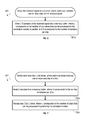
- FIG. 4 depicts functional details of correlating a received signal with a locally generated copy of the PN code using the optimized correlation method.
- FIG. 4 may be read with reference to FIG. 5 , which illustrates correlation of a received signal with a locally generated copy of the PN code.
- the received signal is divided into m slices, where each slice includes one or more chips of the received signal.
- each slice is generated when a sufficient number of samples of the received signal have been received.
- samples of the received signal corresponding to more than one slice are first stored in a storage module (e.g., a buffer, memory, solid state storage, etc.) before the m slices are generated using samples of the stored signal.
- a storage module e.g., a buffer, memory, solid state storage, etc.
- each slice is divided into L sub-slices, where each sub-slice includes one or more samples of a chip.
- a chip of the PN code, and L ⁇ 1 subsequent chips of the PN code are generated (e.g., the number of chips is equal to the number of sub-slices). In another embodiment the number of chips of the PN code generated are greater than L.
- sub-slice correlation results are generated by correlating, in parallel, samples from each of the L sub-slices with the chips of the locally generated PN code.
- slice correlation results are generated by adding the sub-slice correlation results.
- correlation results are generated by accumulating the slice correlation results.
- An example correlator module 327 configured for a chipping rate of 2.557M chips/s with a PN code of length 2047 and sampling rate of 20.46 MHz will need to process data at a rate of 654.72 e 6 MAC/s operations for a 32 chip correlation window w.
- This clock rate requires an advanced ASIC technology, and may not work on an FPGA.
- the massive processing burden can be parallelized into blocks that operate at a lower clock frequency.
- the L “lanes” together represent one time-slice of the correlator samples.
- the samples for each lane are multiplied with the corresponding chip from the PN generator and the result from each lane is added together to produce each entry of C s [n].
- the optimized correlator module design allows the correlator module to be adaptively or flexibly clocked. For instance, in order to process signals from different DSSS systems, a correlator module's frequency needs to meet a minimum frequency as dictated by received signal type and correlation window width w of a signal. This implies that optimal clock frequency for a correlator designed for multiple systems depends on the type of signal being processed at that time.
- the slice base processing in the correlator module allows clock-gating (e.g., switching OFF the clock) once a slice is processed (e.g., C s [n] is computed), and the correlator module is waiting for the next slice to be filled into a memory buffer 810 .
- the correlator module clock (not shown) can be dynamically switched to the optimal frequency for that specific signal. This fine-grained clocking flexibility helps in reducing the power consumption of the correlator module.
- FIG. 6 illustrates functional details of dividing a received signal into m slices, where each slice includes one or more chips of the received signal (i.e., step 421 of FIG. 4 ).
- L*S samples of the received signal are written into a memory buffer, where L corresponds to the number of sub-slices that can be processed by the correlator module in parallel, and S corresponds to the number of samples per chip.
- the samples are written into the memory buffer as they are received. This process continues until the memory buffer has accumulated L*S samples of the received signal, at which point downstream processing can begin.
- the L*S samples are written to the memory buffer from a signal that was previously received (e.g., the L*S samples are read from a buffer or other memory storage).
- FIG. 7 illustrates functional details of dividing each slice into L sub-slices, where each sub-slice includes one or more samples of a chip signal (i.e., step 422 of FIG. 4 ).
- S samples are read from the memory buffer, where S corresponds to the number of samples per chip.
- step 722 b step 722 a is repeated L times, where L corresponds to the number of chips that can be processed in parallel by the correlator module.
- each of the L readings of S samples sends those particular S samples to a different destination.
- there are L “multiply and accumulate” (“MAC”) modules and each group of S samples is transmitted to a different MAC or correlator module.
- MAC multiply and accumulate
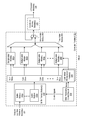
- the modules may include: buffer memory module(s) 810 that implement n memory buffers 810 a through 810 n , which are operable to perform steps 421 and 422 ; a slice processing control module 820 , which is operable to provide control signals to the buffer memory module(s) 810 when performing steps 421 and 422 ; one or more look-ahead PN generator module(s) (“PN generators”) 830 , which are operable to perform step 423 ; L multiplication modules 840 a through 840 n , and a tree adder module 850 , which are operable to perform steps 424 and 425 ; and an accumulator module 860 , which is operable to perform step 426 .
- buffer memory module(s) 810 that implement n memory buffers 810 a through 810 n , which are operable to perform steps 421 and 422 ;
- a slice processing control module 820 which is operable to provide control signals to the buffer memory module(s) 810 when performing steps 421 and
- the buffer memory module(s) 810 are coupled to the frontend module(s) 321 , the slice processing control module 820 and the multiplication modules 840 ; the slice processing control module 820 is coupled to the look-ahead PN generator module 830 ; the look-ahead PN generator module 830 is coupled to the multiplication modules 840 ; the multiplication modules 840 are coupled to the tree adder module 850 ; the tree adder module 850 is coupled to the accumulator module 860 , which is coupled to the correlation memory module(s) 328 ; and the correlation memory module(s) 328 are coupled to the processor module(s) 329 .
- samples from the frontend module(s) 321 are written into an available memory buffer 810 (e.g., memory buffer 810 a ).
- the buffer memory module(s) 810 implement a circular buffer made up of n memory buffers.
- Control signals are transmitted from the slice processing control module 820 to the buffer memory module(s) 810 to control the writing and reading (e.g., addressing) of the memory buffers modules 810 .
- L*S incoming samples are written into the available memory buffer 810 .
- the L*S samples previously written to memory buffer 810 n are read.
- Each of the L groups of S samples read are transmitted to a different parallel multiplication module 840 of the L multiplication modules 840 a through 840 l.
- the look-ahead PN generator module(s) 830 also receive control signals (e.g., a strobe) from the slice processing control module 820 .
- the control signals are used by the PN module 830 to control the advancement of the PN module's state.
- PN chips from the PN module 830 are transmitted to the multiplication modules 840 a - l . Each PN chip is multiplied with a sample of the S samples corresponding to a particular multiplication module 840 .
- Each result from each of the multiplication modules 840 a - l is transmitted to the tree adder module 850 .
- the tree adder module 850 adds the multiplication results transmitted from each of the multiplication modules 840 a - l for each of the S samples corresponding to that multiplication module 840 , producing a total sum for the L multiplication modules 840 a - l . That is, the tree adder is used for both steps 424 and 425 of FIG. 4 to generate a slice correlation result.
- the slice correlation result from the tree adder module 850 is transmitted to the accumulator module 860 .
- the accumulator module accumulates the tree adder's result with the previous slice's sum to generate a correlation result.
- the correlation result is considered to be complete when all of the slices of a transmitted signal have been accumulated.
- the correlation result is then transmitted to the processor module(s) 329 .
- any of the frontend module(s), correlator module(s), correlation memory module(s), and/or processor module(s) may be implemented using an FPGA, an ASIC, one or more digital signal processors, or other suitable module.
- the correlator module 327 is implemented using an FPGA.
- the correlator module 327 is implemented using an ASIC.
- the correlator module is implemented using one or more digital signal processors.
- Other suitable modules are contemplated as would be understood by one of ordinary skill in the art.
- FIG. 9 illustrates one embodiment of the buffer memory module(s) 810 used for improving correlation.
- L*S samples from the frontend module(s) 321 are written into the memory buffer 810 a .
- the memory buffer 810 a implements L columns, where each column contains S samples.
- each column corresponds to a sub-slice of the slice of L*S samples.
- each column e.g., sub-slice
- each multiplication module 840 is “responsible” for all S samples of a sub-slice.
- the buffer memory module(s) 810 are implemented in an FPGA or ASIC using a standard memory systems (e.g., RAM) commonly available in FPGA/ASIC systems, as opposed to using D-Flip-Flop/register-array elements.
- the memory meets at least the following criteria: dimensions of at least 2*S*L*W, where W is the bit-width of each of the S samples; L column write-enables; simple dual port (e.g., one write-port, one read-port); and independent write and read clocks.
- the buffer memory module(s) 810 are separately clocked at read and write ports, which offers flexibility to use various combinations of clock rates for the correlator module(s) 327 . This is advantageous as it makes the interface to the processor modules(s) 329 independent of the frontend clock domain. Indeed, one embodiment of a system offers flexibility to use various combinations of clock rates for the correlator module, un-coupled from a frontend module.
- PN code generators such as linear-feedback shift registers (LFSR's) are well known in the art.
- LFSR's linear-feedback shift registers
- a modified PN code generator topology may be used to correlate samples of a received signal in parallel, where the received signal has been decomposed into slices and sub-slices.
- the modifications enable the modified PN code generator to produce L chips of a PN code in parallel across a correlation window of width, w, and then adjust the state of the PN generator to process the next slice of received data.
- FIG. 10 illustrates functional details of generating a chip of a PN code, and L ⁇ 1 subsequent chips (or more) of the PN code.
- a local PN generator is selected. That is, a particular look-ahead PN generator module 830 is chosen for use (e.g., by a processor module).
- the correlator module(s) 327 has more than one PN generator module 830 , where each of the PN generator modules 830 is configured to generate one or more particular PN codes corresponding to particular DSSS systems.
- a PN generator 830 that supports GPS L1 C/A, GLONASS L1 C/A or Beidou L1 B1I signal specifications would be selected as appropriate. Such signal specifications are illustrated in the table of FIG. 13 .
- initialization values associated with the selected PN generator are identified (e.g., from a lookup table by a processor module).
- a PRN seed represents the initial state of the PN generator. Use of these initialization values is discussed later with reference to FIG. 12 .
- Step 1023 b may have occurred as part of step 1023 a .
- a particular PN generator 830 may be pre-configured to generate a PN code associated with a particular DSSS system (e.g., GPS).
- the selected PN generator 830 is configured using the initialization values.
- a ‘current slice start’ state, A, of the PN generator is identified. This state corresponds to state of the PN generator 830 before its state is advanced w-1 times, where w specifies the width of a correlation window.
- a next-value is determined using a next-value function of a next-value module.
- the state of the PN generator 830 is advanced using the next-value of the PN generator (e.g., by loading the next-value(s) into a register of the PN generator).
- a chip of the PN code and L ⁇ 1 subsequent chips of the PN code are identified by reading L chips from the register.
- steps 1030 through 1040 are repeated w-1 times, where w is the width of the correlation window.
- the state of the PN generator, A+L (the state A, advanced by L chips), is determined using one or more next-value functions.
- the PN generator is set to the state of state of A+L.
- Step 1023 i is performed because, at step 1023 h , the PN generator 830 was advanced w-1 times in order to correlate each of the samples of the current slice with chips of the PN code spanning the entire correlation window w.
- the next samples need to be correlated with chips of the PN code only advanced by L chips relative to what the state of the PN code was at the beginning of the previous slice. Therefore, it is necessary to return the PN generator to the state that is only advanced by L chips relative to the state of the PN generator at the beginning of the previous slice. This is illustrated and discussed later with reference to FIG. 11 .
- FIG. 11 illustrates a series of chips of a PN code as the state of a PN generator is advanced in time.
- Each row of the series 1105 through 1110 and the series 1115 through 1120 shows the PN code generated at a particular state of the PN generator.
- the state of the PN generator is advanced between each row.
- Samples of the received signal shown correspond to two slices, Slice 0 and Slice 1 .
- Samples S 0 through S 15 correspond to the samples of Slice 0 and samples S 16 through S 31 correspond to samples of Slice 1 .
- a series of L chips of a PN code are generated across a correlation window w. That is, the state of the PN generator is advanced w-1 times from the initial state. Each time the PN generator is advanced, it generates L chips of the PN sequence in parallel (e.g., PN ⁇ 1 , PN 0 , PN 1 and PN 2 ). As the state of the PN generator is advanced, the chips of the PN sequence “slide” relative to samples of the received signal. For example, the chips of the PN sequence shown in row 1110 have been advanced five times relative to the chips shown in row 1105 .
- a chip of the PN code is correlated with a different sample of the received signal. For example, at the time corresponding to row 1105 , chip P 2 will be correlated with sample S 15 . After the state of the PN generator has been advanced 5 times, as shown at row 1110 , chip P 2 will be correlated with sample S 10 .
- FIG. 12 illustrates one embodiment of the look-ahead PN generator module 830 used for improving correlation.
- the look-ahead PN generator module (“PN Generator”) 830 includes various modules that are each operable to carry out different steps of FIG. 10 .
- the modules may include: an initialization register 1230 a ; an advance L hold register 1230 b ; an advancement decision module 1230 c ; a register 1230 d ; a polynomial initialization register 1230 e ; and next-value function modules 1230 f through 1230 n .
- the next-value function modules are cascaded L times.
- the initialization register 1230 a is coupled to the register 1230 d ; the polynomial initialization register 1230 e is coupled to the next-value functions 1230 f through 1230 n ; at least one of the next-value function modules 1230 f and 1230 n is coupled to the hold register 1230 b ; at least one of the next-value function modules 1230 f and 1230 n is coupled to the advancement decision module 1230 c ; the hold register 1230 b is coupled to the advancement decision module 1230 c ; and the advancement decision module 1230 c is coupled to the register 1230 d.
- the initialization register 1230 a contains the PN code seed which is loaded into the register 1230 d to set the initial state of the PN generator.
- the polynomial initialization register 1230 e contains initial values that will be used by the cascaded next-value function modules 1230 f through 1230 n with an indication of which taps should be used to express a particular polynomial.
- the next-value function module 1230 f is used to determine a value produced using one or more bits of the register 1230 d .
- the next-value function module 1230 f performs a logical XOR operation on two or more bits of the register 1230 d to generate the next-value.
- the next-value function module 1230 f performs a different operation using bits of the register 1230 d to generate the next-value.
- next-value function module 1230 f and the advancement decision module 1230 c are operable to perform step 1023 f of FIG. 10 .
- the next-value is passed from the next-value function module 1230 f through the advancement decision module 1230 c and loaded into the register 1230 d.
- the register 1230 d is operable to perform 1023 g of FIG. 10 , whereby a chip of the PN code and L ⁇ 1 subsequent chips of the PN code are identified by reading L chips from the register 1230 d .
- the next-value is loaded into the register 1230 d and the L chips of the PN code are read from the MSB portion of the register 1230 d.
- the state of the PN generator, C+L (the state C, advanced by L chips), is determined using one or more of the L cascaded next-value functions 1230 f through 1230 n.
- the L cascaded next-value registers 1230 f through 1230 n are used to determine the state of the PN generator advanced by L chips from the state of the PN generator at the beginning of the slice that is currently being processed by the correlator module(s) 327 . This state is denoted as “C+L”. Upon determining L next-values (chips) of state C+L, these values are loaded into the advance L hold register 1230 b and stored until processing of the current slice is complete.
- the advancement decision module 1230 c loads the next-value produced by the next-value function module 1230 f into the register 1230 d .
- the L next-value chips stored in the advance L hold register 1230 b are loaded into the register 1230 b via the advancement decision module 1230 c.
- FIG. 13 illustrates example signal specifications used in a variety of Direct-Sequence Spread Spectrum (DSSS) based positioning systems.
- the table shown in FIG. 13 provides example signal specifications of satellite-based positioning systems such as GPS, GLONASS and Beidou as well as signal specifications of a terrestrial-based positioning system, Metropolitan Beacon System (MBS) as implemented by NextNav, LLC.
- satellite-based positioning systems such as GPS, GLONASS and Beidou
- MBS Metropolitan Beacon System
- machine-readable media includes all forms of statutory machine-readable media (e.g. statutory non-volatile or volatile storage media, statutory removable or non-removable media, statutory integrated circuit media, statutory magnetic storage media, statutory optical storage media, or any other statutory storage media). As used herein, machine-readable media does not include non-statutory media.
- machines may include one or more computing device(s), processor(s), controller(s), integrated circuit(s), chip(s), system(s) on a chip, server(s), programmable logic device(s), other circuitry, and/or other suitable means described herein or otherwise known in the art.
- Method steps described herein may be order independent, and can therefore be performed in an order different from that described. It is also noted that different method steps described herein can be combined to form any number of methods, as would be understood by one of skill in the art. It is further noted that any two or more steps described herein may be performed at the same time. Any method step or feature disclosed herein may be expressly restricted from a claim for various reasons like achieving reduced manufacturing costs, lower power consumption, and increased processing efficiency. Method steps performed by a transmitter or a receiver can be performed by a server, or vice versa.
- Systems comprising one or more modules that perform, are operable to perform, or adapted to perform different method steps/stages disclosed herein are also contemplated, where the modules are implemented using one or more machines listed herein or other suitable hardware.
- two things e.g., modules or other features
- those two things may be directly connected together (e.g., shown by a line connecting the two things in the drawings), or separated by one or more intervening things. Where no lines and intervening things connect two particular things, coupling of those things is contemplated unless otherwise stated.
- information sent from the output is received by the input even if the data passes through one or more intermediate things.
- All information disclosed herein may be transmitted over any communication pathway using any protocol.
- Data, instructions, commands, information, signals, bits, symbols, and chips and the like may be represented by voltages, currents, electromagnetic waves, magnetic fields or particles, or optical fields or particles.
- the words comprise, comprising, include, including and the like are to be construed in an inclusive sense (i.e., not limited to) as opposed to an exclusive sense (i.e., consisting only of). Words using the singular or plural number also include the plural or singular number, respectively.
- the word or and the word and, as used in the Detailed Description cover any of the items and all of the items in a list.
- the words some, any and at least one refer to one or more.
- the term may is used herein to indicate an example, not a requirement—e.g., a thing that may perform an operation or may have a characteristic need not perform that operation or have that characteristic in each embodiment, but that thing performs that operation or has that characteristic in at least one embodiment.
- transmitters described herein may include: antenna module(s) for exchanging signals with other systems; RF front end module(s) with circuitry components that are known or disclosed herein); processing module(s) for performing signal processing (e.g., generating signals for transmission at a selected time, using a selected frequency, using a selected code, and/or using a selected phase), methods described herein, or other processing; memory module(s) for providing storage and retrieval of data and/or instructions relating to methods of operation described herein that may be executed by the processing module(s); sensors module(s) for measuring conditions at or near the transmitter (e.g., pressure, temperature, humidity, wind, or other); and/or interface module(s) for exchanging information with other systems via other links other than a radio link.
- Signals transmitted by a transmitter may carry different information that, once determined by a receiver or a server, may identify the following: the transmitter; the transmitter's location (LLA); pressure, temperature, humidity, and/or other conditions at or near the transmitter.
- a receiver may be in the form of a computing device (e.g., a mobile phone, tablet, laptop, digital camera, tracking tag), and may include any of: antenna module(s) for exchanging signals with other systems; RF front end module(s) with circuitry components that are known or disclosed herein; processing module(s) for signal processing of received signals to determine position information (e.g., times of arrival or travel time of received signals, atmospheric information from transmitters, and/or location or other information associated with each transmitter), for using the position information to compute an estimated position of the receiver, for performing methods described herein, and/or for performing other processing; memory module(s) for providing storage and retrieval of data and/or instructions relating to methods of operation described herein that may be executed by the processing module(s) or other module(s); sensor module(s) for measuring environmental conditions at or near the receiver (e.g., pressure, temperature, humidity, wind, other), which may be compared to the same environmental conditions at or near transmitters to determine the altitude of the receiver; other sensor module(s) for
- positioning system may refer to satellite systems (e.g., Global Navigation Satellite Systems (GNSS) like GPS, GLONASS, Galileo, and Compass/Beidou), terrestrial systems, and hybrid satellite/terrestrial systems.
- GNSS Global Navigation Satellite Systems
Landscapes
- Engineering & Computer Science (AREA)
- Physics & Mathematics (AREA)
- General Physics & Mathematics (AREA)
- Mathematical Analysis (AREA)
- Computational Mathematics (AREA)
- Mathematical Optimization (AREA)
- Pure & Applied Mathematics (AREA)
- Theoretical Computer Science (AREA)
- Signal Processing (AREA)
- Computer Networks & Wireless Communication (AREA)
- Computing Systems (AREA)
- General Engineering & Computer Science (AREA)
- Synchronisation In Digital Transmission Systems (AREA)
Abstract
Description
where C is the correlation function, x is the received signal sampled at one sample per chip, c is the locally generated PN code, n is the current position in the correlation window, P is the length of the PN code and w is the width of the correlation window, and % P describes the wrap-around of the PN code sequence after the last value.
where P′ is the number of samples in each slice, and % P describes the wrap-around of the PN code sequence after the last value.
C[n]=Σ i=0 k−1 Cs i [n] (Equation 3)
Claims (10)
Priority Applications (1)
| Application Number | Priority Date | Filing Date | Title |
|---|---|---|---|
| US15/491,653 US10175945B2 (en) | 2016-06-17 | 2017-04-19 | Methods and systems for improving correlation |
Applications Claiming Priority (2)
| Application Number | Priority Date | Filing Date | Title |
|---|---|---|---|
| US201662351825P | 2016-06-17 | 2016-06-17 | |
| US15/491,653 US10175945B2 (en) | 2016-06-17 | 2017-04-19 | Methods and systems for improving correlation |
Publications (2)
| Publication Number | Publication Date |
|---|---|
| US20170366219A1 US20170366219A1 (en) | 2017-12-21 |
| US10175945B2 true US10175945B2 (en) | 2019-01-08 |
Family
ID=60661458
Family Applications (1)
| Application Number | Title | Priority Date | Filing Date |
|---|---|---|---|
| US15/491,653 Active US10175945B2 (en) | 2016-06-17 | 2017-04-19 | Methods and systems for improving correlation |
Country Status (1)
| Country | Link |
|---|---|
| US (1) | US10175945B2 (en) |
Cited By (3)
| Publication number | Priority date | Publication date | Assignee | Title |
|---|---|---|---|---|
| US10775510B2 (en) | 2016-06-06 | 2020-09-15 | Brian G. Agee | Blind despreading of civil GNSS signals for resilient PNT applications |
| US12228656B2 (en) | 2016-06-06 | 2025-02-18 | Brian G. Agee | Resilient despreading of terrestrial navigation signals |
| US12386015B2 (en) | 2020-02-03 | 2025-08-12 | Brian G. Agee | Resilient distributed positioning networks |
Families Citing this family (3)
| Publication number | Priority date | Publication date | Assignee | Title |
|---|---|---|---|---|
| US10742258B1 (en) * | 2018-09-26 | 2020-08-11 | Novatel Inc. | System and method for demodulating code shift keying data utilizing correlations with combinational PRN codes generated for different bit positions |
| US10742257B1 (en) * | 2018-09-26 | 2020-08-11 | Novatel Inc. | System and method for demodulating code shift keying data from a satellite signal utilizing a binary search |
| CN110493604A (en) * | 2019-08-28 | 2019-11-22 | 成都索贝数码科技股份有限公司 | A method of 8K HEVC real-time coding is realized based on GPU cluster |
Citations (7)
| Publication number | Priority date | Publication date | Assignee | Title |
|---|---|---|---|---|
| US20030112856A1 (en) * | 2001-12-14 | 2003-06-19 | Raghu Challa | Acquisition of a gated pilot signal with coherent and noncoherent integration |
| US20050254560A1 (en) * | 2004-05-17 | 2005-11-17 | Huang Yi P | Apparatus and method for acquiring spread-spectrum signals |
| US20100220706A1 (en) * | 2001-03-22 | 2010-09-02 | Ghobad Heidari | Apparatus, Module, And Method For Implementing Communications Functions |
| US20110007783A1 (en) * | 2008-02-28 | 2011-01-13 | Magellan Systems Japan, Inc. | Method and apparatus for acquisition, tracking, and sub-microsecond time transfer using weak gps/gnss signals |
| US20110122926A1 (en) * | 2008-08-22 | 2011-05-26 | Seung Il Myong | Apparatus and method for generating pseudo noise code |
| US20130136155A1 (en) * | 2007-12-14 | 2013-05-30 | Magellan Systems Japan, Inc. | Process for sub-microsecond time transfer using weak gps/gnss signals |
| US20140254636A1 (en) * | 2013-03-11 | 2014-09-11 | Freescale Semiconductor, Inc. | System and method for demodulating an incoming signal |
-
2017
- 2017-04-19 US US15/491,653 patent/US10175945B2/en active Active
Patent Citations (7)
| Publication number | Priority date | Publication date | Assignee | Title |
|---|---|---|---|---|
| US20100220706A1 (en) * | 2001-03-22 | 2010-09-02 | Ghobad Heidari | Apparatus, Module, And Method For Implementing Communications Functions |
| US20030112856A1 (en) * | 2001-12-14 | 2003-06-19 | Raghu Challa | Acquisition of a gated pilot signal with coherent and noncoherent integration |
| US20050254560A1 (en) * | 2004-05-17 | 2005-11-17 | Huang Yi P | Apparatus and method for acquiring spread-spectrum signals |
| US20130136155A1 (en) * | 2007-12-14 | 2013-05-30 | Magellan Systems Japan, Inc. | Process for sub-microsecond time transfer using weak gps/gnss signals |
| US20110007783A1 (en) * | 2008-02-28 | 2011-01-13 | Magellan Systems Japan, Inc. | Method and apparatus for acquisition, tracking, and sub-microsecond time transfer using weak gps/gnss signals |
| US20110122926A1 (en) * | 2008-08-22 | 2011-05-26 | Seung Il Myong | Apparatus and method for generating pseudo noise code |
| US20140254636A1 (en) * | 2013-03-11 | 2014-09-11 | Freescale Semiconductor, Inc. | System and method for demodulating an incoming signal |
Cited By (5)
| Publication number | Priority date | Publication date | Assignee | Title |
|---|---|---|---|---|
| US10775510B2 (en) | 2016-06-06 | 2020-09-15 | Brian G. Agee | Blind despreading of civil GNSS signals for resilient PNT applications |
| US10983221B2 (en) | 2016-06-06 | 2021-04-20 | Brian G. Agee | Adaptive despreading of civil beacons and GNSS signals using a channelized vector processing architecture |
| US10996339B2 (en) | 2016-06-06 | 2021-05-04 | Brian G. Agee | Adaptive despreading and geolocation 1 of civil beacons and GNSS signals |
| US12228656B2 (en) | 2016-06-06 | 2025-02-18 | Brian G. Agee | Resilient despreading of terrestrial navigation signals |
| US12386015B2 (en) | 2020-02-03 | 2025-08-12 | Brian G. Agee | Resilient distributed positioning networks |
Also Published As
| Publication number | Publication date |
|---|---|
| US20170366219A1 (en) | 2017-12-21 |
Similar Documents
| Publication | Publication Date | Title |
|---|---|---|
| US10175945B2 (en) | Methods and systems for improving correlation | |
| US7898475B2 (en) | GNSS receiver with reduced storage requirements | |
| JP6246966B2 (en) | GNSS signal processor | |
| US7471717B2 (en) | Apparatus and method for acquiring spread-spectrum signals | |
| US9000980B2 (en) | GNSS receiver correlating doppler derotation samples with code phases | |
| EP3094989B1 (en) | A processor for a radio receiver | |
| JP2010526997A5 (en) | ||
| US9612339B2 (en) | Detecting satellite signals by storing signal sets spanning code period | |
| KR100995542B1 (en) | Perform correlation at reception of spread spectrum signal | |
| US7526014B2 (en) | Correlator for spread spectrum receiver | |
| US10444369B2 (en) | Systems and methods for generating signals from terrestrial transmitters, and for processing the signals using GNSS receiver hardware | |
| US11624841B2 (en) | Systems and methods for GNSS receivers | |
| US7477186B2 (en) | Memory systems with column read to an arithmetic operation circuit, pattern detector circuits and methods and computer program products for the same | |
| US8520719B2 (en) | Multiple-mode correlator | |
| CN104049263B (en) | The base band statistical multiplex method of reseptance of multimodal satellite navigation signal | |
| US20160161613A1 (en) | System and method for using gnss tracking correlators for terrestrial beacons | |
| US7590828B2 (en) | Processing a data word in a plurality of processing cycles | |
| JP2005333456A (en) | Spread spectrum signal receiver | |
| US20080151970A1 (en) | Fractional chip correlation device and method for operating fractional chip correlation in spread spectrum receiver | |
| WO2005062479A1 (en) | Tracking a code modulated signal | |
| CN120225915A (en) | Method and apparatus for performing a small batch discrete fourier transform to track satellite signals | |
| WO2024154020A1 (en) | Methods and apparatuses for spread-spectrum data transmission and reception | |
| JPH0697775A (en) | Digital matched filter | |
| JP2020068505A (en) | Code generation device and spread spectrum signal reception system |
Legal Events
| Date | Code | Title | Description |
|---|---|---|---|
| AS | Assignment |
Owner name: NEXTNAV, LLC, CALIFORNIA Free format text: ASSIGNMENT OF ASSIGNORS INTEREST;ASSIGNORS:MEIYAPPAN, SUBRAMANIAN S;KALKUNTE, VIKRAM V;REEL/FRAME:042067/0022 Effective date: 20170331 |
|
| STCF | Information on status: patent grant |
Free format text: PATENTED CASE |
|
| AS | Assignment |
Owner name: FORTRESS CREDIT CORP., AS AGENT, NEW YORK Free format text: ASSIGNMENT FOR SECURITY -- PATENTS;ASSIGNORS:NEXTNAV, LLC;PROGENY LMS, LLC;REEL/FRAME:051433/0692 Effective date: 20191227 |
|
| AS | Assignment |
Owner name: NEXTNAV, LLC, VIRGINIA Free format text: RELEASE BY SECURED PARTY;ASSIGNOR:FORTRESS CREDIT CORP.;REEL/FRAME:057973/0636 Effective date: 20211028 Owner name: NEXTNAV, LLC, VIRGINIA Free format text: RELEASE OF SECURITY INTEREST;ASSIGNOR:FORTRESS CREDIT CORP.;REEL/FRAME:057973/0636 Effective date: 20211028 |
|
| MAFP | Maintenance fee payment |
Free format text: PAYMENT OF MAINTENANCE FEE, 4TH YEAR, LARGE ENTITY (ORIGINAL EVENT CODE: M1551); ENTITY STATUS OF PATENT OWNER: LARGE ENTITY Year of fee payment: 4 |
|
| AS | Assignment |
Owner name: GLAS TRUST COMPANY LLC, NEW JERSEY Free format text: SECURITY INTEREST;ASSIGNORS:NEXTNAV INC.;NEXTNAV HOLDINGS, LLC;NEXTNAV INTERMEDIATE HOLDCO, LLC;AND OTHERS;REEL/FRAME:070691/0909 Effective date: 20250327 |