US1017450A - Blowpipe-carrier. - Google Patents
Blowpipe-carrier. Download PDFInfo
- Publication number
- US1017450A US1017450A US55779210A US1910557792A US1017450A US 1017450 A US1017450 A US 1017450A US 55779210 A US55779210 A US 55779210A US 1910557792 A US1910557792 A US 1910557792A US 1017450 A US1017450 A US 1017450A
- Authority
- US
- United States
- Prior art keywords
- pipe
- blow
- carrier
- hook
- blowpipe
- Prior art date
- Legal status (The legal status is an assumption and is not a legal conclusion. Google has not performed a legal analysis and makes no representation as to the accuracy of the status listed.)
- Expired - Lifetime
Links
- 239000011521 glass Substances 0.000 description 7
- 238000007664 blowing Methods 0.000 description 1
- 235000021438 curry Nutrition 0.000 description 1
- 238000010438 heat treatment Methods 0.000 description 1
- 230000037431 insertion Effects 0.000 description 1
- 238000003780 insertion Methods 0.000 description 1
- 239000002184 metal Substances 0.000 description 1
- 229920000136 polysorbate Polymers 0.000 description 1
- 239000000725 suspension Substances 0.000 description 1
Images
Classifications
-
- B—PERFORMING OPERATIONS; TRANSPORTING
- B65—CONVEYING; PACKING; STORING; HANDLING THIN OR FILAMENTARY MATERIAL
- B65G—TRANSPORT OR STORAGE DEVICES, e.g. CONVEYORS FOR LOADING OR TIPPING, SHOP CONVEYOR SYSTEMS OR PNEUMATIC TUBE CONVEYORS
- B65G7/00—Devices for assisting manual moving or tilting heavy loads
- B65G7/12—Load carriers, e.g. hooks, slings, harness, gloves, modified for load carrying
Definitions
- My invention relates to the art of automatically blowing glass cylinders by machinery, and especially to the blow-pipes used in such apparatus, its primary object being to provide a convenient and safe means of handling the hot blow-pipe.
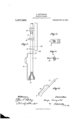
- Figure 1 is a side elevation, with parts in section, showing a blow-pipe in place in the suspension device of the machine and the carrier thereon ready to be removed.
- Figs. 2 and 3 are plans of the blow-pipe fork and the hook engaging the blow-pipe, and Fig. 4 illustrates the position in which the blowpipe is to be carried.
- blow-pipes are highly heated on the bait end, so that upon insertion in the machine and being dropped into the glass bath, the metal of the pipe will adhere to the glass so the latter may be drawn up into the cylinder. It has been customary to carry these pipes from the heating furnace to the machine, and insert them therein by hand. This is a diificult and risky operation, because the operator must use gloves which often become slippery, and any contact with the blow-pipe bait would'cause a serious burn.
- the blow-pipe is inserted under the air feed pipe in an inclined position and placed between the fingers of a fork, after which it is turned to a vertical position in order to efi'ect a joint with the feed pipe and at the same time fasten the blow-pipe in the machine.
- the pipes being heavy and being thus required to be angularly moved, are generally carried near the workmans shoulder. The reflected heat is inconvenient and often painful.
- the present invention obviates the necessity of using gloves, or of approaching the hands close to the hot pipe, or lifting the pipe to the shoulder, or of turning it several times in angular direction.
- a carrier for glass working blow-pipes comprising a hook adapted to be inserted in an axial hole in the heavy end of the pipe and another hook to embrace the stem, whereby the inclined position of the pipe retains the hold and enables the pipe to be moved without touching with the hands.
- a carrier for glass working blow-pipes comprising a member having an upturned hook at one end to fit within the lower portion of a blow-pipe, a laterally turned hook at its other end to embrace the stem of the blow-pipe, and a handheld or grip intermediate of the hooks; substantially as described.
- a carrier for glass working blow-pipes comprising a rod having a grasping portion for the hand, a laterally bent hook to engage the stem of the pipe, and a longitudinally bent hook adapted to enter in a generally axial direction the hollow end of the pipe, substantially as described.
- a carrier for glass working blow-pipes comprising a member having an upturned hook at one end to fit within the axial opening in thelower portion of a blow-pipe, a laterally turned hook at its other end to embrace the stem of the blow-pipe, and a hand- In testimony whereof I have hereunto hold or grip intermediate of the hooks, the signed my name in the presence of the two portion of the member between the hooks subscribed witnesseses.
Landscapes
- Manipulator (AREA)
Description
Gr. NEVERGOLD.
' BLOWPIPE CARRIER.
APPLICATION FILED APR.-26,1910.
1,017,450. Patented Feb. 13, 1912.
7\\ZE FgzZ.
COLUMBIA PLANOGIAPH $0.. WASHINGTON, n. c.
UNITED STATES PATENT OFFICE. i
GEORGE NEVERGOLD, OF JEANNETTE, PENNSYLVANIA, ASSIGNOR TO WINDOW GLASS MACHINE COMPANY, OF PITTSBURGH, PENNSYLVANIA, A CORPORATION OF NEW JERSEY.
BLOWPIPE-CARRIER.
Specification of Letters Patent.
Patented Feb. 13, 1912.
Application filed April 26, 1910. Serial No. 557,792.
To all whom it may concern:
Be it known that- I, GEORGE ITEVERGOLD, a citizen of the United States, residing at Jeannette, in the State of Pennsylvania, have invented a certain new and useful Blowpipe-Carrier, of which the following is a specification.
My invention relates to the art of automatically blowing glass cylinders by machinery, and especially to the blow-pipes used in such apparatus, its primary object being to provide a convenient and safe means of handling the hot blow-pipe.
I have illustrated the invention in a simple form in the accompanying drawing, in which Figure 1 is a side elevation, with parts in section, showing a blow-pipe in place in the suspension device of the machine and the carrier thereon ready to be removed. Figs. 2 and 3 are plans of the blow-pipe fork and the hook engaging the blow-pipe, and Fig. 4 illustrates the position in which the blowpipe is to be carried.
It will be understood that the blow-pipes are highly heated on the bait end, so that upon insertion in the machine and being dropped into the glass bath, the metal of the pipe will adhere to the glass so the latter may be drawn up into the cylinder. It has been customary to carry these pipes from the heating furnace to the machine, and insert them therein by hand. This is a diificult and risky operation, because the operator must use gloves which often become slippery, and any contact with the blow-pipe bait would'cause a serious burn. In the machines in common use, the blow-pipe is inserted under the air feed pipe in an inclined position and placed between the fingers of a fork, after which it is turned to a vertical position in order to efi'ect a joint with the feed pipe and at the same time fasten the blow-pipe in the machine. The pipes being heavy and being thus required to be angularly moved, are generally carried near the workmans shoulder. The reflected heat is inconvenient and often painful.
The present invention obviates the necessity of using gloves, or of approaching the hands close to the hot pipe, or lifting the pipe to the shoulder, or of turning it several times in angular direction.
In the drawing it will be observed that the blow-pipe 5, with the bait at the lower a hook 10 substantially of the form shown,
having an upturned part 11 to insert into the bait end of the pipe, and a lateral hook 12 to surround the stem of the pipe. The end 11 being inserted in the furnace where the blow-pipe is heated, the blow-pipe is lifted up and carried in the position shown in Fig. 4, by one hand, and the operator approaching the machine has the blow-pipe already in position to insert in the machine by a simple forward thrust and then dropping the heavy end downward, after which the carrier 10 is slid downward to release the hook 11, whereupon the hook 12 is also released. By this means the pipe is carried to place and put into position with a simple and single motion and without touching with the hands. The advantages will occur to those familiar with the practice of this art.
Having thus described my invention, what I claim is:
1. A carrier for glass working blow-pipes, comprising a hook adapted to be inserted in an axial hole in the heavy end of the pipe and another hook to embrace the stem, whereby the inclined position of the pipe retains the hold and enables the pipe to be moved without touching with the hands.
2. A carrier for glass working blow-pipes, comprising a member having an upturned hook at one end to fit within the lower portion of a blow-pipe, a laterally turned hook at its other end to embrace the stem of the blow-pipe, and a handheld or grip intermediate of the hooks; substantially as described.
3. A carrier for glass working blow-pipes, comprising a rod having a grasping portion for the hand, a laterally bent hook to engage the stem of the pipe, and a longitudinally bent hook adapted to enter in a generally axial direction the hollow end of the pipe, substantially as described.
4. A carrier for glass working blow-pipes, comprising a member having an upturned hook at one end to fit within the axial opening in thelower portion of a blow-pipe, a laterally turned hook at its other end to embrace the stem of the blow-pipe, and a hand- In testimony whereof I have hereunto hold or grip intermediate of the hooks, the signed my name in the presence of the two portion of the member between the hooks subscribed Witnesses.
being of a length less than the distance be- GEO. NEVERGOLD. 5 tween the lower end of the blow-pipe and WVitnesses:
the point Where the latter engages its sup- E. C. CURRY,
port; substantially as described. G. P. VEEKS.
Copies of this patent may be obtained for five cents each, by addressing the Commissioner of Patents, Washington, D. O.
Priority Applications (1)
| Application Number | Priority Date | Filing Date | Title |
|---|---|---|---|
| US55779210A US1017450A (en) | 1910-04-26 | 1910-04-26 | Blowpipe-carrier. |
Applications Claiming Priority (1)
| Application Number | Priority Date | Filing Date | Title |
|---|---|---|---|
| US55779210A US1017450A (en) | 1910-04-26 | 1910-04-26 | Blowpipe-carrier. |
Publications (1)
| Publication Number | Publication Date |
|---|---|
| US1017450A true US1017450A (en) | 1912-02-13 |
Family
ID=3085752
Family Applications (1)
| Application Number | Title | Priority Date | Filing Date |
|---|---|---|---|
| US55779210A Expired - Lifetime US1017450A (en) | 1910-04-26 | 1910-04-26 | Blowpipe-carrier. |
Country Status (1)
| Country | Link |
|---|---|
| US (1) | US1017450A (en) |
Cited By (1)
| Publication number | Priority date | Publication date | Assignee | Title |
|---|---|---|---|---|
| CN111517062A (en) * | 2020-04-28 | 2020-08-11 | 马鞍山市神飞机械配件制造有限公司 | Straight thread sleeve clamping device |
-
1910
- 1910-04-26 US US55779210A patent/US1017450A/en not_active Expired - Lifetime
Cited By (1)
| Publication number | Priority date | Publication date | Assignee | Title |
|---|---|---|---|---|
| CN111517062A (en) * | 2020-04-28 | 2020-08-11 | 马鞍山市神飞机械配件制造有限公司 | Straight thread sleeve clamping device |
Similar Documents
| Publication | Publication Date | Title |
|---|---|---|
| US1017450A (en) | Blowpipe-carrier. | |
| US2749173A (en) | Gripping apparatus for handling elongated objects | |
| CN107718034A (en) | A kind of anti-skidding conveying robot | |
| US1422538A (en) | Tool | |
| US2367889A (en) | Carrying tongs | |
| US776591A (en) | Clinker-catcher. | |
| US705277A (en) | Brick-carrier. | |
| CN205294603U (en) | Adjust the hook | |
| US2080526A (en) | Device for holding drill bits | |
| CN206519859U (en) | Clamp | |
| CN205254825U (en) | Crucible tong | |
| US1364589A (en) | Pipe-lifter | |
| US958594A (en) | Tongs. | |
| US1350331A (en) | Shelf-reacher | |
| CN206033020U (en) | Rapid hoisting tool | |
| US1843245A (en) | Acetylene and oxygen tank carrier | |
| CN211812989U (en) | Hoisting device | |
| US833408A (en) | Flexible pipe connection. | |
| CN205990185U (en) | A kind of overhead traveling crane eave tile anti-drop device | |
| US527648A (en) | Tongs for handling metal | |
| US240965A (en) | Geoege p | |
| US1021469A (en) | Machinery for engaging and carrying loads. | |
| US346136A (en) | Crucible-tongs | |
| US2509484A (en) | Locomotive tire tongs | |
| US1122046A (en) | Extractor for core-barrels. |