US10171019B1 - Controller for power converter - Google Patents
Controller for power converter Download PDFInfo
- Publication number
- US10171019B1 US10171019B1 US15/636,916 US201715636916A US10171019B1 US 10171019 B1 US10171019 B1 US 10171019B1 US 201715636916 A US201715636916 A US 201715636916A US 10171019 B1 US10171019 B1 US 10171019B1
- Authority
- US
- United States
- Prior art keywords
- motor
- flux
- value
- command value
- power converter
- Prior art date
- Legal status (The legal status is an assumption and is not a legal conclusion. Google has not performed a legal analysis and makes no representation as to the accuracy of the status listed.)
- Active
Links
Images




Classifications
-
- H—ELECTRICITY
- H02—GENERATION; CONVERSION OR DISTRIBUTION OF ELECTRIC POWER
- H02P—CONTROL OR REGULATION OF ELECTRIC MOTORS, ELECTRIC GENERATORS OR DYNAMO-ELECTRIC CONVERTERS; CONTROLLING TRANSFORMERS, REACTORS OR CHOKE COILS
- H02P9/00—Arrangements for controlling electric generators for the purpose of obtaining a desired output
- H02P9/06—Control effected upon clutch or other mechanical power transmission means and dependent upon electric output value of the generator
-
- H—ELECTRICITY
- H02—GENERATION; CONVERSION OR DISTRIBUTION OF ELECTRIC POWER
- H02K—DYNAMO-ELECTRIC MACHINES
- H02K1/00—Details of the magnetic circuit
- H02K1/06—Details of the magnetic circuit characterised by the shape, form or construction
- H02K1/22—Rotating parts of the magnetic circuit
- H02K1/27—Rotor cores with permanent magnets
- H02K1/2706—Inner rotors
- H02K1/272—Inner rotors the magnetisation axis of the magnets being perpendicular to the rotor axis
- H02K1/274—Inner rotors the magnetisation axis of the magnets being perpendicular to the rotor axis the rotor consisting of two or more circumferentially positioned magnets
- H02K1/2753—Inner rotors the magnetisation axis of the magnets being perpendicular to the rotor axis the rotor consisting of two or more circumferentially positioned magnets the rotor consisting of magnets or groups of magnets arranged with alternating polarity
- H02K1/276—Magnets embedded in the magnetic core, e.g. interior permanent magnets [IPM]
- H02K1/2766—Magnets embedded in the magnetic core, e.g. interior permanent magnets [IPM] having a flux concentration effect
-
- H—ELECTRICITY
- H02—GENERATION; CONVERSION OR DISTRIBUTION OF ELECTRIC POWER
- H02P—CONTROL OR REGULATION OF ELECTRIC MOTORS, ELECTRIC GENERATORS OR DYNAMO-ELECTRIC CONVERTERS; CONTROLLING TRANSFORMERS, REACTORS OR CHOKE COILS
- H02P21/00—Arrangements or methods for the control of electric machines by vector control, e.g. by control of field orientation
- H02P21/12—Stator flux based control involving the use of rotor position or rotor speed sensors
-
- H—ELECTRICITY
- H02—GENERATION; CONVERSION OR DISTRIBUTION OF ELECTRIC POWER
- H02P—CONTROL OR REGULATION OF ELECTRIC MOTORS, ELECTRIC GENERATORS OR DYNAMO-ELECTRIC CONVERTERS; CONTROLLING TRANSFORMERS, REACTORS OR CHOKE COILS
- H02P21/00—Arrangements or methods for the control of electric machines by vector control, e.g. by control of field orientation
- H02P21/14—Estimation or adaptation of machine parameters, e.g. flux, current or voltage
- H02P21/141—Flux estimation
-
- H—ELECTRICITY
- H02—GENERATION; CONVERSION OR DISTRIBUTION OF ELECTRIC POWER
- H02P—CONTROL OR REGULATION OF ELECTRIC MOTORS, ELECTRIC GENERATORS OR DYNAMO-ELECTRIC CONVERTERS; CONTROLLING TRANSFORMERS, REACTORS OR CHOKE COILS
- H02P23/00—Arrangements or methods for the control of AC motors characterised by a control method other than vector control
- H02P23/03—Arrangements or methods for the control of AC motors characterised by a control method other than vector control specially adapted for very low speeds
-
- H—ELECTRICITY
- H02—GENERATION; CONVERSION OR DISTRIBUTION OF ELECTRIC POWER
- H02P—CONTROL OR REGULATION OF ELECTRIC MOTORS, ELECTRIC GENERATORS OR DYNAMO-ELECTRIC CONVERTERS; CONTROLLING TRANSFORMERS, REACTORS OR CHOKE COILS
- H02P3/00—Arrangements for stopping or slowing electric motors, generators, or dynamo-electric converters
- H02P3/06—Arrangements for stopping or slowing electric motors, generators, or dynamo-electric converters for stopping or slowing an individual dynamo-electric motor or dynamo-electric converter
- H02P3/18—Arrangements for stopping or slowing electric motors, generators, or dynamo-electric converters for stopping or slowing an individual dynamo-electric motor or dynamo-electric converter for stopping or slowing an AC motor
-
- H—ELECTRICITY
- H02—GENERATION; CONVERSION OR DISTRIBUTION OF ELECTRIC POWER
- H02P—CONTROL OR REGULATION OF ELECTRIC MOTORS, ELECTRIC GENERATORS OR DYNAMO-ELECTRIC CONVERTERS; CONTROLLING TRANSFORMERS, REACTORS OR CHOKE COILS
- H02P6/00—Arrangements for controlling synchronous motors or other dynamo-electric motors using electronic commutation dependent on the rotor position; Electronic commutators therefor
- H02P6/14—Electronic commutators
- H02P6/16—Circuit arrangements for detecting position
- H02P6/18—Circuit arrangements for detecting position without separate position detecting elements
- H02P6/187—Circuit arrangements for detecting position without separate position detecting elements using the star point voltage
Definitions
- the present invention relates to a controller for a power converter and a motor driving system.
- the present invention has been made to solve the above-described problem.
- the objective of the present invention is to provide a controller for a power converter and a motor driving system, the controller and the system capable to maintain control accuracy in a region of low speed of the motor.
- a controller includes a torque command value calculation module configured to calculate a torque command based on a speed command of the motor, an output voltage controlling module configured to control an output voltage of the power converter based on the torque command calculated by the torque command value calculation module, a voltage command value correcting module configured to correct a voltage command to the power converter based on a measured output voltage from the power converter, a flux estimation module configured to estimate stator flux and rotor flux of the motor in a subsequent control period based on the voltage command by the voltage command value correcting module and a measured current of the stator and a motor speed estimation module configured to estimate a speed of the motor in a subsequent control period based on the flux estimated by the flux estimation module.
- a motor driving system includes a power converter configured to drive a motor and the above controller configured to control the power converter.
- FIG. 5 is a graph showing an estimate value of speed of the motor controlled by the controller for the power converter according to the embodiment 1 of the present invention.
- FIG. 6 is a graph showing an estimate value of speed of the motor controlled by the controller for the power converter according to the embodiment 1 of the present invention.
- FIG. 9 is a graph showing comparison of a speed ripple in control by the controller for the power converter according to the embodiment 1 of the present invention and a speed ripple in control by a back-EMF tracking method.
- FIG. 10 is a graph showing comparison of a speed ripple in control by the controller for the power converter according to the embodiment 1 of the present invention and a speed ripple in control by a back-EMF tracking method.
- FIG. 11 is a graph showing comparison of a torque command ripple in control by the controller for the power converter according to the embodiment 1 of the present invention and a torque command ripple in control by a back-EMF tracking method.
- FIG. 12 is a graph showing comparison of a torque command ripple in control by the controller for the power converter according to the embodiment 1 of the present invention and a torque command ripple in control by a back-EMF tracking method.
- FIG. 13 is a graph showing comparison of a torque command ripple in control by the controller for the power converter according to embodiment 1 of the present invention and a torque command ripple in control by a back-EMF tracking method.
- FIG. 14 is a graph showing motion control dynamic stiffness of control by the controller for the power converter according to the embodiment 1 of the present invention.
- FIG. 15 is a graph showing motion control dynamic stiffness of control by the controller for the power converter according to the embodiment 1 of the present invention.
- FIG. 16 is a graph showing motion control dynamic stiffness of control by the controller for the power converter according to the embodiment 1 of the present invention.
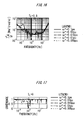
- FIG. 17 is a graph showing coherence of motion control dynamic stiffness by the controller for the power converter according to the embodiment 1 of the present invention.
- FIG. 18 is a graph showing coherence of motion control dynamic stiffness by the controller for the power converter according to the embodiment 1 of the present invention.
- FIG. 19 is a graph showing coherence of motion control dynamic stiffness by the controller for the power converter according to the embodiment 1 of the present invention.
- FIG. 20 is a graph showing speed of the motor not in control by the controller for the power converter according to the embodiment 1 of the present invention, but speed of the motor in control by a back-EMF tracking method.
- FIG. 21 is a graph showing speed of the motor in control by the controller for the power converter according to the embodiment 1 of the present invention.
- FIG. 22 is a graph showing the torque command of the motor not in control by the controller for the power converter according to the embodiment 1 of the present invention, but the torque command of the motor in control by back-EMF tracking method.
- FIG. 23 is a graph showing the torque command of the motor in control by the controller for the power converter according to the embodiment 1 of the present invention.
- FIG. 24 is a graph showing speed of the motor in control by the controller for the power converter according to the embodiment 1 of the present invention.
- FIG. 25 is a graph showing the torque command of the motor in control by the controller for the power converter according to the embodiment 1 of the present invention.
- FIG. 26 is a graph showing the torque command of the motor in control by the controller for the power converter according to the embodiment 1 of the present invention under a step load torque change.
- FIG. 27 is a graph showing the torque command of the motor in control by the controller for the power converter according to the embodiment 1 of the present invention under a step load torque change.
- FIG. 28 is a graph showing the torque command of the motor in control by the controller for the power converter according to the embodiment 1 of the present invention under a step load torque change.
- FIG. 29 is a graph showing speed of the motor in control by the controller for the power converter according to the embodiment 1 of the present invention under a step load torque change.
- FIG. 30 is a graph showing speed of the motor in control by the controller for the power converter according to the embodiment 1 of the present invention under a step load torque change.
- FIG. 31 is a graph showing speed of the motor in control by the controller for the power converter according to the embodiment 1 of the present invention under a step load torque change.
- FIG. 32 is a graph showing a flux command value in control by the controller for the power converter according to the embodiment 1 of the present invention under a step load torque change.
- FIG. 33 is a graph showing a flux command value in control by the controller for the power converter according to the embodiment 1 of the present invention under a step load torque change.
- FIG. 34 is a graph showing a flux command value in control by the controller for the power converter according to the embodiment 1 of the present invention under a step load torque change.
- FIG. 35 is a hardware configuration diagram of the controller for the power converter according to the embodiment 1 of the present invention.
- FIG. 1 is a configuration diagram of a motor system to which a controller for a power converter according to an embodiment 1 of the present invention is applied.
- a motor system 1 includes a motor 2 and a motor driving system 3 .
- An output part of the motor 2 is connected to an input part of a load machine 4 .
- the load machine 4 is an inertia load.
- An input part of the motor driving system 3 is connected to an output part of an AC power supply 5 .
- the AC power supply 5 is a grid.
- the motor driving system 3 includes a diode rectifier 6 , a capacitor 7 , an inverter 8 , a first current detector 9 a , a second current detector 9 b , a first voltage detector 10 a , a second voltage detector 10 b and controller 11 .
- the diode rectifier 6 converts, into DC power, the three-phase AC power supplied from the AC power supply 5 .
- the capacitor 7 is provided across a DC link on the output side of the diode rectifier 6 .
- the capacitor 7 is used to smooth the DC voltage applied to the DC link.
- the inverter 8 is converts the DC power supplied from the diode rectifier 6 into three-phase AC power for driving the induction motor 2 .
- the inverter 8 is a voltage source inverter.
- the inverter 8 is subjected to variable voltage variable frequency (VVVF) control through pulse width modulation (PWM) control.
- VVVF variable voltage variable frequency
- PWM pulse width modulation
- the power conversion circuit of the inverter 8 is formed of three arms.
- One of the arms includes an upper arm and a lower arm.
- the upper and lower arms are each formed of at least one switching element.
- the first current detector 9 a is provided at the v-phase of the output side of the inverter 8 .
- the first current detector 9 a detects the v-phase stator current Ivs.
- the second current detector 9 b is provided at the w-phase of the output side of the inverter 8 .
- the second current detector 9 b detects the v-phase stator current Iws.
- the first voltage detector 10 a is provided at the v-phase of the output side of the inverter 8 .
- the first current detector 10 a detects the v-phase stator voltage Vvs.
- the second voltage detector 10 b is provided at the w-phase of the output side of the inverter 8 .
- the second voltage 10 b detects the v-phase stator voltage Vws.
- the first voltage detector 10 a may be provided between the u-phase and the v-phase of the output side of the inverter 8 . In this case, the first voltage detector 10 a detects the stator line-to-line voltage Vuv.
- the second voltage detector 10 b may be provided between the u-phase and the w-phase of the output side of the inverter 8 . In this case, the second voltage detector 10 b detects the stator line-to line voltage Vuw.
- the controller 11 a speed controller 12 , a brake control switching module 13 , a DB-DTFC calculation module 14 , a first coordinate conversion module 15 , PWM controller 16 , a second coordinate conversion module 17 , a subtraction module 18 , a voltage command value correcting module 19 , a current/flux estimation module 20 and a speed/phase estimation module 21 .
- the speed controller 12 calculates the torque command value T em1 *(k) as s torque command value calculation module so that the rotor angular velocity estimate value rm-r (k) will follow the rotor angular velocity command value * r (k) obtained from an external device.
- the brake control switching module 13 receives the calculated torque command value T em1 *(k) from the speed controller 12 , and receives a preset stator dq-axes flux command value ⁇ qdsl S* (k), a brake preparation flag Fg 1 and a brake start flag Fg 2 .
- the brake control switching module 13 switches the torque command value T em *(k) and the stator dq-axes flux command value ⁇ qds S* (k) to the values used during a normal operation and a braking operation based on the brake preparation flag Fg 1 and the brake start flag Fg 2 obtained from the external device.
- the DB-DTFC calculation module 14 calculates the stator dq-axes voltage command value V qds S* (k) based on the torque command value T em1 *(k), the stator dq-axes flux command value ⁇ qds S* (k), the stator dq-axes flux estimate value ⁇ circumflex over ( ⁇ ) ⁇ qds S (k) and the rotor dq-axes flux estimate value ⁇ circumflex over ( ⁇ ) ⁇ qdr S (k).
- the DB-DTFC calculation module 14 employs, as a control method, a dead-beat direct torque & flux control (DB-DTFC) method.
- V qds _ corrected s* ( k ) V qds s* ( k ) ⁇ V qds _ err s ( k ⁇ 1) (2)
- the current/flux estimation module 20 includes a current observer module 22 , a first flux estimation module 23 and a second flux estimation module 24 .
- the rotor angular velocity estimated value rm-1 is an output of the speed/phase estimation module 21 .
- the rotor dq-axes flux estimate value ⁇ circumflex over ( ⁇ ) ⁇ qdr S an output of the second flux estimation module 24 .
- the proportional gain K 3 , the integral gain K 4 , the estimate value ⁇ circumflex over (R) ⁇ eq of the equivalent resistance, the estimate value ⁇ circumflex over (L) ⁇ r of the rotor winding inductance, the estimate value ⁇ circumflex over (L) ⁇ m of the magnetizing inductance, the rotor resistance ⁇ circumflex over (R) ⁇ r and the inertia moment J, the equivalent time constant ⁇ eq , the control period T and the delay operator z ⁇ 1 are used.
- the current observer module 22 includes a first block 22 a , a second block 22 b , a third block 22 c , a fourth block 22 d , a fifth block 22 e , a sixth block 22 f , and a seventh block 22 g.
- the first block 22 a calculates a value obtained by subtracting the stator dq-axes current estimate value î qds s from the stator dq-axes current measured value i qds s .
- the stator dq-axes current estimate value î qds s is the output of the seventh block 22 g .
- the output of the first block 22 a is input into the second block 22 b and the third block 22 c .
- the second block 22 b is a proportional circuit of gain K 3 .
- the third block 22 c is an integrating circuit of gain K 4 .
- the fourth block calculates a complemented value from a rotor angular velocity estimated value rm-1 and a rotor dq-axes flux estimate value ⁇ qdr S .
- the rotor angular velocity estimated value rm-1 is an output of the speed/phase estimation module 21 .
- the rotor dq-axes flux estimate value ⁇ circumflex over ( ⁇ ) ⁇ qdr S is an output of the second flux estimation module 24 .
- the fourth block 22 d calculates a value obtained by multiplying the rotor dq-axes flux estimate value ⁇ circumflex over ( ⁇ ) ⁇ qdr S by the transfer coefficient G1 expressed by the following equation (3).
- G ⁇ ⁇ 1 L ⁇ m L ⁇ r ⁇ ( R ⁇ r L ⁇ r - J ⁇ ⁇ ⁇ _ rm - 1 ) ( 3 )
- the fifth block 22 e calculates a value obtained by adding the voltage command value (V qds S* ⁇ V qds _ err ) corrected by the voltage command value correcting module 19 , the value calculated by the second block 22 b , the value calculated by the third block 22 c , the value calculated by the fourth block 22 d.
- the sixth block 22 f calculates a value obtained by dividing the value calculated by the fifth block 22 e by the estimate value ⁇ circumflex over (R) ⁇ eq of the equivalent resistance.
- the output of the sixth block 22 f is input into the seventh block 22 g .
- the seventh block 22 g calculates a transfer function expressed in the equation (4).
- the seventh block 22 g outputs a stator dq-axes current estimate value î qds s .
- the stator dq-axes current estimate value î qds s is input into the first block 22 a and the second flux estimation module 24 .
- the first flux estimation module 23 calculates an rotor dq-axes flux estimate value ⁇ circumflex over ( ⁇ ) ⁇ qdr S* based on the rotor angle estimate value ⁇ circumflex over ( ⁇ ) ⁇ r and the stator dq-axes current measured value i qds s .
- the rotor angle estimate value ⁇ circumflex over ( ⁇ ) ⁇ r is an output of the speed/phase estimation module 21 .
- the stator dq-axes current measured value i qds s is an output of the second coordinate conversion module 17 .
- the estimate value ⁇ circumflex over (L) ⁇ m of the magnetizing inductance of the motor 2 , the rotor time constant ⁇ r of the motor 2 , the control period T and the delay operator z ⁇ 1 are used.
- the first flux estimation module 23 includes a first block 23 a , a second block 23 b , and a third block 23 c.
- the first block 23 a converts the stator dq-axes current measured value i qds s to the value of the rotor coordinate system by the rotor angle estimate value ⁇ circumflex over ( ⁇ ) ⁇ r .
- the output of the first block 23 a is the input of the second block 23 b.
- the second block 23 b multiplies the value calculated by the first block 23 a by the transfer function G3 expressed by the following equation (5) to calculate the stator dq-axes flux estimate value of the primary hold.
- G ⁇ ⁇ 3 L ⁇ m ⁇ ⁇ ( 1 - ⁇ r / T + ⁇ r / Te - T / ⁇ r ) + ( ⁇ r / T - ⁇ r / Te - T / ⁇ r - e - T / ⁇ r ) ⁇ z - 1 ⁇ 1 - ( e - T / ⁇ r ) ⁇ z - 1 ( 5 )
- the output of the second block 23 b is the input of the third block 23 c .
- the third block 23 c converts the output of the second block 23 b to the value of the rotor coordinate system by the rotor angle estimate value ⁇ circumflex over ( ⁇ ) ⁇ r .
- the output of the second block 23 b is the rotor dq-axes flux estimate value ⁇ circumflex over ( ⁇ ) ⁇ qdr S* .
- the rotor dq-axes flux estimate value ⁇ circumflex over ( ⁇ ) ⁇ qdr S* is input into second flux estimation module 24 .
- the second flux estimation module 24 calculates a stator dq-axes flux estimate value ⁇ circumflex over ( ⁇ ) ⁇ qds S and a rotor dq-axes flux estimate value ⁇ circumflex over ( ⁇ ) ⁇ qdr S in a subsequent control period based on the voltage command value (V qds S* ⁇ V qds _ err ) corrected by the voltage command value correcting module 19 , the stator dq-axes current measured value i qds s output of the second coordinate conversion module 17 , the stator dq-axes current estimate value î qds s estimated by the current observer module 22 , the rotor dq-axes flux estimate value ⁇ circumflex over ( ⁇ ) ⁇ qdr S* estimated by the first flux estimation module 23 .
- the proportional gain K 1 , the integral gain K 2 , the estimate value ⁇ circumflex over (R) ⁇ s of the stator resistance, the leakage factor ⁇ , the estimate value ⁇ circumflex over (L) ⁇ r of the rotor winding inductance, the estimate value of ⁇ circumflex over (L) ⁇ s of the stator winding inductance, the estimate value ⁇ circumflex over (L) ⁇ m of the magnetizing inductance, the control period T and the delay operator z ⁇ 1 are used.
- the second flux estimation module 24 includes a first block 24 a , a second block 24 b , a third block 24 c , a fourth block 24 d , a fifth block 24 e , a sixth block 24 f , a seventh block 24 g , and a eighth block 24 h , a ninth block 24 i , and a tenth block 24 j.
- the first block 24 a calculates a value of the voltage drop by multiplying the stator dq-axes current measured value i qds s by the estimate value ⁇ circumflex over (R) ⁇ s of the stator resistance.
- the second block 24 b subtracts the rotor dq-axes flux estimate value ⁇ circumflex over ( ⁇ ) ⁇ qdr S which is the output of the tenth block 24 j from the rotor dq-axes flux estimate value ⁇ circumflex over ( ⁇ ) ⁇ qdr S* .
- the third block 24 c calculates a value obtained by subtracting the value calculated by the first block 24 a from the voltage command value (V qds S* ⁇ V qds _ err ) corrected by the voltage command value correcting module 19 .
- the fourth block 24 d , the fifth block 24 e , and the sixth block 24 f function as a transition frequency determination unit 24 k .
- the transition frequency determining unit 24 k determines the transition frequency between the first flux estimation module 23 and the second flux estimation module 24 .
- the seventh block 24 g calculates the stator dq-axes flux estimate value ⁇ circumflex over ( ⁇ ) ⁇ qds S by integrating the output of the sixth block 24 f.
- the eighth block 24 h calculates a value obtained by multiplying the stator dq-axes current estimate value î qds s by the factor G4 expressed by the following equation (6).
- G 4 ⁇ ⁇ circumflex over (L) ⁇ s (6)
- the tenth block 24 j multiplies the value calculated by the ninth block 24 i by the factor G5 expressed by the following equation (7) to calculate the rotor dq-axes flux estimate value ⁇ circumflex over ( ⁇ ) ⁇ qdr S .
- ⁇ ⁇ sl L s ⁇ ( i qs e + ⁇ r ⁇ di qs e d ⁇ ⁇ t ) ⁇ r ⁇ ( ⁇ ds e - ⁇ ⁇ ⁇ L s ⁇ i ds e ) ( 9 )
- the slip angle estimation module 26 calculates a slip angle estimate value ⁇ sl .
- the slip angle estimate value ⁇ sl is calculated by integrating the estimate value sl of the slip frequency.
- the flux vector rotation module 27 calculates an rotor electrical angle estimate value ⁇ circumflex over ( ⁇ ) ⁇ r based on estimate value e j ⁇ e of a phase of the flux vector calculated by the phase estimation module 25 and the slip angle estimate value ⁇ circumflex over ( ⁇ ) ⁇ sl calculated by the slip angle estimation module 26 .
- the third block 29 c corrects the estimated value ⁇ err estimated by the phase error estimation module 28 by multiplying the estimated value ⁇ err estimated by the phase error estimation module 28 and the gain b o .
- the fifth block 29 e calculates a value obtained by adding the value calculated by the fourth block 28 d and the torque command value T em *.
- the seventh block 29 g calculates a rotor mechanical angular velocity estimate value rm-1 .
- the seventh block 29 g is an integrating circuit.
- the seventh block 29 g calculates an integral of the output of the sixth block 29 f.
- the eighth block 29 h calculates the speed correction value by dividing the value calculated by the third block 29 c by the estimated value ⁇ p of the moment of inertia.
- the ninth block 29 i calculates a rotor mechanical angular velocity estimate value rm-r by adding the rotor mechanical angular velocity estimate value rm-1 calculated by the seventh block 29 g and the speed correction value obtained by the eighth block 29 h.
- the tenth block 29 j calculates a rotor mechanical angle estimate value ⁇ circumflex over ( ⁇ ) ⁇ rm .
- the tenth block 29 j is an integrating circuit.
- the seventh block 29 g calculates an integral of the rotor mechanical angular velocity estimate value rm-r .
- the eleventh block 29 k calculates the rotor electrical angle estimate value ⁇ circumflex over ( ⁇ ) ⁇ r by dividing the value obtained by multiplying the rotor mechanical angle estimate value ⁇ circumflex over ( ⁇ ) ⁇ rm calculated by the tenth block 29 j by the number of poles P of the motor 2 by 2.
- FIG. 3 is a graph showing an estimate value of the stator flux of the motor in the case where the voltage command is not corrected by the controller for the power converter according to the embodiment 1 of the present invention.
- FIG. 4 is a graph showing an estimate value of the stator flux of the motor in the case where the voltage command is corrected by the controller for the power converter according to the embodiment 1 of the present invention.
- FIG. 5 to FIG. 7 are graphs showing the estimated speed of the motor controlled by the controller for the power converter according to the embodiment 1 of the present invention.
- FIG. 8 to FIG. 10 are graphs showing comparison of a speed ripple in control by the controller for the power converter according to the embodiment 1 of the present invention and a speed ripple in control by back-EMF tracking method.
- FIG. 11 to FIG. 13 are graphs showing comparison of a torque command ripple in control by the controller for the power converter according to the embodiment 1 of the present invention and a speed ripple in control by a back-EMF tracking method.
- control by the controller 9 reduces the speed ripple compared with the back-EMF tracking method.
- control by the controller 9 reduces the torque command ripple compared with the back-EMF tracking method.
- the operating range in control by the controller 9 is largely extended compared with the back-EMF tracking method.
- FIG. 14 to FIG. 16 are graphs showing the motion control dynamic stiffness of control by the controller for the power converter according to embodiment 1 of the present invention.
- FIG. 17 to FIG. 19 are graphs showing the coherence of the motion control dynamic stiffness by the controller for the power converter according to the embodiment 1 of the present invention.
- the dynamic stiffness is good in 0.01 pu speed of the motor 2 for 0-0.8 pu load conditions. As a result, the tracking for the stator flux of the motor 2 is easier.
- FIG. 20 is a graph showing speed of the motor not in control by the controller for the power converter according to the embodiment 1 of the present invention but speed of the motor in control by a back-EMF tracking method.
- FIG. 21 is a graph showing speed of the motor in control by the controller for the power converter according to the embodiment 1 of the present invention.
- FIG. 22 is a graph showing the torque command of the motor not in control by the controller for the power converter according to the embodiment 1 of the present invention but load torque of the motor in control by a back-EMF tracking method.
- FIG. 23 is a graph showing the torque command of the motor in control by the controller for the power converter according to the embodiment 1 of the present invention.
- FIG. 24 is a graph showing speed of the motor in control by the controller for the power converter according to the embodiment 1 of the present invention.
- FIG. 25 is a graph showing the torque command of the motor in control by the controller for the power converter according to the embodiment 1 of the present invention.
- speed command values change from 0.05 pu to ⁇ 0.05 pu to 0.05 pu with acceleration rate 0.084 pu/s.
- the cross zero speed operation in control by the controller 9 is smooth compared with control by a back-EMF tracking method.
- speed command values change from 0.01 pu to ⁇ 0.01 pu to 0.01 pu with an acceleration rate of 0.034 pu/s.
- the cross zero speed operation in control by the controller 9 is comparatively smooth with a very small acceleration rate.
- FIG. 26 to FIG. 28 are graphs showing the torque command of the motor in control by the controller for the power converter according to the embodiment 1 of the present invention under a step load torque change.
- FIG. 29 to FIG. 31 are graphs showing speed of the motor in control by the controller for the power converter according to the embodiment 1 of the present invention under a step load torque change.
- FIG. 32 to FIG. 34 are graphs showing a flux command value in control by the controller for the power converter according to the embodiment 1 of the present invention under a step load torque change.
- the torque command changes from 0.4 pu to 0.7 pu when the load torque increases.
- the speed of the motor 2 reduces at the moment when the load torque is stepped up, but the speed of the motor 2 tracks the speed command value after short time.
- a flux command value of a stator of the motor 2 is calculated online according to the estimated speed and the load torque conditions to achieve a minimum steady state loss. For example, at a low load torque, the flux command value is small to reduce the total loss. For example, at a high load torque, the flux command value increases.
- the estimate value of the stator flux of the motor 2 is calculated by the corrected voltage command value. Accordingly, the estimation accuracy of a speed of the motor 2 drastically improves. As a result, it is possible to maintain control accuracy in a region of low speed of the motor 2 .
- the current/flux estimation module 18 includes the current observer module 20 , the first flux estimation module 21 and the second flux estimation module 22 . Accordingly, it is possible to calculate the estimate value of the stator flux and rotor flux of the motor 2 more accurately.
- the torque of the motor 2 is estimated based on the estimate value of the stator flux and rotor flux. Accordingly, it is possible to calculate the estimate value of the torque of the motor 2 more accurately.
- FIG. 35 is a hardware configuration diagram of the controller for a power converter according to the embodiment 1 of the present invention.
- each function of the controller 9 is executed by the processing circuit.
- the processing circuit includes a processor 30 a and a memory 30 b.
- the processor 30 a is a central processing unit (CPU), e.g., a central processing device, a processing device, a microprocessor, a microcomputer, a processor or a digital signal processor (DSP).
- CPU central processing unit
- DSP digital signal processor
- the memory 30 b is a non-volatile or volatile semiconductor memory such as RAM, ROM, flash memory, EPROM, EEPROM, or magnetic disk, flexible disk, optical disk, compact disk, mini-disk or DVD.
- a program stored in the memory 30 b is executed by the processor 30 a.
Landscapes
- Engineering & Computer Science (AREA)
- Power Engineering (AREA)
- Control Of Ac Motors In General (AREA)
Abstract
Description

V qsd _ err s(k−1)=V qds s*(k−1)−V qds s(k−1) (1)
V qds _ corrected s*(k)=V qds s*(k)−V qds _ err s(k−1) (2)


G4=σ{circumflex over (L)} s (6)


Claims (3)
Priority Applications (2)
| Application Number | Priority Date | Filing Date | Title |
|---|---|---|---|
| US15/636,916 US10171019B1 (en) | 2017-06-29 | 2017-06-29 | Controller for power converter |
| JP2018003023A JP7028515B2 (en) | 2017-06-29 | 2018-01-12 | Power converter control device and motor drive system |
Applications Claiming Priority (1)
| Application Number | Priority Date | Filing Date | Title |
|---|---|---|---|
| US15/636,916 US10171019B1 (en) | 2017-06-29 | 2017-06-29 | Controller for power converter |
Publications (2)
| Publication Number | Publication Date |
|---|---|
| US10171019B1 true US10171019B1 (en) | 2019-01-01 |
| US20190006971A1 US20190006971A1 (en) | 2019-01-03 |
Family
ID=64739006
Family Applications (1)
| Application Number | Title | Priority Date | Filing Date |
|---|---|---|---|
| US15/636,916 Active US10171019B1 (en) | 2017-06-29 | 2017-06-29 | Controller for power converter |
Country Status (2)
| Country | Link |
|---|---|
| US (1) | US10171019B1 (en) |
| JP (1) | JP7028515B2 (en) |
Cited By (4)
| Publication number | Priority date | Publication date | Assignee | Title |
|---|---|---|---|---|
| CN112311290A (en) * | 2020-10-26 | 2021-02-02 | 江苏大学 | Robust prediction permanent magnet synchronous hub motor sensorless controller |
| US11316391B2 (en) * | 2020-03-02 | 2022-04-26 | GM Global Technology Operations LLC | Closed-loop control for transient operation of variable flux and permanent magnet electric machines |
| US11926221B2 (en) | 2020-09-24 | 2024-03-12 | GM Global Technology Operations LLC | Open-loop control for transient operation of a rotary electric machine |
| US12445074B2 (en) * | 2021-03-18 | 2025-10-14 | Hitachi Astemo, Ltd. | Synchronous machine control device, synchronous machine control method, and electric vehicle |
Families Citing this family (5)
| Publication number | Priority date | Publication date | Assignee | Title |
|---|---|---|---|---|
| US10763769B2 (en) | 2018-06-29 | 2020-09-01 | Wisconsin Alumni Research Foundation | Controller for power convertor and motor driving system |
| US10840841B2 (en) * | 2018-09-27 | 2020-11-17 | Tmeic Corporation | Control device for power conversion device, control method, and motor drive system |
| US11233473B2 (en) | 2019-03-01 | 2022-01-25 | Deere & Company | Method and system for controlling a permanent magnet machine without a mechanical position sensor |
| US11258390B2 (en) * | 2019-07-25 | 2022-02-22 | Wisconsin Alumni Research Foundation | Motor drive system and control method |
| CN122423133A (en) * | 2023-12-05 | 2026-07-17 | 麦格纳国际公司 | System and method for hybrid control of PMSM drivers using two current sensors |
Citations (2)
| Publication number | Priority date | Publication date | Assignee | Title |
|---|---|---|---|---|
| US20010043048A1 (en) * | 2000-03-10 | 2001-11-22 | Fuji Electric Co., Ltd. | Speed sensorless vector control apparatus |
| JP2016010311A (en) | 2014-06-26 | 2016-01-18 | 東芝三菱電機産業システム株式会社 | Control device for power converter |
Family Cites Families (2)
| Publication number | Priority date | Publication date | Assignee | Title |
|---|---|---|---|---|
| JP4533677B2 (en) * | 2004-06-17 | 2010-09-01 | 株式会社東芝 | Power converter |
| JP5910296B2 (en) * | 2012-05-15 | 2016-04-27 | 株式会社デンソー | Induction machine control device |
-
2017
- 2017-06-29 US US15/636,916 patent/US10171019B1/en active Active
-
2018
- 2018-01-12 JP JP2018003023A patent/JP7028515B2/en active Active
Patent Citations (2)
| Publication number | Priority date | Publication date | Assignee | Title |
|---|---|---|---|---|
| US20010043048A1 (en) * | 2000-03-10 | 2001-11-22 | Fuji Electric Co., Ltd. | Speed sensorless vector control apparatus |
| JP2016010311A (en) | 2014-06-26 | 2016-01-18 | 東芝三菱電機産業システム株式会社 | Control device for power converter |
Non-Patent Citations (11)
| Title |
|---|
| Holtz et al., "Drift- and Parameter-Compensated Flux Estimator for Persistent Zero-Stator-Frequency Operation of Sensorless-Controlled Induction Motors," IEEE Transactions on Industry Applications (Jul./Aug. 2003), 39:1052-1060. |
| Holtz, "Sensorless Control of Induction Motor Drives," Proceedings of the IEEE (Aug. 2002), 90:1359-1394. |
| Jansen et al., "A Physically Insightful Approach to the Design and Accuracy Assessment of Flux Observers for Field Oriented Induction Machine Drives," IEEE Transactions on Industry Applications (Jan./Feb. 1994), 30:101-110. |
| Kim et al., "Sensorless Control of Interior Permanent-Magnet Machine Drives With Zero-Phase Lag Position Estimation," IEEE Transactions on Industry Applications (Nov./Dec. 2003), 39:1726-1733. |
| Lorenz et al., "Motion Control with Induction Motors," Proceedings of the IEEE (Aug. 1994), 82:1215-1240. |
| Lorenz, The Emerging Role of Dead-beat, Direct Torque and Flux Control in the Future of Induction Machine Drives, 2008 11th International Conference on Optimization of Electrical and Electronic Equipment (May 2008), pp. 19-27. |
| Schauder, "Adaptive Speed Identification for Vector Control of Induction Motors Without Rotational Transducers," Conference Record of the IEEE Industry Applications Society Annual Meeting (Oct. 1989), pp. 493-499. |
| Shin et al., "An Improved Stator Flux Estimation for Speed Sensorless Stator Flux Orientation Control of Induction Motors," IEEE Transactions on Power Electronics (Mar. 2000), 15:312-318. |
| Vasić et al., "A Stator Resistance Estimation Scheme for Speed Sensorless Rotor Flux Oriented Induction Motor Drives," IEEE Transactions on Energy Conservation (Dec. 2003), 18:476-483. |
| Wang et al., "Loss Manipulation Capabilities of Deadbeat Direct Torque and Flux Control Induction Machine Drives," IEEE Transactions on Industry Applications (Nov./Dec. 2015), 51:4554-4566. |
| Wang et al., "Using Volt-sec. Sensing to Extend the Low Speed Range and the Disturbance Rejection Capability of Back-EMF-based Self-Sensing," 2016 18th European Conference on Power Electronics and Applications (Sep. 2016), pp. 1-10. |
Cited By (5)
| Publication number | Priority date | Publication date | Assignee | Title |
|---|---|---|---|---|
| US11316391B2 (en) * | 2020-03-02 | 2022-04-26 | GM Global Technology Operations LLC | Closed-loop control for transient operation of variable flux and permanent magnet electric machines |
| US11926221B2 (en) | 2020-09-24 | 2024-03-12 | GM Global Technology Operations LLC | Open-loop control for transient operation of a rotary electric machine |
| CN112311290A (en) * | 2020-10-26 | 2021-02-02 | 江苏大学 | Robust prediction permanent magnet synchronous hub motor sensorless controller |
| CN112311290B (en) * | 2020-10-26 | 2022-03-22 | 江苏大学 | A Robust Predictive Sensorless Controller for Permanent Magnet Synchronous In-wheel Motors |
| US12445074B2 (en) * | 2021-03-18 | 2025-10-14 | Hitachi Astemo, Ltd. | Synchronous machine control device, synchronous machine control method, and electric vehicle |
Also Published As
| Publication number | Publication date |
|---|---|
| JP7028515B2 (en) | 2022-03-02 |
| JP2019013129A (en) | 2019-01-24 |
| US20190006971A1 (en) | 2019-01-03 |
Similar Documents
| Publication | Publication Date | Title |
|---|---|---|
| US20190006971A1 (en) | Controller for power converter | |
| US10763769B2 (en) | Controller for power convertor and motor driving system | |
| US8829831B2 (en) | Parameter estimating apparatus for permanent magnet synchronous motor driving system | |
| CN100423446C (en) | Vector Control Device of Permanent Magnet Synchronous Motor | |
| JP3755424B2 (en) | AC motor drive control device | |
| CN101459401B (en) | Position sensorless controller for permanent magnet motor | |
| JP6008264B2 (en) | Magnetic pole position detection device for permanent magnet type synchronous motor | |
| US20190229664A1 (en) | Control apparatus for alternating-current rotary electric machine | |
| JP2010011564A (en) | Controller for permanent magnet synchronous motor and motor control system | |
| EP3537601B1 (en) | Motor control method | |
| US20140225540A1 (en) | Control apparatus for ac motor | |
| KR100921115B1 (en) | Permanent Magnet Synchronous Motor Control System and Control Method | |
| JP5910757B2 (en) | Electric motor control device | |
| US11863093B2 (en) | Motor control device and motor control method | |
| JP5585397B2 (en) | Rotating machine control device | |
| JP4535082B2 (en) | Sensorless control device and control method for synchronous generator | |
| US12143038B2 (en) | Rotary machine control device | |
| JP2004187460A (en) | Inverter control device, induction motor control device, and induction motor system | |
| JP5708373B2 (en) | Rotating machine control device | |
| JP2002325498A (en) | AC motor control device | |
| JP7746950B2 (en) | electric motor | |
| JP5456873B1 (en) | Synchronous machine controller | |
| JP4682521B2 (en) | Variable speed control device for induction motor | |
| WO2024181185A1 (en) | Control device | |
| JP2023177084A (en) | Control device for induction motor |
Legal Events
| Date | Code | Title | Description |
|---|---|---|---|
| AS | Assignment |
Owner name: TOSHIBA MITSUBISHI-ELECTRIC INDUSTRIAL SYSTEMS COR Free format text: ASSIGNMENT OF ASSIGNORS INTEREST;ASSIGNOR:IIDA, RYO;REEL/FRAME:043277/0512 Effective date: 20170621 |
|
| AS | Assignment |
Owner name: WISCONSIN ALUMNI RESEARCH FOUNDATION, WISCONSIN Free format text: ASSIGNMENT OF ASSIGNORS INTEREST;ASSIGNORS:LORENZ, ROBERT;WANG, YUKAI;XU, YANG;SIGNING DATES FROM 20170905 TO 20170912;REEL/FRAME:043677/0223 |
|
| STCF | Information on status: patent grant |
Free format text: PATENTED CASE |
|
| MAFP | Maintenance fee payment |
Free format text: PAYMENT OF MAINTENANCE FEE, 4TH YEAR, LARGE ENTITY (ORIGINAL EVENT CODE: M1551); ENTITY STATUS OF PATENT OWNER: LARGE ENTITY Year of fee payment: 4 |
|
| AS | Assignment |
Owner name: TMEIC CORPORATION, JAPAN Free format text: CHANGE OF NAME;ASSIGNOR:TOSHIBA MITSUBISHI-ELECTRIC INDUSTRIAL SYSTEMS CORPORATION;REEL/FRAME:067244/0359 Effective date: 20240401 |
|
| MAFP | Maintenance fee payment |
Free format text: PAYMENT OF MAINTENANCE FEE, 8TH YEAR, LARGE ENTITY (ORIGINAL EVENT CODE: M1552); ENTITY STATUS OF PATENT OWNER: LARGE ENTITY Year of fee payment: 8 |