US10168527B2 - System and method for simultaneous multi-tube inspection of vertical tube bundles - Google Patents
System and method for simultaneous multi-tube inspection of vertical tube bundles Download PDFInfo
- Publication number
- US10168527B2 US10168527B2 US14/805,936 US201514805936A US10168527B2 US 10168527 B2 US10168527 B2 US 10168527B2 US 201514805936 A US201514805936 A US 201514805936A US 10168527 B2 US10168527 B2 US 10168527B2
- Authority
- US
- United States
- Prior art keywords
- tube
- tubes
- cameras
- video
- defect
- Prior art date
- Legal status (The legal status is an assumption and is not a legal conclusion. Google has not performed a legal analysis and makes no representation as to the accuracy of the status listed.)
- Active, expires
Links
Images


Classifications
-
- G—PHYSICS
- G02—OPTICS
- G02B—OPTICAL ELEMENTS, SYSTEMS OR APPARATUS
- G02B23/00—Telescopes, e.g. binoculars; Periscopes; Instruments for viewing the inside of hollow bodies; Viewfinders; Optical aiming or sighting devices
- G02B23/24—Instruments or systems for viewing the inside of hollow bodies, e.g. fibrescopes
-
- F—MECHANICAL ENGINEERING; LIGHTING; HEATING; WEAPONS; BLASTING
- F22—STEAM GENERATION
- F22B—METHODS OF STEAM GENERATION; STEAM BOILERS
- F22B37/00—Component parts or details of steam boilers
-
- F—MECHANICAL ENGINEERING; LIGHTING; HEATING; WEAPONS; BLASTING
- F22—STEAM GENERATION
- F22B—METHODS OF STEAM GENERATION; STEAM BOILERS
- F22B37/00—Component parts or details of steam boilers
- F22B37/002—Component parts or details of steam boilers specially adapted for nuclear steam generators, e.g. maintenance, repairing or inspecting equipment not otherwise provided for
- F22B37/003—Maintenance, repairing or inspecting equipment positioned in or via the headers
-
- G—PHYSICS
- G01—MEASURING; TESTING
- G01N—INVESTIGATING OR ANALYSING MATERIALS BY DETERMINING THEIR CHEMICAL OR PHYSICAL PROPERTIES
- G01N21/00—Investigating or analysing materials by the use of optical means, i.e. using sub-millimetre waves, infrared, visible or ultraviolet light
- G01N21/84—Systems specially adapted for particular applications
- G01N21/88—Investigating the presence of flaws or contamination
- G01N21/8851—Scan or image signal processing specially adapted therefor, e.g. for scan signal adjustment, for detecting different kinds of defects, for compensating for structures, markings, edges
-
- G—PHYSICS
- G01—MEASURING; TESTING
- G01N—INVESTIGATING OR ANALYSING MATERIALS BY DETERMINING THEIR CHEMICAL OR PHYSICAL PROPERTIES
- G01N21/00—Investigating or analysing materials by the use of optical means, i.e. using sub-millimetre waves, infrared, visible or ultraviolet light
- G01N21/84—Systems specially adapted for particular applications
- G01N21/88—Investigating the presence of flaws or contamination
- G01N21/95—Investigating the presence of flaws or contamination characterised by the material or shape of the object to be examined
- G01N21/954—Inspecting the inner surface of hollow bodies, e.g. bores
-
- G—PHYSICS
- G06—COMPUTING OR CALCULATING; COUNTING
- G06T—IMAGE DATA PROCESSING OR GENERATION, IN GENERAL
- G06T7/00—Image analysis
- G06T7/0002—Inspection of images, e.g. flaw detection
- G06T7/0004—Industrial image inspection
- G06T7/0008—Industrial image inspection checking presence/absence
-
- G—PHYSICS
- G21—NUCLEAR PHYSICS; NUCLEAR ENGINEERING
- G21C—NUCLEAR REACTORS
- G21C17/00—Monitoring; Testing ; Maintaining
- G21C17/017—Inspection or maintenance of pipe-lines or tubes in nuclear installations
-
- G—PHYSICS
- G01—MEASURING; TESTING
- G01N—INVESTIGATING OR ANALYSING MATERIALS BY DETERMINING THEIR CHEMICAL OR PHYSICAL PROPERTIES
- G01N21/00—Investigating or analysing materials by the use of optical means, i.e. using sub-millimetre waves, infrared, visible or ultraviolet light
- G01N21/84—Systems specially adapted for particular applications
- G01N21/88—Investigating the presence of flaws or contamination
- G01N21/8851—Scan or image signal processing specially adapted therefor, e.g. for scan signal adjustment, for detecting different kinds of defects, for compensating for structures, markings, edges
- G01N2021/8854—Grading and classifying of flaws
-
- G—PHYSICS
- G01—MEASURING; TESTING
- G01N—INVESTIGATING OR ANALYSING MATERIALS BY DETERMINING THEIR CHEMICAL OR PHYSICAL PROPERTIES
- G01N21/00—Investigating or analysing materials by the use of optical means, i.e. using sub-millimetre waves, infrared, visible or ultraviolet light
- G01N21/84—Systems specially adapted for particular applications
- G01N21/88—Investigating the presence of flaws or contamination
- G01N21/95—Investigating the presence of flaws or contamination characterised by the material or shape of the object to be examined
- G01N21/954—Inspecting the inner surface of hollow bodies, e.g. bores
- G01N2021/9542—Inspecting the inner surface of hollow bodies, e.g. bores using a probe
-
- G—PHYSICS
- G01—MEASURING; TESTING
- G01N—INVESTIGATING OR ANALYSING MATERIALS BY DETERMINING THEIR CHEMICAL OR PHYSICAL PROPERTIES
- G01N21/00—Investigating or analysing materials by the use of optical means, i.e. using sub-millimetre waves, infrared, visible or ultraviolet light
- G01N21/84—Systems specially adapted for particular applications
- G01N21/88—Investigating the presence of flaws or contamination
- G01N21/95—Investigating the presence of flaws or contamination characterised by the material or shape of the object to be examined
- G01N21/954—Inspecting the inner surface of hollow bodies, e.g. bores
- G01N2021/9548—Scanning the interior of a cylinder
-
- G—PHYSICS
- G06—COMPUTING OR CALCULATING; COUNTING
- G06T—IMAGE DATA PROCESSING OR GENERATION, IN GENERAL
- G06T2207/00—Indexing scheme for image analysis or image enhancement
- G06T2207/10—Image acquisition modality
- G06T2207/10016—Video; Image sequence
-
- G—PHYSICS
- G06—COMPUTING OR CALCULATING; COUNTING
- G06T—IMAGE DATA PROCESSING OR GENERATION, IN GENERAL
- G06T2207/00—Indexing scheme for image analysis or image enhancement
- G06T2207/30—Subject of image; Context of image processing
- G06T2207/30108—Industrial image inspection
-
- Y—GENERAL TAGGING OF NEW TECHNOLOGICAL DEVELOPMENTS; GENERAL TAGGING OF CROSS-SECTIONAL TECHNOLOGIES SPANNING OVER SEVERAL SECTIONS OF THE IPC; TECHNICAL SUBJECTS COVERED BY FORMER USPC CROSS-REFERENCE ART COLLECTIONS [XRACs] AND DIGESTS
- Y02—TECHNOLOGIES OR APPLICATIONS FOR MITIGATION OR ADAPTATION AGAINST CLIMATE CHANGE
- Y02E—REDUCTION OF GREENHOUSE GAS [GHG] EMISSIONS, RELATED TO ENERGY GENERATION, TRANSMISSION OR DISTRIBUTION
- Y02E30/00—Energy generation of nuclear origin
- Y02E30/30—Nuclear fission reactors
Definitions
- the present invention relates generally to visual inspection of tubes in a vertical tube bundle. More particularly, the present invention relates to simultaneous visually inspection of multiple vertical tubes of a tubular reactor.
- each tube must be examined for scaling, cracks or ruptures.
- the tube bundles are oriented vertically. Thus, the inspection requires an individual in the lower head to shine a light through each individual tub while a second individual looks down that same tube to identify any defects or plugging. If defects are located, the tube can be blocked off at the top and bottom ends or marked for cleaning or other treatment. Once cleaned, the tube must be reinspected.
- the present invention achieves its objectives by providing a system and method for simultaneously inspecting multiple tubes in these vertical tube bundles.
- the pressure vessel is taken out of service and the catalyst and any other structures are removed from the tube bundle.
- a multi-tube inspection system with a reel having a plurality of cameras is placed in the upper header. Each camera is attached to its own lead line and has a light source.
- An inspector located in the upper header, aligns each camera with a tube and then operates the reel to simultaneously lower the cameras through their respective tube.
- the video image is stored and relayed to a control center where additional inspectors can review the video image of the interior of the tube.
- Each video is identified and tied back to the tube in a data base. If a defect is identified, the tube can be taken out of service (blocked off) or scheduled for cleaning. Once cleaned, the tube is then reinspected.
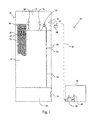
- FIG. 1 is a schematic view showing the multi-tube inspection process and system
- FIG. 2 is a flow diagram showing the multi-tube inspection process
- FIG. 3 is an exploded view of the multi-tube inspection system
- FIG. 4 is a sectional view of the multi-tube inspection system
- FIG. 5 is an end view of the base of the multi-tube inspection system
- FIG. 6 is a top view of the multi-tube inspection system
- FIG. 7 is a front view of the multi-tube inspection system
- FIG. 8 is an end view of the multi-tube inspection system.
- FIG. 9 is an end view of the base of the multi-tube inspection system.
- FIG. 1 is a schematic of the system and method of the present invention for inspecting vertically oriented tube bundles 10 typically found in tubular reactors 12 .
- a typical reactor 12 may have as many as 5,000 to 10,000 individual tubes 14 .
- These tubes 14 are typically 20 to 40 feet in length with manway 16 access to the headers 18 at the top and bottom of the tube bundle 10 .
- the area and volume in these headers 18 vary but are typically large enough to hold two to four inspectors and the equipment disclosed in this application.
- these tubes 14 contain catalyst.
- Various petroleum products flow through these tubes 14 where the product is further refined through reaction with the catalyst.
- the reactors 12 are taken out of production on a periodic basis to remove the used catalyst, inspect and repair damaged tubes 14 and then refilled with new catalyst.
- the present invention includes an inspection process of simultaneously lowering a plurality of cameras 20 , each with a light source 22 , down a plurality of tubes 14 in the bundle 10 . Thus, each camera 20 passes through a separate tube 14 .
- the reactor 12 Once the reactor 12 is taken out of service, the remaining petrochemicals are drained. The manways 16 to the upper and lower headers 18 are opened and the reactor 12 is ventilated. Crews then enter the headers 18 and remove the catalyst from the tubes 14 . This is accomplished in a manner known in the industry.
- the inspection crew consisting of one or more inspectors 24 , each with a multi-tube inspection system 26 , enter the upper header 18 .
- the legs 28 of the stand 30 and drum 32 can be removed from the base 34 , if needed, to fit it through the manway 16 .
- the stand 30 , drum 32 and cameras 20 are assembled on the base 34 .
- the inspector 24 then lowers two or more cameras 20 down two or more tubes 14 .
- each of the two or more tubes 14 being inspected has a camera 20 and light source 22 passing through it.
- the preferred embodiment shows 16 individual reels 36 each with its own camera 20 , light source 22 and lead line 38 .
- the drum 32 is rotated allowing the cameras 20 and light source 22 to lower each through an individual tube 14 as the lead lines 38 are unspooled from their individual reels 36 and pass through the adjustable guide jig 40 .
- the drums 32 are mounted on a common axis 72 such that rotation of one drum 32 causes rotation of the other drums 32 on the axis 72 .
- the video signal 42 is transmitted up the lead lines 38 to the camera control unit 44 .
- the video signal 42 is then transmitted, preferably wirelessly, to a control center 46 where the video footage of the tubes 14 can be examined by a supervising technician or engineer 48 .
- a tube 14 is determined to need further work to remedy a problem, it is blocked with a cap 50 which has an RFID marker 52 that is assigned a unique identifier 54 .
- a database 56 can then be maintained to identify the exact tube 14 and its deficiencies.
- Tubes 14 that are deemed acceptable are provided with a cap 50 which may not have an RFID marker 52 .
- the caps 50 of the deficient and acceptable tubes 14 may be further differentiated by using different colored caps 50 , such as red for deficient tubes 14 and green for acceptable tubes 14 .
- a deficient tube 14 When a deficient tube 14 has been worked on to remove the deficiency, it is re-inspected. If the deficiency has been resolved, the tube 14 receives a green cap 50 and the correction is noted in the database 56 . If the deficiency remains, the red cap 50 is reinstalled. The further deficiency is noted in the database 56 .
- the tube 14 may receive further work and re-inspection or be taken out of service. In order to take a tube 14 out of service, both ends of the tube 14 must be blocked off to prevent liquids from entering the tube 14 .
- the multi-tube inspection system 26 has a stand 30 with a base 34 having removable legs 28 .
- the length of the legs 28 , and in turn, the height of the stand 30 can be adjusted.
- a drum 32 having a plurality of reels 36 is rotatably mounted on the stand 30 . In the preferred embodiment shown in the drawings, this rotatable mounting is accomplished by the drum 32 riding on a plurality of rollers 58 . Thus, the drums 32 have a common axis of rotation 72 .
- the drums 32 are also engaged with a variable speed drive motor 60 . When energized, the variable speed drive motor 60 causes the drums 32 to rotate about the axis of oration 72 . It should be noted that the drums 32 could be rotatably mounted to the stand 30 in other ways. Further, the rotation of the drum 32 could be induced by other mechanisms, including but not limited to, being manually rotated by hand.
- Each reel 36 has a lead line 38 that electronically connects a camera 20 and light source 22 to a power source 62 . It also provides a path for the video signal 42 from the camera 20 to the camera control unit 44 .
- Each lead line 38 passes though one of the guides 64 on the guide jig 40 as it is raised and lowered. The guides 64 can be adjusted along the guide jig 40 to match the spacing between the tubes 14 in the tube bundle 10 .
- the camera control unit 44 and battery 66 are located inside the drum 32 . This keeps the system 26 as compact as possible.
- the battery 66 provides power to the cameras 20 , light sources 22 , variable speed drive 60 and camera control unit 44 .
- the camera control unit 44 provides DVR storage of the video signal 42 . It also provides a Wi-Fi or other wireless connection to the control center 46 . In some applications, it may be necessary to provide a wireless router 68 or repeater just inside or just outside the manway 16 in order to get the wireless signal to the control center 46 .
- the video signal 42 of each tube 14 inspected is reviewed on a computer 70 or other video display device by a supervising engineer or technician 48 in the control center 46 .
- Additional features to the present invention may include, but are not limited to, the use of a Unique Tube Identification Software (UTIS).
- UTIS Unique Tube Identification Software
- the UTIS software will assist in generating reports for each inspected tube. This may include listing of physical tube asset management or unique address, tube conditions, residue identification, rust and hot spot locations on each tube.
- the report may also include the location of the defect or abnormality within the tube.
Landscapes
- Physics & Mathematics (AREA)
- Engineering & Computer Science (AREA)
- General Physics & Mathematics (AREA)
- General Engineering & Computer Science (AREA)
- High Energy & Nuclear Physics (AREA)
- Mechanical Engineering (AREA)
- Thermal Sciences (AREA)
- Chemical & Material Sciences (AREA)
- Life Sciences & Earth Sciences (AREA)
- General Health & Medical Sciences (AREA)
- Analytical Chemistry (AREA)
- Immunology (AREA)
- Pathology (AREA)
- Biochemistry (AREA)
- Health & Medical Sciences (AREA)
- Computer Vision & Pattern Recognition (AREA)
- Plasma & Fusion (AREA)
- Optics & Photonics (AREA)
- Astronomy & Astrophysics (AREA)
- Signal Processing (AREA)
- Theoretical Computer Science (AREA)
- Quality & Reliability (AREA)
- Investigating Materials By The Use Of Optical Means Adapted For Particular Applications (AREA)
- Monitoring And Testing Of Nuclear Reactors (AREA)
Abstract
Description
Claims (6)
Priority Applications (2)
| Application Number | Priority Date | Filing Date | Title |
|---|---|---|---|
| US14/805,936 US10168527B2 (en) | 2014-07-22 | 2015-07-22 | System and method for simultaneous multi-tube inspection of vertical tube bundles |
| US16/203,044 US20190094514A1 (en) | 2014-07-22 | 2018-11-28 | System for simultaneous multi-tube inspection of vertical tube bundles |
Applications Claiming Priority (2)
| Application Number | Priority Date | Filing Date | Title |
|---|---|---|---|
| US201462027480P | 2014-07-22 | 2014-07-22 | |
| US14/805,936 US10168527B2 (en) | 2014-07-22 | 2015-07-22 | System and method for simultaneous multi-tube inspection of vertical tube bundles |
Related Child Applications (1)
| Application Number | Title | Priority Date | Filing Date |
|---|---|---|---|
| US16/203,044 Continuation US20190094514A1 (en) | 2014-07-22 | 2018-11-28 | System for simultaneous multi-tube inspection of vertical tube bundles |
Publications (2)
| Publication Number | Publication Date |
|---|---|
| US20160025961A1 US20160025961A1 (en) | 2016-01-28 |
| US10168527B2 true US10168527B2 (en) | 2019-01-01 |
Family
ID=53801175
Family Applications (2)
| Application Number | Title | Priority Date | Filing Date |
|---|---|---|---|
| US14/805,936 Active 2036-11-05 US10168527B2 (en) | 2014-07-22 | 2015-07-22 | System and method for simultaneous multi-tube inspection of vertical tube bundles |
| US16/203,044 Abandoned US20190094514A1 (en) | 2014-07-22 | 2018-11-28 | System for simultaneous multi-tube inspection of vertical tube bundles |
Family Applications After (1)
| Application Number | Title | Priority Date | Filing Date |
|---|---|---|---|
| US16/203,044 Abandoned US20190094514A1 (en) | 2014-07-22 | 2018-11-28 | System for simultaneous multi-tube inspection of vertical tube bundles |
Country Status (2)
| Country | Link |
|---|---|
| US (2) | US10168527B2 (en) |
| WO (1) | WO2016014697A1 (en) |
Cited By (2)
| Publication number | Priority date | Publication date | Assignee | Title |
|---|---|---|---|---|
| US11150218B2 (en) | 2018-05-30 | 2021-10-19 | Amerapex NDT LLC | Parallel tube inspection system |
| US12339073B2 (en) | 2021-05-11 | 2025-06-24 | Arkema Inc. | Method for monitoring a tube sheet of a heat exchanger |
Families Citing this family (6)
| Publication number | Priority date | Publication date | Assignee | Title |
|---|---|---|---|---|
| US11111773B1 (en) * | 2020-06-18 | 2021-09-07 | Saudi Arabian Oil Company | Systems and methods for testing wellbore completion systems |
| CN117642248A (en) * | 2021-05-11 | 2024-03-01 | 阿科玛股份有限公司 | Method for monitoring tube segments of a heat exchanger |
| CN114527130A (en) * | 2021-12-27 | 2022-05-24 | 杭州安脉盛智能技术有限公司 | Cylindrical fuel rod cluster outer ring surface defect detection device |
| US12345154B2 (en) | 2022-09-14 | 2025-07-01 | Saudi Arabian Oil Company | Untethered logging devices and related methods of logging a wellbore |
| US11913329B1 (en) | 2022-09-21 | 2024-02-27 | Saudi Arabian Oil Company | Untethered logging devices and related methods of logging a wellbore |
| US12486762B2 (en) | 2024-01-11 | 2025-12-02 | Saudi Arabian Oil Company | Systems and methods for untethered wellbore investigation using modular autonomous device |
Citations (32)
| Publication number | Priority date | Publication date | Assignee | Title |
|---|---|---|---|---|
| US4249413A (en) | 1977-11-22 | 1981-02-10 | Electricite De France (Service National) | Method and device for locating a defective tube in a steam generator tube bundle |
| US4319840A (en) | 1978-04-21 | 1982-03-16 | Ngk Insulators, Ltd. | Method and a device for inspecting bodies having a multiplicity of parallel channels extending therethrough |
| US5083606A (en) | 1990-08-09 | 1992-01-28 | Texas Utilities Electric Company | Structure and method for on-line inspection of condenser tubes |
| US5091141A (en) | 1989-05-23 | 1992-02-25 | Framatome | Device for inserting and positioning a tool inside a heat exchanger and use of this device |
| US5105876A (en) | 1989-07-06 | 1992-04-21 | Westinghouse Electric Corp. | Multiple-unit probe pusher and system for driving eddy current inspection probes in the heat exchanger tubes of a nuclear steam generator |
| EP0501648A2 (en) | 1991-02-27 | 1992-09-02 | Electric Power Research Institute, Inc | In bundle foreign object search and retrieval apparatus |
| WO1995009323A1 (en) | 1993-09-30 | 1995-04-06 | Combustion Engineering, Inc. | Multi-tube high speed rotating probe |
| WO1995019526A1 (en) | 1994-01-14 | 1995-07-20 | Combustion Engineering, Inc. | Dual guide tube for inspection of heat exchangers |
| US5956135A (en) * | 1997-11-03 | 1999-09-21 | Quesnel; Ray J. | Pipeline inspection apparatus |
| JP2002243650A (en) | 2001-02-19 | 2002-08-28 | Cataler Corp | Method and device for inspecting cell clogging |
| US20030052967A1 (en) | 2001-09-19 | 2003-03-20 | Brunton Adrian Bruce | Video inspection apparatus |
| US20040134518A1 (en) * | 2002-12-23 | 2004-07-15 | Catalyst Services, Inc. | Cleaning and/or inspecting robot for hazardous environments including catalyst removal |
| US20040189987A1 (en) | 2000-11-15 | 2004-09-30 | Quest Integrated Inc. | A method for reformer tube in situ inspection radius calculation |
| US20050126597A1 (en) | 2003-12-11 | 2005-06-16 | Hochstein James R.Jr. | Inspection camera |
| JP2005201664A (en) | 2004-01-13 | 2005-07-28 | Babcock Hitachi Kk | Inspection device of tube bundle |
| US20050183028A1 (en) * | 2003-09-11 | 2005-08-18 | Clough Bradford A. | System and method for acquisition and analysis of time and location-specific data |
| US20060191119A1 (en) | 2005-02-28 | 2006-08-31 | Electric Power Research Institute, Inc. | Method for inspection and repair |
| US20070083398A1 (en) * | 2005-10-07 | 2007-04-12 | Veolia Es Industrial Services, Inc. | System to manage maintenance of a pipeline structure, program product, and related methods |
| US20080210024A1 (en) * | 2007-02-28 | 2008-09-04 | Merlo Stephen A | Remote pipe inspection |
| US20090095211A1 (en) * | 2007-10-11 | 2009-04-16 | Tubemaster, Inc. | Device and method for indicating the condition of tubes on a tubesheet |
| US7673496B2 (en) | 2001-03-16 | 2010-03-09 | Tubemaster Inc | Device for measuring back pressure in chemical reactor tubes |
| US20100063304A1 (en) | 2008-09-09 | 2010-03-11 | Basf Se | Apparatus for automatic catalyst exchange in a reactor with a bundle of catalyst tubes |
| US20110108654A1 (en) * | 2009-11-11 | 2011-05-12 | Emerson Electric Co. | Reel frames for remote video inspection systems |
| US20120147173A1 (en) * | 2010-12-10 | 2012-06-14 | Lynch Christopher J | Hand-carryable pushrod-based camera system |
| US20120162408A1 (en) | 2010-12-23 | 2012-06-28 | Silviu Zilberman | Method and system for drafting a map for a "tube-sheet" |
| US20120193065A1 (en) * | 2011-02-02 | 2012-08-02 | Mitsubishi Heavy Industries, Ltd. | Inspection apparatus and inspection method for heat transfer tube |
| US8547428B1 (en) * | 2006-11-02 | 2013-10-01 | SeeScan, Inc. | Pipe mapping system |
| US20140125791A1 (en) * | 2012-11-07 | 2014-05-08 | Solar Turbines Incorporated | Combustor imaging inspection system |
| US20140147086A1 (en) * | 2012-05-01 | 2014-05-29 | Eric M. Chapman | High bandwidth push cables for video pipe inspection systems |
| US20140184794A1 (en) | 2012-12-31 | 2014-07-03 | General Electric Company | Inspection systems and methods |
| US20140253715A1 (en) * | 2013-03-09 | 2014-09-11 | Olympus Corporation | Photography system and photography method |
| US20150341600A1 (en) * | 2014-05-22 | 2015-11-26 | Siemens Energy, Inc. | Flexible tether position tracking camera inspection system for visual inspection of off line industrial gas turbines and other power generation machinery |
Family Cites Families (4)
| Publication number | Priority date | Publication date | Assignee | Title |
|---|---|---|---|---|
| US5490185A (en) * | 1993-07-23 | 1996-02-06 | Westinghouse Electric Corporation | System for automatic refueling of a nuclear reactor |
| US7187784B2 (en) * | 1998-09-30 | 2007-03-06 | Florida State University Research Foundation, Inc. | Borescope for drilled shaft inspection |
| JP2002168992A (en) * | 2000-11-30 | 2002-06-14 | Hitachi Ltd | Repair method and repair device in reactor pressure vessel |
| US10395785B2 (en) * | 2014-05-19 | 2019-08-27 | Nuscale Power, Llc | Transportable monitoring system |
-
2015
- 2015-07-22 US US14/805,936 patent/US10168527B2/en active Active
- 2015-07-22 WO PCT/US2015/041590 patent/WO2016014697A1/en not_active Ceased
-
2018
- 2018-11-28 US US16/203,044 patent/US20190094514A1/en not_active Abandoned
Patent Citations (34)
| Publication number | Priority date | Publication date | Assignee | Title |
|---|---|---|---|---|
| US4249413A (en) | 1977-11-22 | 1981-02-10 | Electricite De France (Service National) | Method and device for locating a defective tube in a steam generator tube bundle |
| US4319840A (en) | 1978-04-21 | 1982-03-16 | Ngk Insulators, Ltd. | Method and a device for inspecting bodies having a multiplicity of parallel channels extending therethrough |
| US5091141A (en) | 1989-05-23 | 1992-02-25 | Framatome | Device for inserting and positioning a tool inside a heat exchanger and use of this device |
| US5105876A (en) | 1989-07-06 | 1992-04-21 | Westinghouse Electric Corp. | Multiple-unit probe pusher and system for driving eddy current inspection probes in the heat exchanger tubes of a nuclear steam generator |
| US5083606A (en) | 1990-08-09 | 1992-01-28 | Texas Utilities Electric Company | Structure and method for on-line inspection of condenser tubes |
| EP0501648A2 (en) | 1991-02-27 | 1992-09-02 | Electric Power Research Institute, Inc | In bundle foreign object search and retrieval apparatus |
| WO1995009323A1 (en) | 1993-09-30 | 1995-04-06 | Combustion Engineering, Inc. | Multi-tube high speed rotating probe |
| WO1995019526A1 (en) | 1994-01-14 | 1995-07-20 | Combustion Engineering, Inc. | Dual guide tube for inspection of heat exchangers |
| US5956135A (en) * | 1997-11-03 | 1999-09-21 | Quesnel; Ray J. | Pipeline inspection apparatus |
| US20050237519A1 (en) | 2000-11-15 | 2005-10-27 | Quest Trutec, Lp | Method and apparatus for in situ inspection of reformer tubes |
| US7046356B2 (en) | 2000-11-15 | 2006-05-16 | Quest Trutec, Lp | Method for processing in situ inspection reformer tube data |
| US20040189987A1 (en) | 2000-11-15 | 2004-09-30 | Quest Integrated Inc. | A method for reformer tube in situ inspection radius calculation |
| JP2002243650A (en) | 2001-02-19 | 2002-08-28 | Cataler Corp | Method and device for inspecting cell clogging |
| US7673496B2 (en) | 2001-03-16 | 2010-03-09 | Tubemaster Inc | Device for measuring back pressure in chemical reactor tubes |
| US20030052967A1 (en) | 2001-09-19 | 2003-03-20 | Brunton Adrian Bruce | Video inspection apparatus |
| US20040134518A1 (en) * | 2002-12-23 | 2004-07-15 | Catalyst Services, Inc. | Cleaning and/or inspecting robot for hazardous environments including catalyst removal |
| US20050183028A1 (en) * | 2003-09-11 | 2005-08-18 | Clough Bradford A. | System and method for acquisition and analysis of time and location-specific data |
| US20050126597A1 (en) | 2003-12-11 | 2005-06-16 | Hochstein James R.Jr. | Inspection camera |
| JP2005201664A (en) | 2004-01-13 | 2005-07-28 | Babcock Hitachi Kk | Inspection device of tube bundle |
| US20060191119A1 (en) | 2005-02-28 | 2006-08-31 | Electric Power Research Institute, Inc. | Method for inspection and repair |
| US20070083398A1 (en) * | 2005-10-07 | 2007-04-12 | Veolia Es Industrial Services, Inc. | System to manage maintenance of a pipeline structure, program product, and related methods |
| US8547428B1 (en) * | 2006-11-02 | 2013-10-01 | SeeScan, Inc. | Pipe mapping system |
| US20080210024A1 (en) * | 2007-02-28 | 2008-09-04 | Merlo Stephen A | Remote pipe inspection |
| US20090095211A1 (en) * | 2007-10-11 | 2009-04-16 | Tubemaster, Inc. | Device and method for indicating the condition of tubes on a tubesheet |
| US20100063304A1 (en) | 2008-09-09 | 2010-03-11 | Basf Se | Apparatus for automatic catalyst exchange in a reactor with a bundle of catalyst tubes |
| US20110108654A1 (en) * | 2009-11-11 | 2011-05-12 | Emerson Electric Co. | Reel frames for remote video inspection systems |
| US20120147173A1 (en) * | 2010-12-10 | 2012-06-14 | Lynch Christopher J | Hand-carryable pushrod-based camera system |
| US20120162408A1 (en) | 2010-12-23 | 2012-06-28 | Silviu Zilberman | Method and system for drafting a map for a "tube-sheet" |
| US20120193065A1 (en) * | 2011-02-02 | 2012-08-02 | Mitsubishi Heavy Industries, Ltd. | Inspection apparatus and inspection method for heat transfer tube |
| US20140147086A1 (en) * | 2012-05-01 | 2014-05-29 | Eric M. Chapman | High bandwidth push cables for video pipe inspection systems |
| US20140125791A1 (en) * | 2012-11-07 | 2014-05-08 | Solar Turbines Incorporated | Combustor imaging inspection system |
| US20140184794A1 (en) | 2012-12-31 | 2014-07-03 | General Electric Company | Inspection systems and methods |
| US20140253715A1 (en) * | 2013-03-09 | 2014-09-11 | Olympus Corporation | Photography system and photography method |
| US20150341600A1 (en) * | 2014-05-22 | 2015-11-26 | Siemens Energy, Inc. | Flexible tether position tracking camera inspection system for visual inspection of off line industrial gas turbines and other power generation machinery |
Cited By (2)
| Publication number | Priority date | Publication date | Assignee | Title |
|---|---|---|---|---|
| US11150218B2 (en) | 2018-05-30 | 2021-10-19 | Amerapex NDT LLC | Parallel tube inspection system |
| US12339073B2 (en) | 2021-05-11 | 2025-06-24 | Arkema Inc. | Method for monitoring a tube sheet of a heat exchanger |
Also Published As
| Publication number | Publication date |
|---|---|
| US20160025961A1 (en) | 2016-01-28 |
| US20190094514A1 (en) | 2019-03-28 |
| WO2016014697A1 (en) | 2016-01-28 |
| WO2016014697A9 (en) | 2016-09-15 |
Similar Documents
| Publication | Publication Date | Title |
|---|---|---|
| US10168527B2 (en) | System and method for simultaneous multi-tube inspection of vertical tube bundles | |
| US7265662B2 (en) | Apparatus and method for inspecting containers | |
| US20160203593A1 (en) | Method and device for testing an inspection system for detecting surface defects | |
| DE10163038T1 (en) | Catalyst loading system | |
| US12515935B2 (en) | Method for product guidance in a filling system and filling system for glass bottles | |
| US20150085290A1 (en) | Fluid analysis | |
| JP7221419B2 (en) | Inspection system, judgment processing device, and inspection method | |
| US20180149551A1 (en) | Oil leakage detection device | |
| US20240165731A1 (en) | Welding data processing device and welding data processing method | |
| US12597108B2 (en) | Method and apparatus to perform a wireline cable inspection | |
| JP2017207323A (en) | Image processing water quality monitoring system | |
| DE102014107671A1 (en) | Test system for a pressure system with a pressure vessel and strength test method for a pressure system with a pressure vessel | |
| US7822273B1 (en) | Method and apparatus for automatic corrosion detection via video capture | |
| CN207760163U (en) | A kind of drinking water system that band remotely monitors | |
| JP2012058245A (en) | Photographic survey system and method usable in nuclear reactor | |
| KR101281141B1 (en) | Inner wall surface inspection device of vessel | |
| JP5016195B2 (en) | X-ray liquid level inspection system | |
| CN114535109A (en) | Electroplating appearance automated inspection screening installation | |
| JP5571023B2 (en) | Identification number inspection method for cylindrical containers | |
| CN118071186A (en) | Automatic monitoring system for appearance of formation foil surface | |
| JP6806131B2 (en) | Gas station system | |
| JP6097755B2 (en) | Verification of scope of automated analysis (AACV) | |
| RU2475380C2 (en) | Method of in-place repair of complex systems of weapons and combat equipment | |
| CN115796792B (en) | A lifecycle tracking management system for pipelines | |
| DE102016117813A1 (en) | A portable apparatus for diagnosing a process fluid carrying actuator and method for diagnosing the condition of a process fluid carrying actuator |
Legal Events
| Date | Code | Title | Description |
|---|---|---|---|
| AS | Assignment |
Owner name: CLEARWATER DOWNSTREAM SERVICES, LLC, OKLAHOMA Free format text: ASSIGNMENT OF ASSIGNORS INTEREST;ASSIGNOR:TRIPATHY, KISHLAY;REEL/FRAME:036159/0988 Effective date: 20141015 |
|
| STCF | Information on status: patent grant |
Free format text: PATENTED CASE |
|
| MAFP | Maintenance fee payment |
Free format text: PAYMENT OF MAINTENANCE FEE, 4TH YR, SMALL ENTITY (ORIGINAL EVENT CODE: M2551); ENTITY STATUS OF PATENT OWNER: SMALL ENTITY Year of fee payment: 4 |
|
| AS | Assignment |
Owner name: MILLBROS GROUP, LLC, OKLAHOMA Free format text: ASSIGNMENT OF ASSIGNORS INTEREST;ASSIGNOR:CLEARWATER DOWNSTREAM SERVICES, LLC;REEL/FRAME:068558/0825 Effective date: 20240903 |