RELATED APPLICATIONS
The present application is a National Phase of International Application No. PCT/JP2015/081075, filed Nov. 4, 2015, and claims priority based on Japanese Patent Application Nos. 2014-224623 and 2014-224630, filed Nov. 4, 2014.
TECHNICAL FIELD
The present invention relates to a cylinder device and a cover member.
BACKGROUND ART
For example, at a strut-type shock absorber described in JP2003-65381A, a dust boot as a cover member is held to a bump cap, such that a convex portion at an inner periphery of the dust boot is locked to a flange portion disposed at an outer periphery of the bump cap.
The above-described dust boot includes a thin-walled skirt portion at an end portion, and includes the convex portion locked to the flange portion of the bump cap at an inner periphery of the skirt portion. In view of this, when the dust boot is fitted into the bump cap to press the dust boot to the flange portion, the skirt portion elastically deforms to radially expand, and then, after the convex portion has climbed over the flange portion, the skirt portion radially reduces. This locks the convex portion of the dust boot to the flange portion of the bump cap. Thus, the above-described dust boot can be easily attached to the bump cap such that the skirt portion deforms.
SUMMARY OF INVENTION
However, according to the strut-type shock absorber, there may be a case where the dust boot cannot be attached to the bump cap unless after a coil spring and a mount member are attached to a cylinder.
In this case, a worker inserts a finger into a clearance of the coil spring to press the dust boot to the bump cap only with fingertip force. Thus, even with the above-described technique, it is difficult to attach the dust boot to the bump cap.
It is an object of the present invention to improve attachability of a cover member.
According to one aspect of the present invention, a cylinder device includes a cylinder that has one end from which a piston rod extends, a pipe-shaped cover member that has an extendable bellows portion and a small-diameter portion whose inner diameter is smaller than an inner diameter of the bellows portion, the cover member being configured to protect the piston rod, and a capping member fitted into the cylinder, the capping member having a convex portion to which the small-diameter portion of the cover member is locked, at an outer periphery, wherein at the small-diameter portion of the cover member, a bulge portion that bulges outside in a radial direction is formed.
According to another aspect of the present invention, a cover member includes an extendable pipe-shaped bellows portion, a small-diameter portion locked to a convex portion disposed at an outer periphery of a protected body, an inner diameter of the small-diameter portion being smaller than an inner diameter of the bellows portion, and a bulge portion formed at the small-diameter portion to bulge outside in a radial direction.
BRIEF DESCRIPTION OF DRAWINGS
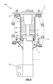
FIG. 1 is a partial cross-sectional view of a shock absorber according to a first embodiment of the present invention.
FIG. 2 is a cross-sectional view at a convex portion of a bump cap.
FIG. 3 is a drawing of a dust boot viewed from a small-diameter portion side.
FIG. 4 is a drawing for describing a bulge portion of the dust boot.
FIG. 5 is a partial cross-sectional view of a shock absorber according to a second embodiment of the present invention.
FIG. 6 is a cross-sectional view at a convex portion of a bump cap.
FIG. 7 is a drawing of a dust boot viewed from a small-diameter portion side.
FIG. 8 is a drawing illustrating the dust boot at a cross section along the line VIII-VIII in FIG. 5.
FIG. 9 is a drawing for describing a bulge portion of the dust boot.
FIG. 10 is a drawing illustrating a modification of the dust boot.
DESCRIPTION OF EMBODIMENTS
First Embodiment
The following describes a shock absorber 100 according to a first embodiment of the present invention by referring to FIG. 1 to FIG. 4.
The shock absorber 100 as a cylinder device, which is installed at an automobile (not illustrated), is a strut-type shock absorber that positions a wheel (not illustrated) and generates damping force to reduce vibration of a vehicle body (not illustrated).
The shock absorber 100, as illustrated in FIG. 1, includes a cylinder 1 having one end from which a piston rod 1 a extends, a mount member 2 coupled to an end portion of the piston rod 1 a, a spring sheet 3 disposed at an outer periphery of the cylinder 1, a coil spring 4 interposed between the mount member 2 and the spring sheet 3, a bump stopper 5 fitted into the piston rod 1 a, a bump cap 6 as a capping member fitted into an end portion at a piston rod 1 a side of the cylinder 1, and a dust boot 7 as a pipe-shaped cover member that protects the piston rod 1 a.
At an end portion at a side opposite to the piston rod 1 a, of the cylinder 1, a bracket 1 b for coupling the shock absorber 100 to a hub carrier (not illustrated) that holds the wheel is disposed. The shock absorber 100 is coupled to the vehicle body by the mount member 2 and coupled to the hub carrier by the bracket 1 b to be attached to the vehicle.
The coil spring 4 is sandwiched between the mount member 2 and the spring sheet 3 in a compressed state to bias the cylinder 1 and the mount member 2 in a direction separating from one another. An annular rubber sheet 8 is interposed between the mount member 2 and the coil spring 4 such that the mount member 2 does not directly abut on the coil spring 4.
The bump stopper 5 is made of, for example, rubber or urethane. When the shock absorber 100 contracts to almost the most contracted length, the bump stopper 5 abuts on a top surface of the bump cap 6 to regulate a stroke at a contracted side of the shock absorber 100.
The bump cap 6, which is made of resin, has convex portions 6 a disposed at three positions equally divided in a circumferential direction at an outer peripheral surface, and flange portions 6 b disposed at an outer peripheral side of an opening end.
As illustrated in FIG. 2, a shape of the convex portion 6 a is a triangle having an apex at a side of the flange portion 6 b. An end surface 6 c at the flange portion 6 b side of the convex portion 6 a is a flat portion perpendicular to an axial direction of the shock absorber 100. The convex portion 6 a will be described later.
It should be noted that, in this embodiment, as illustrated in FIG. 1, the flange portions 6 b are partially disposed. Thus, the convex portions 6 a do not overlap the flange portions 6 b in the axial direction. This is for considering parting in order to manufacture the bump cap 6 in injection molding.
The dust boot 7, which is made of resin, as illustrated in FIG. 1, has an extendable bellows portion 7 a, a small-diameter portion 7 b, which is formed at one end, whose inner diameter is smaller than an inner diameter of the bellows portion 7 a, and a flange portion 7 c formed at an outer peripheral side of another end.
As illustrated in FIG. 1 and FIG. 3, bulge portions 7 d that bulge outside in a radial direction are formed at the small-diameter portion 7 b. In this embodiment, the bulge portions 7 d are formed at eight positions. As illustrated in FIG. 2 and FIG. 3, a flat portion 7 e that extends outside in the radial direction in a flanged shape is disposed in a range removing the bulge portions 7 d, at an end portion at a base end side 7 h of the small-diameter portion 7 b. The small-diameter portion 7 b further has an open end side 7 i. The bulge portions 7 d and the flat portion 7 e will be described later.
It should be noted that, in this embodiment, as illustrated in FIG. 3, the bulge portion 7 d of the dust boot 7 has two kinds of shapes. This is for considering parting in order to manufacture the dust boot 7 in blow molding.
Manufacturing the dust boot 7 in the blow molding, as illustrated in FIG. 3, makes a plate thickness t1 of a radial direction portion 7 f thinner than a plate thickness t2 of a circumferential direction portion 7 g, at the bulge portion 7 d. This will be described later.
The dust boot 7 is attached to the shock absorber 100, as illustrated in FIG. 1, such that the flange portion 7 c is sandwiched between the mount member 2 and the rubber sheet 8, and the small-diameter portion 7 b is held between the convex portion 6 a and the flange portion 6 b, of the bump cap 6.
Accordingly, in a state where the dust boot 7 is extending from its free length, the small-diameter portion 7 b is locked to the convex portion 6 a of the bump cap 6. In a state where the dust boot 7 is contracting from its free length, the small-diameter portion 7 b is locked to the flange portion 6 b of the bump cap 6.
In the state where the small-diameter portion 7 b of the dust boot 7 is locked to the convex portion 6 a of the bump cap 6, as illustrated in FIG. 2, the flat portion 7 e of the dust boot 7 abuts on the end surface 6 c at the convex portion 6 a of the bump cap 6. As described above, the end surface 6 c of the convex portion 6 a is flat. Thus, the flat portion 7 e of the dust boot 7 makes a surface contact with the end surface 6 c of the convex portion 6 a.
This ensures decreasing a contact pressure that the dust boot 7 receives from the convex portion 6 a of the bump cap 6, when the shock absorber 100 operates to extend the dust boot 7. Accordingly, strength and durability of the dust boot 7 can be improved to ensure preventing the dust boot 7 from slipping from the bump cap 6.
When attaching the dust boot 7 to the bump cap 6, the dust boot 7 is fitted into the bump cap 6 to press the small-diameter portion 7 b to the convex portion 6 a. As described above, the convex portion 6 a is the triangle having the apex at the flange portion 6 b side. Thus, force pressing the dust boot 7 acts as force radially expanding the small-diameter portion 7 b. In view of this, the small-diameter portion 7 b, as indicated by arrows in FIG. 4, radially expands in a state where a perimeter increases such that the bulge portion 7 d elastically deforms as extending in a circumferential direction of the small-diameter portion 7 b.
It should be noted that the dust boot 7, as described above, is manufactured in the blow molding to ensure making the plate thickness t1 of the radial direction portion 7 f thinner than the plate thickness t2 of the circumferential direction portion 7 g, at the bulge portion 7 d. This facilitates to deform the radial direction portion 7 f in the circumferential direction to significantly radially expand the small-diameter portion 7 b of the dust boot 7 when attaching the dust boot 7 to the bump cap 6.
In this manner, the small-diameter portion 7 b climbs over the convex portion 6 a of the bump cap 6. Thereafter, the small-diameter portion 7 b radially reduces to be locked to the convex portion 6 a after a shape of the bulge portion 7 d is restored with elastic force.
Thus, when the dust boot 7 is attached to the bump cap 6, the bulge portion 7 d elastically deforms in the circumferential direction of the small-diameter portion 7 b. In view of this, the small-diameter portion 7 b radially expands in a state the perimeter is extended. This allows the small-diameter portion 7 b of the dust boot 7 to easily climb over the convex portion 6 a of the bump cap 6, even if the force pressing the dust boot 7 to the bump cap 6 is small. Accordingly, attachability of the dust boot 7 can be improved.
In this embodiment, as described above, the convex portions 6 a of the bump cap 6 are disposed at the three positions equally divided in the circumferential direction. Thus, disposing the plurality of convex portions 6 a by dividing in the circumferential direction allows the small-diameter portion 7 b of the dust boot 7 to climb over the convex portions 6 a of the bump cap 6 only by partially radially expanding at the positions of the convex portions 6 a of the bump cap 6.
According to this, compare with a case where the convex portion 6 a of the bump cap 6 is continuously disposed at the whole circumference, the dust boot 7 can be attached to the bump cap 6, even if the force pressing the dust boot 7 to the bump cap 6 is small.
According to the strut-type shock absorber, there may be a case where a dust boot cannot be attached to a bump cap unless a coil spring and a mount member have been attached to a cylinder. In this case, a worker inserts a finger into a clearance of the coil spring to attach the dust boot to the bump cap only with fingertip force.
In contrast, according to this embodiment, even if the force pressing the dust boot 7 to the bump cap 6 is small, the dust boot 7 can be attached to the bump cap 6. Thus, even after attaching the coil spring 4 and the mount member 2 to the cylinder 1, the dust boot 7 can be easily attached to the bump cap 6.
As described above, according to this embodiment, when attaching the dust boot 7 to the bump cap 6, the bulge portion 7 d elastically deforms in the circumferential direction of the small-diameter portion 7 b. In view of this, the small-diameter portion 7 b radially expands in the state where the perimeter is extended. According to this, even if the force pressing the dust boot 7 to the bump cap 6 is small, the small-diameter portion 7 b of the dust boot 7 easily climbs over the convex portion 6 a of the bump cap 6. Accordingly, the attachability of the dust boot 7 can be improved.
Second Embodiment
Then, a shock absorber 200 according to a second embodiment of the present invention will be described by referring to FIG. 5 to FIG. 9.
The shock absorber 200 has a shape of a dust boot different from that at the shock absorber 100. The following mainly describes differences from the shock absorber 100. Like reference numerals designate configurations at the shock absorber 100, and therefore such configurations will not be further elaborated here.
A dust boot 70 included in the shock absorber 200, which is made of resin, as illustrated in FIG. 5, has an extendable bellows portion 70 a, a small-diameter portion 70 b, which is formed at one end, whose inner diameter is smaller than an inner diameter of the bellows portion 70 a, and a flange portion 70 c formed at an outer peripheral side of another end.
As illustrated in FIG. 5, FIG. 7, and FIG. 8, bulge portions 70 d that bulge outside in a radial direction are formed at the small-diameter portion 70 b. In this embodiment, the bulge portions 70 d are formed at eight positions. As illustrated in FIG. 6 to FIG. 8, a flat portion 70 e that extends outside in the radial direction in a flanged shape is disposed in a range removing the bulge portions 70 d, at an end portion at a base end side 70 h of the small-diameter portion 70 b. The small-diameter portion 70 b further has an open end side 70 i.
It should be noted that, in this embodiment, as illustrated in FIG. 7 and FIG. 8, the bulge portion 70 d of the dust boot 70 has two kinds of shapes. This is for considering parting in order to manufacture the dust boot 70 in blow molding.
Manufacturing the dust boot 70 in the blow molding, as illustrated in FIG. 7, makes a plate thickness t1 of a radial direction portion 70 f thinner than a plate thickness t2 of a circumferential direction portion 70 g, at the bulge portion 70 d.
The dust boot 70 is attached to the shock absorber 200, as illustrated in FIG. 5, such that the flange portion 70 c is sandwiched between the mount member 2 and the rubber sheet 8, and the small-diameter portion 70 b is held between the convex portion 6 a and the flange portion 6 b, of the bump cap 6.
Accordingly, in a state where the dust boot 70 is extending from its free length, the small-diameter portion 70 b is locked to the convex portion 6 a of the bump cap 6. In a state where the dust boot 70 is contracting from its free length, the small-diameter portion 70 b is locked to the flange portion 6 b of the bump cap 6.
In the state where the small-diameter portion 70 b of the dust boot 70 is locked to the convex portion 6 a of the bump cap 6, as illustrated in FIG. 6, the flat portion 70 e of the dust boot 70 abuts on the end surface 6 c at the convex portion 6 a of the bump cap 6. As described above, the end surface 6 c of the convex portion 6 a is flat. Thus, the flat portion 70 e of the dust boot 70 makes a surface contact with the end surface 6 c of the convex portion 6 a.
This ensures decreasing a contact pressure that the dust boot 70 receives from the convex portion 6 a of the bump cap 6, when the shock absorber 200 operates to extend the dust boot 70. Accordingly, strength and durability of the dust boot 70 can be improved to ensure preventing the dust boot 70 from slipping from the bump cap 6.
When attaching the dust boot 70 to the bump cap 6, the dust boot 70 is fitted into the bump cap 6 to press the small-diameter portion 70 b to the convex portion 6 a. As described above, the convex portion 6 a is the triangle having the apex at the flange portion 6 b side. Thus, force pressing the dust boot 70 acts as force radially expanding the small-diameter portion 70 b. In view of this, the small-diameter portion 70 b, as indicated by arrows in FIG. 9, radially expands in a state where a perimeter increases such that the bulge portion 70 d elastically deforms as extending in a circumferential direction of the small-diameter portion 70 b.
It should be noted that the dust boot 70, as described above, is manufactured in the blow molding to ensure making the plate thickness t1 of the radial direction portion 70 f thinner than the plate thickness t2 of the circumferential direction portion 70 g, at the bulge portion 70 d. This facilitates to deform the radial direction portion 70 f in the circumferential direction to significantly radially expand the small-diameter portion 70 b of the dust boot 70 when attaching the dust boot 70 to the bump cap 6.
In this manner, the small-diameter portion 70 b climbs over the convex portion 6 a of the bump cap 6. Thereafter, the small-diameter portion 7 b radially reduces to be locked to the convex portion 6 a after a shape of the bulge portion 70 d is restored with elastic force.
As seen from FIG. 7 and FIG. 8, the bulge portion 70 d of the dust boot 70 is formed such that a bulge at an open end side 70 k is larger than a bulge at the base end side 70 j. This indicates that, at the bulge portion 70 d, a perimeter at the open end side 70 k is longer than a perimeter at the base end side 70 j, and a rigidity at the open end side 70 k is lower than a rigidity at the base end side 70 j.
According to this, when pressing the small-diameter portion 70 b of the dust boot 70 to the convex portion 6 a of the bump cap, the open end side 70 k deforms more largely than the base end side 70 j, at the bulge portion 70 d. In view of this, the small-diameter portion 70 b radially expands in a taper shape such that expansion at the open end side 70 i is larger than expansion at the base end side 70 h.
Thus, the dust boot 70, when attaching to the bump cap 6, becomes in a state where the bulge portion 70 d elastically deforms in the circumferential direction of the small-diameter portion 70 b, and the perimeter of the small-diameter portion 70 b is extended. At this time, the open end side 70 k deforms more largely than the base end side 70 j, at the bulge portion 70 d. Thus, the small-diameter portion 70 b radially expands in the taper shape such that the expansion at the open end side 70 i becomes larger than the expansion at the base end side 70 h. This allows the small-diameter portion 70 b of the dust boot 70 to easily climb over the convex portion 6 a of the bump cap 6, even if the force pressing the dust boot 70 to the bump cap 6 is small. Accordingly, attachability of the dust boot 70 can be improved.
The state where the rigidity at the open end side 70 k is lower than the rigidity at the base end side 70 j, at the bulge portion 70 d of the dust boot 70, as illustrated in FIG. 10, is also achieved by making a plate thickness t3 at the open end side 70 k thinner than a plate thickness t4 at the base end side 70 j, at the bulge portion 70 d. It should be noted that the plate thickness t3 at the open end side 70 k may be made thinner than the plate thickness t4 at the base end side 70 j, at the bulge portion 70 d, while making the bulge at the open end side 70 k larger than the bulge at the base end side 70 j, at the bulge portion 70 d.
In this embodiment, similar to the first embodiment, the convex portions 6 a of the bump cap 6 are disposed at the three positions equally divided in the circumferential direction. Thus, disposing the plurality of convex portions 6 a by dividing in the circumferential direction allows the small-diameter portion 70 b of the dust boot 70 to climb over the convex portions 6 a of the bump cap 6 only by partially radially expanding at the positions of the convex portions 6 a of the bump cap 6.
According to this, compare with a case where the convex portion 6 a of the bump cap 6 is continuously disposed at the whole circumference, the dust boot 70 can be attached to the bump cap 6, even if the force pressing the dust boot 70 to the bump cap 6 is small.
According to this embodiment, even if the force pressing the dust boot 70 to the bump cap 6 is small, the dust boot 70 can be attached to the bump cap 6. Thus, similar to the first embodiment, even after attaching the coil spring 4 and the mount member 2 to the cylinder 1, the dust boot 70 can be easily attached to the bump cap 6.
As described above, according to this embodiment, when attaching the dust boot 70 to the bump cap 6, the dust boot 70 becomes in a state where the bulge portion 70 d elastically deforms in the circumferential direction of the small-diameter portion 70 b, and the perimeter of the small-diameter portion 70 b is extended. At this time, the open end side 70 k deforms more largely than the base end side 70 j, at the bulge portion 70 d. Thus, the small-diameter portion 70 b radially expands in the taper shape such that the expansion at the open end side 70 i becomes larger than the expansion at the base end side 70 h. This allows the small-diameter portion 70 b of the dust boot 70 to easily climb over the convex portion 6 a of the bump cap 6, even if the force pressing the dust boot 70 to the bump cap 6 is small. Accordingly, the attachability of the dust boot 70 can be improved.
The radial direction portion 70 f at the bulge portion 70 d easily deforms in the circumferential direction. Thus, when attaching the dust boot 70 to the bump cap 6, the small-diameter portion of the dust boot 70 largely radially expands. Accordingly, even if the force pressing the dust boot 70 to the bump cap 6 is small, the dust boot 70 can be attached to the bump cap 6.
The dust boot 70 makes a surface contact with the convex portion 6 a of the bump cap 6 by the flat portion 70 e. This ensures decreasing the contact pressure that the dust boot 70 receives from the convex portion 6 a of the bump cap 6, when the shock absorber 200 operates to extend the dust boot 70. Accordingly, the strength and the durability of the dust boot 70 can be improved to ensure preventing the dust boot 70 from slipping from the bump cap 6.
Disposing the plurality of convex portions 6 a of the bump cap 6 by dividing in the circumferential direction allows the small-diameter portion 70 b of the dust boot 70 to climb over the convex portions 6 a of the bump cap 6 only by partially radially expanding at the positions of the convex portions 6 a of the bump cap 6. Accordingly, compare with the case where the convex portion 6 a of the bump cap 6 is continuously disposed at the whole circumference, the dust boot 70 can be attached to the bump cap 6, even if the force pressing the dust boot 70 to the bump cap 6 is small.
The following describes the configuration, the action, and the effect according to the embodiments of the present invention as a whole.
The shock absorbers 100 and 200 include the cylinders 1 at which the piston rods 1 a extend from the one ends, the pipe-shaped dust boots 7 and 70 that have the extendable bellows portions 7 a and 70 a and the small- diameter portions 7 b and 70 b whose inner diameters are smaller than the inner diameters of the bellows portions 7 a and 70 a to protect the piston rods 1 a, and the bump caps 6 fitted into the cylinders 1 to have the convex portions 6 a at the outer peripheries. The small- diameter portions 7 b and 70 b of the dust boots 7 and 70 are locked to the convex portions 6 a. The bulge portions 7 d and 70 d that bulge outside in the radial directions are formed at the small- diameter portions 7 b and 70 b of the dust boots 7 and 70.
The dust boots 7 and 70 have the extendable pipe-shaped bellows portions 7 a and 70 a, the small- diameter portions 7 b and 70 b whose inner diameters are smaller than the inner diameters of the bellows portions 7 a and 70 a locked to the convex portions 6 a disposed at the outer peripheries of the bump caps 6, and the bulge portions 7 d and 70 d formed at the small- diameter portions 7 b and 70 b to bulge outside in the radial directions.
In these configurations, when attaching the dust boots 7 and 70 to the bump caps 6, the bulge portions 7 d and 70 d elastically deform in the circumferential directions of the small- diameter portions 7 b and 70 b. In view of this, the small- diameter portions 7 b and 70 b radially expand in the state where the perimeters are extended. This allows the small- diameter portions 7 b and 70 b of the dust boots 7 and 70 to easily climb over the convex portions 6 a of the bump caps 6, even if the force pressing the dust boots 7 and 70 to the bump caps 6 is small. Accordingly, the attachability of the dust boots 7 and 70 can be improved.
The rigidity at the open end side 70 k of the bulge portion 70 d is lower than the rigidity at the base end side 70 j of the bulge portion 70 d, at the dust boot 70.
The perimeter at the open end side 70 k of the bulge portion 70 d is longer than the perimeter at the base end side 70 j of the bulge portion 70 d, at the dust boot 70.
The bulge at the open end side 70 k of the bulge portion 70 d is larger than the bulge at the base end side 70 j of the bulge portion 70 d, at the dust boot 70.
The plate thickness t3 at the open end side 70 k of the bulge portion 70 d is thinner than the plate thickness t4 at the base end side 70 j of the bulge portion 70 d, at the dust boot 70.
In these configurations, when attaching the dust boot 70 to the bump cap 6, the dust boot 70 is in the state where the bulge portion 70 d elastically deforms in the circumferential direction of the small-diameter portion 70 b, and the perimeter of the small-diameter portion 70 b is extended. At this time, the open end side 70 k deforms more largely than the base end side 70 j at the bulge portion 70 d. Thus, the small-diameter portion 70 b radially expands in the taper shape such that the expansion at the open end side 70 i becomes larger than the expansion at the base end side 70 h. This allows the small-diameter portion 70 b of the dust boot 70 to easily climb over the convex portion 6 a of the bump cap 6, even if the force pressing the dust boot 70 to the bump cap 6 is small. Accordingly, the attachability of the dust boot 70 can be improved.
The plate thicknesses t1 of the radial direction portions 7 f and 70 f are thinner than the plate thicknesses t2 of the circumferential direction portions 7 g and 70 g, at the bulge portions 7 d and 70 d of the dust boots 7 and 70.
In this configuration, the radial direction portions 7 f and 70 f at the bulge portions 7 d and 70 d easily deform in the circumferential directions. Thus, when attaching the dust boots 7 and 70 to the bump caps 6, the small-diameter portions of the dust boots 7 and 70 largely radially expand. According to this, even if the force pressing the dust boots 7 and 70 to the bump caps 6 is small, the dust boots 7 and 70 can be attached to the bump caps 6.
At the end portions at the base end sides 7 h and 70 h of the small- diameter portions 7 b and 70 b at the dust boots 7 and 70, the flat portions 7 e and 70 e that extend outside in the radial directions in the flanged shapes to be locked to the convex portions 6 a of the bump caps 6 are disposed in the ranges removing the bulge portions 7 d and 70 d.
In this configuration, the dust boots 7 and 70 make surface contacts with the convex portions 6 a of the bump caps 6 by the flat portions 7 e and 70 e. This ensures decreasing the contact pressures that the dust boots 7 and 70 receive from the convex portions 6 a of the bump caps 6, when the shock absorbers 100 and 200 operate to extend the dust boots 7 and 70. Accordingly, the strength and the durability of the dust boots 7 and 70 can be improved to ensure preventing the dust boots 7 and 70 from slipping from the bump caps 6.
The plurality of convex portions 6 a of the bump cap 6 are disposed by dividing in the circumferential direction.
In this configuration, the small- diameter portions 7 b and 70 b of the dust boots 7 and 70 can climb over the convex portions 6 a of the bump caps 6 only by partially radially expanding at the positions of the convex portions 6 a of the bump caps 6. Accordingly, the dust boots 7 and 70 can be attached to the bump caps 6, even if the force pressing the dust boots 7 and 70 to the bump caps 6 is small.
The dust boots 7 and 70 installed at the shock absorbers 100 and 200 including the cylinders 1 at which the piston rods 1 a extend from the one ends and the bump caps 6 fitted into the cylinders 1 to include the convex portions 6 a at the outer peripheries, to protect the piston rods 1 a, have the extendable bellows portions 7 a and 70 a, the small- diameter portions 7 b and 70 b whose inner diameters are smaller than the inner diameters of the bellows portions 7 a and 70 a locked to the convex portions 6 a of the bump caps 6, and the bulge portions 7 d and 70 d formed at the small- diameter portions 7 b and 70 b to bulge outside in the radial directions. The rigidities at the open end sides 7 k and 70 k of the bulge portions 7 d and 70 d is lower than the rigidities at the base end sides 7 j and 70 j of the bulge portions 7 d and 70 d.
In this configuration, when attaching the dust boots 7 and 70 to the bump caps 6, the dust boots 7 and 70 are in the states where the bulge portions 7 d and 70 d elastically deform in the circumferential directions of the small- diameter portions 7 b and 70 b, and the perimeters of the small- diameter portions 7 b and 70 b are extended. At this time, the open end sides 7 k and 70 k deform more largely than the base end sides 7 j and 70 j at the bulge portions 7 d and 70 d. Thus, the small- diameter portions 7 b and 70 b radially expand in the taper shapes such that the expansion at the open end sides 7 i and 70 i become larger than the expansion at the base end sides 7 h and 70 h. This allows the small- diameter portions 7 b and 70 b of the dust boots 7 and 70 to easily climb over the convex portions 6 a of the bump caps 6, even if the force pressing the dust boots 7 and 70 to the bump caps 6 is small. Accordingly, the attachability of the dust boots 7 and 70 can be improved.
Embodiments of this invention were described above, but the above embodiments are merely examples of applications of this invention, and the technical scope of this invention is not limited to the specific constitutions of the above embodiments.
For example, in the above-described embodiments, the cylinder devices had been described as the shock absorbers 100 and 200 for automobile. However, the cylinder devices may be, for example, for two wheels, for rail car, for residence, for home appliance, for industrial machinery, and for power-generating/providing equipment. The cylinder devices may be, for example, actuators.
In the above-described embodiments, the cover members had been described as the dust boots 7 and 70 of the shock absorbers 100 and 200. However, the cover members may be dust covers used for respective portions of, for example, the two wheels, the rail car, the residence, the home appliance, the industrial machinery, and the power-generating/providing equipment. Other than the dust covers, the cover members may be, for example, harness covers and hose covers.
In the above-described embodiments, the dust boots 7 and 70 are made of resin. However, material other than the resin may be used insofar as the bulge portions 7 d and 70 d are elastically deformable in the circumferential directions of the small- diameter portions 7 b and 70 b. Accordingly, as the material of the dust boots 7 and 70, for example, various material such as rubber, spring steel, and cloth can be used.
In the above-described embodiments, the shock absorbers 100 and 200 have been described as the strut-type shock absorbers. However, the shock absorbers 100 and 200 may be shock absorbers other than the strut-type shock absorbers, and for example, may be shock absorbers at which the coil springs are arranged in different bodies.
In the above-described embodiments, the convex portions 6 a of the bump cap 6 are disposed at the three positions equally divided in the circumferential direction at the outer peripheral surface of the bump cap 6. However, the number of the convex portions 6 a may be two or less, or four or more. Disposition of the convex portions 6 a in the circumferential direction may be dividing unequally.
In the above-described embodiments, the bulge portions 7 d and 70 d of the dust boots 7 and 70 are disposed each at the eight positions. However, the numbers of the bulge portions 7 d and 70 d may be each seven or less, or nine or more.
With respect to the above description, the contents of application No. 2014-224623, with a filing date of Nov. 4, 2014 in Japan, and the contents of application No. 2014-224630, with a filing date of Nov. 4, 2014 in Japan, are incorporated herein by reference.