US10167896B2 - Triple row yoke roller assembly - Google Patents
Triple row yoke roller assembly Download PDFInfo
- Publication number
- US10167896B2 US10167896B2 US15/416,173 US201715416173A US10167896B2 US 10167896 B2 US10167896 B2 US 10167896B2 US 201715416173 A US201715416173 A US 201715416173A US 10167896 B2 US10167896 B2 US 10167896B2
- Authority
- US
- United States
- Prior art keywords
- rollers
- radially
- axial end
- axially outwardly
- row
- Prior art date
- Legal status (The legal status is an assumption and is not a legal conclusion. Google has not performed a legal analysis and makes no representation as to the accuracy of the status listed.)
- Active, expires
Links
Images


Classifications
-
- F—MECHANICAL ENGINEERING; LIGHTING; HEATING; WEAPONS; BLASTING
- F16—ENGINEERING ELEMENTS AND UNITS; GENERAL MEASURES FOR PRODUCING AND MAINTAINING EFFECTIVE FUNCTIONING OF MACHINES OR INSTALLATIONS; THERMAL INSULATION IN GENERAL
- F16C—SHAFTS; FLEXIBLE SHAFTS; ELEMENTS OR CRANKSHAFT MECHANISMS; ROTARY BODIES OTHER THAN GEARING ELEMENTS; BEARINGS
- F16C19/00—Bearings with rolling contact, for exclusively rotary movement
- F16C19/22—Bearings with rolling contact, for exclusively rotary movement with bearing rollers essentially of the same size in one or more circular rows, e.g. needle bearings
- F16C19/24—Bearings with rolling contact, for exclusively rotary movement with bearing rollers essentially of the same size in one or more circular rows, e.g. needle bearings for radial load mainly
- F16C19/28—Bearings with rolling contact, for exclusively rotary movement with bearing rollers essentially of the same size in one or more circular rows, e.g. needle bearings for radial load mainly with two or more rows of rollers
-
- F—MECHANICAL ENGINEERING; LIGHTING; HEATING; WEAPONS; BLASTING
- F16—ENGINEERING ELEMENTS AND UNITS; GENERAL MEASURES FOR PRODUCING AND MAINTAINING EFFECTIVE FUNCTIONING OF MACHINES OR INSTALLATIONS; THERMAL INSULATION IN GENERAL
- F16C—SHAFTS; FLEXIBLE SHAFTS; ELEMENTS OR CRANKSHAFT MECHANISMS; ROTARY BODIES OTHER THAN GEARING ELEMENTS; BEARINGS
- F16C13/00—Rolls, drums, discs, or the like; Bearings or mountings therefor
- F16C13/006—Guiding rollers, wheels or the like, formed by or on the outer element of a single bearing or bearing unit, e.g. two adjacent bearings, whose ratio of length to diameter is generally less than one
-
- F—MECHANICAL ENGINEERING; LIGHTING; HEATING; WEAPONS; BLASTING
- F16—ENGINEERING ELEMENTS AND UNITS; GENERAL MEASURES FOR PRODUCING AND MAINTAINING EFFECTIVE FUNCTIONING OF MACHINES OR INSTALLATIONS; THERMAL INSULATION IN GENERAL
- F16C—SHAFTS; FLEXIBLE SHAFTS; ELEMENTS OR CRANKSHAFT MECHANISMS; ROTARY BODIES OTHER THAN GEARING ELEMENTS; BEARINGS
- F16C33/00—Parts of bearings; Special methods for making bearings or parts thereof
- F16C33/30—Parts of ball or roller bearings
- F16C33/58—Raceways; Race rings
- F16C33/583—Details of specific parts of races
- F16C33/586—Details of specific parts of races outside the space between the races, e.g. end faces or bore of inner ring
-
- F—MECHANICAL ENGINEERING; LIGHTING; HEATING; WEAPONS; BLASTING
- F16—ENGINEERING ELEMENTS AND UNITS; GENERAL MEASURES FOR PRODUCING AND MAINTAINING EFFECTIVE FUNCTIONING OF MACHINES OR INSTALLATIONS; THERMAL INSULATION IN GENERAL
- F16C—SHAFTS; FLEXIBLE SHAFTS; ELEMENTS OR CRANKSHAFT MECHANISMS; ROTARY BODIES OTHER THAN GEARING ELEMENTS; BEARINGS
- F16C33/00—Parts of bearings; Special methods for making bearings or parts thereof
- F16C33/30—Parts of ball or roller bearings
- F16C33/58—Raceways; Race rings
- F16C33/60—Raceways; Race rings divided or split, e.g. comprising two juxtaposed rings
- F16C33/605—Raceways; Race rings divided or split, e.g. comprising two juxtaposed rings with a separate retaining member, e.g. flange, shoulder, guide ring, secured to a race ring, adjacent to the race surface, so as to abut the end of the rolling elements, e.g. rollers, or the cage
-
- F—MECHANICAL ENGINEERING; LIGHTING; HEATING; WEAPONS; BLASTING
- F16—ENGINEERING ELEMENTS AND UNITS; GENERAL MEASURES FOR PRODUCING AND MAINTAINING EFFECTIVE FUNCTIONING OF MACHINES OR INSTALLATIONS; THERMAL INSULATION IN GENERAL
- F16C—SHAFTS; FLEXIBLE SHAFTS; ELEMENTS OR CRANKSHAFT MECHANISMS; ROTARY BODIES OTHER THAN GEARING ELEMENTS; BEARINGS
- F16C43/00—Assembling bearings
- F16C43/04—Assembling rolling-contact bearings
-
- F—MECHANICAL ENGINEERING; LIGHTING; HEATING; WEAPONS; BLASTING
- F16—ENGINEERING ELEMENTS AND UNITS; GENERAL MEASURES FOR PRODUCING AND MAINTAINING EFFECTIVE FUNCTIONING OF MACHINES OR INSTALLATIONS; THERMAL INSULATION IN GENERAL
- F16C—SHAFTS; FLEXIBLE SHAFTS; ELEMENTS OR CRANKSHAFT MECHANISMS; ROTARY BODIES OTHER THAN GEARING ELEMENTS; BEARINGS
- F16C2226/00—Joining parts; Fastening; Assembling or mounting parts
- F16C2226/10—Force connections, e.g. clamping
- F16C2226/12—Force connections, e.g. clamping by press-fit, e.g. plug-in
-
- F—MECHANICAL ENGINEERING; LIGHTING; HEATING; WEAPONS; BLASTING
- F16—ENGINEERING ELEMENTS AND UNITS; GENERAL MEASURES FOR PRODUCING AND MAINTAINING EFFECTIVE FUNCTIONING OF MACHINES OR INSTALLATIONS; THERMAL INSULATION IN GENERAL
- F16C—SHAFTS; FLEXIBLE SHAFTS; ELEMENTS OR CRANKSHAFT MECHANISMS; ROTARY BODIES OTHER THAN GEARING ELEMENTS; BEARINGS
- F16C2322/00—Apparatus used in shaping articles
-
- F—MECHANICAL ENGINEERING; LIGHTING; HEATING; WEAPONS; BLASTING
- F16—ENGINEERING ELEMENTS AND UNITS; GENERAL MEASURES FOR PRODUCING AND MAINTAINING EFFECTIVE FUNCTIONING OF MACHINES OR INSTALLATIONS; THERMAL INSULATION IN GENERAL
- F16C—SHAFTS; FLEXIBLE SHAFTS; ELEMENTS OR CRANKSHAFT MECHANISMS; ROTARY BODIES OTHER THAN GEARING ELEMENTS; BEARINGS
- F16C2361/00—Apparatus or articles in engineering in general
Definitions
- the present invention is directed to a triple row yoke roller assembly and more specifically to a triple row yoke roller assembly adapted for a pre-assembled use in a beverage can body forming machine.
- Beverage can body forming machines employ various mechanical components including punch presses, metal forming dies, metal bending devices, cam follower rollers and cams to form the beverage cans.
- stud type cam followers are employed in such machines.
- Stud type cam followers include a stud that is threaded on one end for mounting to the machine, for example by threading into a female threaded bore or pushed through a hole and fixed in place with a nut. The other end of the stud has a bearing mounted thereto.
- cam follower yoke assemblies including bearings are provided for installation in beverage can forming machines as a set of unassembled components that are required to be installed in a prescribed order in the machine.
- Prior art cam followers are subject to rapid speed changes that cause accelerated wear of the cam followers and mating cams.
- performance and production output rates of the beverage can forming machine degrade, due to increased friction in the cam follower.
- the beverage can forming machine will need to be taken out of service for assembly of the replacement cam follower components and installation of the cam follower.
- cam follower that can more simply be installed in beverage can forming machines and that has a longer service life than prior art cam followers.
- the yoke roller assembly includes an outer ring that has an interior area defined by an inner surface which extends a first width between a first axial end and a second axial end of the outer ring.
- the outer ring has a first outside diameter and first inside diameter.
- the inner surface has a radially inward facing bearing surface extending between a first radially inwardly extending flange and a second radially inwardly extending flange.
- the yoke roller assembly also includes an inner ring that has an outer surface which extends between a third axial end and a fourth axial end of the inner ring. The inner ring extends through the interior area of the outer ring.
- the outer surface has a first axially outwardly extending shoulder proximate the third axial end and a second axially outwardly extending shoulder proximate the fourth axial end.
- a radially outwardly facing bearing surface extends between the first axially outwardly extending shoulder and the second axially outwardly extending shoulder.
- the yoke roller assembly also includes a first end plate positioned (e.g., fixed in place by swaging or interference fit) at the first axially outwardly extending shoulder and a second end plate positioned (e.g., fixed in place by swaging or interference fit) at the second axially outwardly extending shoulder.
- the yoke roller assembly further includes a first row of a plurality of first rollers, a second row of a plurality of second rollers, and a third row of a plurality of third rollers.
- Each of the first row of the plurality of first rollers, the second row of the plurality of second rollers, and the third row of the plurality of third rollers is positioned in the interior area between and in rolling engagement with the radially outwardly facing bearing surface and the radially inward facing bearing surface.
- the first row of the plurality of first rollers, the second row of the plurality of second rollers and the third row of the plurality of third rollers is axially retained by the first radially inwardly extending flange and the second radially inwardly extending flange; and/or the first end plate and the second end plate.
- the outer ring has a radially outwardly extending lobe circumferentially extending therearound.
- the lobe has a substantially rectangular cross section and is formed integrally with the outer ring.
- the lobe has opposing axial end faces that extend a second width in an axial direction.
- the second rollers are positioned axially inward of the axial end faces of the lobe.
- the lobe has a second outside diameter.
- the first rollers and third rollers each have an axial end positioned axially inward of the axial end faces of the lobe.
- the ratio of the second width to the first width is between 0.4 and 0.5.
- the ratio of the first outside diameter to the second outside diameter is between 0.6 and 0.8.
- first axially outwardly extending shoulder and/or the second axially outwardly extending shoulder define a tapered surface that extends radially and axially outwardly.
- FIG. 1 is a perspective view of a yoke roller assembly having three rows of rollers of the present invention
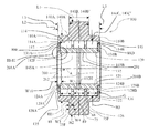
- FIG. 2 is a cross sectional view of the outer ring and inner ring of the yoke roller assembly of FIG. 1 taken across line II-II of FIG. 1 ;
- FIG. 3 is an enlarged view of detail III-III of FIG. 2 .
- a yoke roller assembly for various industrial and commercial applications including but not limited to use in beverage can body forming machines is generally indicated by the numeral 100 .
- the yoke roller assembly 100 includes a bearing having an outer ring 110 and an inner ring 120 extending through the outer ring 110 (as described further below).
- the outer ring 110 is adapted to rotate relative to the inner ring 120 .
- the yoke roller assembly 100 is adapted for installation in an assembled state to preclude the need for assembling components of the yoke roller assembly in the field, for example, during maintenance outages of the beverage can body forming machine.
- the yoke roller assembly 100 is adapted for installation in a beverage can forming machine, in a pre-assembled state.
- the inner ring 120 and the outer ring 110 are manufactured from a metallic material such as a steel alloy or stainless steel alloy.
- the outer ring 110 has an interior area 112 defined by an inner surface 112 F extending between a first axial end 110 A and a second axial end 110 B of the outer ring 110 .
- the inner surface 112 F has a radially inward facing bearing surface 114 extending between a first radially inwardly extending flange 114 A and a second radially inwardly extending flange 114 B.
- the inner ring 120 extends through the interior area 112 of the outer ring 110 .
- the inner ring 120 has an outer surface 122 that extends between a third axial end 124 A of the inner ring 120 and a fourth axial end 124 B of the inner ring.
- the outer surface 122 has a first axially outwardly extending shoulder 128 A proximate the third axial end 124 A and a second axially outwardly extending shoulder 128 B proximate the fourth axial end 124 B.
- a radially outwardly facing bearing surface 126 extends between the first axially outwardly extending shoulder 128 A and the second axially outwardly extending shoulder 128 B.
- a first radially outwardly facing seating surface 129 A extends along the outer surface 122 from the first axially outwardly extending shoulder 128 A axially outwardly to the third axial end 124 A; and a second radially outwardly facing seating surface 129 B extends along the outer surface 122 from the second axially outwardly extending shoulder 128 B axially outward to the fourth axial end 124 B.
- a first end plate 131 A (e.g., an annular ring or washer made of a metallic material such as a steel alloy or stainless steel alloy) is positioned at (e.g., an axially inward surface 135 F (see FIG. 3 ) of the first end plate abutting) the first axially outwardly extending shoulder 128 A and a radially inward facing surface 133 (see FIG. 3 ) of the first end plate 131 A engages the first radially outwardly facing seating surface 129 A.
- a first end plate 131 A e.g., an annular ring or washer made of a metallic material such as a steel alloy or stainless steel alloy
- a second end plate 131 B (e.g., an annular ring or washer made of a metallic material such as a steel alloy or stainless steel alloy) is positioned at (e.g., an axially inward surface 135 F of the second end plate abutting abutting) the second axially outwardly extending shoulder 128 B and a radially inward facing surface 133 of the second end plate 131 B engages the second radially outwardly facing seating surface 129 B.
- the first end plate 131 A is press fit (i.e., interference fit) onto the first radially outwardly facing seating surface 129 A.
- the second end plate 131 B is press fit (i.e., interference fit) onto the second radially outwardly facing seating surface 129 B.
- the end plates 131 A and/or 131 B are swaged into the inner ring 120 by swaging tapered surfaces 202 on a radially inner circumferential surface of the respective shoulder 128 A and 128 B, radially outward, as described further herein with reference to FIGS. 2 and 3 .
- the first and second end plates 131 A and 131 B have a radially outward facing circumferential surface 136 that is spaced apart from a radially inward facing circumferential surface 135 of the respective flange 114 A and 114 B by a gap G to facilitate rotation of the outer ring 110 relative to the inner ring 120 .
- the inner ring 120 has a groove 132 formed therein.
- the groove 132 facilitates lubrication of components that are regularly in dynamic contact during use (e.g., the inner ring, the outer ring, etc.).
- the groove 132 communicates with one or more lubricant pathways 132 H (for example, two lubricant pathways 132 H are shown in FIG. 2 ), which further facilitate lubrication of contacting components of the yoke roller assembly 100 .
- the yoke roller assembly 100 further includes a first row 140 A of a plurality of first rollers 140 A′, a second row 140 B of a plurality of second rollers 140 B′, and a third row 140 C of a plurality of third rollers 140 C′.
- Each of the first rollers 140 A′ in the first row 140 A, each of the second rollers 140 B′ in the second row 140 B, and each of the third rollers 140 C′ in the third row are positioned in the interior area 112 , and are—individually and collectively—positioned between; and in rolling engagement with: (1) the radially outwardly facing bearing surface 126 ; and (2) the radially inward facing bearing surface 114 .
- the plurality of first rollers 140 A′, the plurality of second rollers 140 B′, and/or the plurality of third rollers 140 C′ are manufactured from a metallic material such as a steel alloy or stainless steel alloy.
- An axial end 88 E of each of the first rollers 140 A′ of the first row 140 A engages (e.g., slidingly engages) an axially inward facing side surface of the first radially extending flange 114 A.
- Each of the second rollers 140 B′ of the second row 140 B is positioned between the first row 140 A and the third row 140 C.
- An axial end 88 D of each of the third rollers 140 C′ of the third row 140 C engages (e.g., slidingly engages) an axially inward facing side surface of the second radially extending flange 114 B.
- each of the first rollers 140 A′ of the first row 140 A engages (e.g., slidingly engages) an axially inward facing side surface of the first end plate 131 A.
- the axial end 88 D of each of the third rollers 140 C′ of the third row 140 C engages (e.g., slidingly engages) an axially inward facing side surface of the second end plate 131 B.
- the first radially extending flange 114 A; the second radially extending flange 114 B; the first end plate 131 A and/or the second end plate 131 B cooperate with one another to axially retain and limit axial movement of the first rollers 140 A′, the second rollers 140 B′ and the third rollers 140 C′.
- a spacer 145 A is positioned between the first row 140 A and the second row 140 B.
- Each of the first rollers 140 A′ and the second rollers 140 B′ engage (e.g., slidingly engages) the spacer 145 A.
- the present invention is not limited in this regard, however, as additional spacers may be employed.
- an additional spacer could be positioned between the first row 140 A and the first radially inwardly extending flange 114 A.
- a spacer 145 B is positioned between the second row 140 B and the third row 140 C.
- Each of the second rollers 140 B′ and the third rollers 140 C′ engage (e.g., slidingly engages) the spacers 145 B.
- the present invention is not limited in this regard, however, as additional spacers may be employed.
- an additional spacer could be positioned between the third row 140 C and the second radially inwardly extending flange 114 B.
- the term “spacer,” such as the spacer 145 is used in reference to an element adapted to create separation between rollers.
- the spacer 145 A of FIG. 2 is an annular ring adapted to maintain a predetermined distance between the first row 140 A and the second row 140 B; and the spacer 145 B of FIG. 2 is an annular ring adapted to maintain a predetermined distance between the second row 140 B and the third row 140 C.
- the spacers 145 are manufactured from a metallic material, such as a steel alloy or a stainless steel alloy.
- the spacers 145 are manufactured from a plastic material or polymer.
- the inner ring 120 has a bore 200 extending therethrough.
- the bore 200 includes an interior cylindrical surface 201 that extends from an edge of the groove 132 to a first end 201 A and from an opposite edge of the groove 132 to a second end 201 B, thereof.
- Each of the first axially outwardly extending shoulder 128 A and the second axially outwardly extending shoulder 128 B have the tapered surface 202 extending radially and axially outwardly on a radially inward facing surface of the respective shoulder 128 A and 128 B, from the respective one of the first end 201 A and the second end 201 B, in the direction of the arrow Q, as shown in FIG. 3 .
- the tapered surface 202 is adapted to facilitate installation of the yoke roller assembly 100 , e.g., upon a shaft of slightly larger diameter than the bore.
- the tapered surface 202 is defined by an angle ⁇ (see FIG. 3 ) measured relative to a line parallel to a longitudinal axis A of the yoke roller assembly 100 .
- the angle ⁇ is between 5 and 20 degrees.
- the tapered surface 202 extends an axial distance W 10 .
- the tapered surfaces 202 are adapted to facilitate swaging of the end plates 131 A and 131 B into the inner ring 120 , for example, by creating an area of reduced cross section on the tapered surfaces 202 that are swaged radially outward to fixedly secure the end plates 131 A and 131 B in position in the inner ring 120 .
- the swaging of the tapered surfaces 202 radially outward causes the respective first and second radially outwardly facing seating surfaces 129 A and 129 B to fixedly engage the respective end plate 131 A and 131 B, for example at a radially inner portion of the end plates 131 A and 131 B.
- the yoke roller assembly 100 is adapted for installation in an assembled state. In one embodiment, the yoke roller assembly 100 is adapted for use in a beverage can forming machine.
- the outer ring 110 of the yoke roller assembly 100 has an axial width L 2 that extends between the first end 110 A and the second end 110 B.
- the outer ring 110 has an outside diameter H 1 proximate each of the first end 110 A and the second end 110 B.
- the outer ring 110 has an inside diameter H 3 measured across the radially inward facing bearing surface 114 .
- the outer ring 110 has a radially outwardly extending lobe 75 circumferentially extending around the outer ring 110 .
- the lobe 75 is positioned between (e.g., centered) the first end 110 A and the second end 110 B of the outer ring 110 .
- the lobe 75 has an outside diameter H 2 and an axial width L 1 .
- the width L 1 of the lobe 75 is less than the width L 2 of the outer ring 110 .
- the ratio of the width L 1 to the width L 2 is between 0.4 and 0.5.
- the outside diameter H 1 is of the outer ring 110 is less than the outside diameter L 2 of the lobe 75 .
- the ratio of the outside diameter H 1 to the outside diameter H 2 is between 0.6 and 0.8.
- the ratio of the inside diameter H 3 to the outside diameter H 1 is from 0.7 to 0.9.
- the ratio of the inside diameter H 3 to the outside diameter H 1 is from 0.8 to 0.85.
- the ratio of the inside diameter H 3 to the outside diameter H 1 is configured to reduce the mass of outer ring 110 and thus the inertial effects due to rapid acceleration when the outer ring 110 engages the cam during operation. This ratio compares to prior art bearings having a ratio of the inside diameter H 3 to the outside diameter H 1 of less than 70 percent.
- the first rollers 140 A′, the second rollers 140 B′ and the third rollers 140 C′ have an axial width W.
- the first rollers 140 A′ and the third rollers 140 C′ have inboard axial end faces 88 and the second rollers 140 B′ have opposing axial end faces 89 .
- the lobe 75 has opposing axial end faces 75 F.
- One of the axial faces 75 F is spaced apart from the first axial end 110 A of the outer ring 110 by a distance L 3 .
- the opposing axial face 75 F is spaced apart from the second axial end 110 B by a distance L 3 .
- the distance L 3 is equal to the width L 2 of the outer ring 110 minus the width W 1 of the lobe 75 , divided by two.
- the width W 10 of the tapered surface 202 is from 10 to 35 percent of the distance L 3 . In one embodiment, the width W 10 of the tapered surface 202 is between 5 and 20 percent of the distance L 3 .
- the second rollers 140 B′ are positioned axially between the inner ring 120 and the outer ring 110 such that the opposing axial ends 89 of the second rollers 140 B′ are axially inward from the respective axial end faces 75 F of the lobe 75 , (e.g., the axial end 89 of the second rollers 140 B′ are spaced apart from the axial end faces 75 F of the lobe 75 by a distance W 4 ).
- the axial end faces 88 of the first rollers 140 A′ and the third rollers 140 C′ are positioned axially inward of the respective axial end faces 75 F of the lobe 75 (e.g., the axial ends 88 of the first rollers 140 A′ and the third rollers 140 C′ are spaced apart from the axial end faces 75 F of the lobe 75 by a distance W 3 ).
- the distances W 3 and W 4 are predetermined and selected to minimize flexure of the outer ring 110 under loaded conditions.
- the yoke roller assembly 100 of the present invention has an operating life with insignificant wear of at least four times that of a comparable prior art bearing having only two rows of rollers, as verified via field testing in an actual production environment.
Abstract
Description
Claims (16)
Priority Applications (1)
| Application Number | Priority Date | Filing Date | Title |
|---|---|---|---|
| US15/416,173 US10167896B2 (en) | 2016-01-26 | 2017-01-26 | Triple row yoke roller assembly |
Applications Claiming Priority (2)
| Application Number | Priority Date | Filing Date | Title |
|---|---|---|---|
| US201662287189P | 2016-01-26 | 2016-01-26 | |
| US15/416,173 US10167896B2 (en) | 2016-01-26 | 2017-01-26 | Triple row yoke roller assembly |
Publications (2)
| Publication Number | Publication Date |
|---|---|
| US20170211619A1 US20170211619A1 (en) | 2017-07-27 |
| US10167896B2 true US10167896B2 (en) | 2019-01-01 |
Family
ID=59360305
Family Applications (1)
| Application Number | Title | Priority Date | Filing Date |
|---|---|---|---|
| US15/416,173 Active 2037-02-09 US10167896B2 (en) | 2016-01-26 | 2017-01-26 | Triple row yoke roller assembly |
Country Status (1)
| Country | Link |
|---|---|
| US (1) | US10167896B2 (en) |
Cited By (1)
| Publication number | Priority date | Publication date | Assignee | Title |
|---|---|---|---|---|
| US11335523B2 (en) | 2019-06-04 | 2022-05-17 | Hubbell Incorporated | Support for electrical switch |
Citations (14)
| Publication number | Priority date | Publication date | Assignee | Title |
|---|---|---|---|---|
| US2029265A (en) | 1934-05-30 | 1936-01-28 | Skf Svenska Kullagerfab Ab | Multirow cylindrical roller bearing |
| US3302987A (en) | 1960-01-04 | 1967-02-07 | Ind Schaeffer Ohg | Multi-row cylindrical roller bearings |
| US4270815A (en) * | 1978-07-13 | 1981-06-02 | Skf Kugellagerfabriken Gmbh | Roller bearing |
| US4298331A (en) | 1979-11-09 | 1981-11-03 | Owens-Illinois, Inc. | Container fabricating machine |
| US4398776A (en) * | 1980-11-24 | 1983-08-16 | Fag Kugelfischer Georg Schafer & Co. | Roller bearing with annular retaining disks |
| US4605390A (en) | 1983-09-13 | 1986-08-12 | Japan Tobacco Inc. | Packing container forming apparatus |
| US5517957A (en) * | 1994-10-22 | 1996-05-21 | Ina Walzlager Schaeffler Kg | Device for damping torsional vibrations in a drive train |
| US5531137A (en) | 1988-07-12 | 1996-07-02 | Roller Bearing Company Of America | Cam follower assembly |
| US7841222B2 (en) | 2003-08-28 | 2010-11-30 | Dayton Systems Group, Inc. | Container end forming system |
| WO2014188900A1 (en) | 2013-05-20 | 2014-11-27 | Thk株式会社 | Double-row roller bearing |
| WO2015003696A1 (en) | 2013-07-08 | 2015-01-15 | Schaeffler Technologies Gmbh & Co. Kg | Support bearing, in particular running roller |
| WO2015176700A1 (en) | 2014-05-19 | 2015-11-26 | KaLoTec GmbH | Roller cutter and tunnelling machine |
| US20160061257A1 (en) | 2012-01-24 | 2016-03-03 | Us Synthetic Corporation | Roller bearing assemblies and apparatuses |
| US20160195136A1 (en) | 2013-09-18 | 2016-07-07 | Ntn Corporation | Bearing structure |
-
2017
- 2017-01-26 US US15/416,173 patent/US10167896B2/en active Active
Patent Citations (14)
| Publication number | Priority date | Publication date | Assignee | Title |
|---|---|---|---|---|
| US2029265A (en) | 1934-05-30 | 1936-01-28 | Skf Svenska Kullagerfab Ab | Multirow cylindrical roller bearing |
| US3302987A (en) | 1960-01-04 | 1967-02-07 | Ind Schaeffer Ohg | Multi-row cylindrical roller bearings |
| US4270815A (en) * | 1978-07-13 | 1981-06-02 | Skf Kugellagerfabriken Gmbh | Roller bearing |
| US4298331A (en) | 1979-11-09 | 1981-11-03 | Owens-Illinois, Inc. | Container fabricating machine |
| US4398776A (en) * | 1980-11-24 | 1983-08-16 | Fag Kugelfischer Georg Schafer & Co. | Roller bearing with annular retaining disks |
| US4605390A (en) | 1983-09-13 | 1986-08-12 | Japan Tobacco Inc. | Packing container forming apparatus |
| US5531137A (en) | 1988-07-12 | 1996-07-02 | Roller Bearing Company Of America | Cam follower assembly |
| US5517957A (en) * | 1994-10-22 | 1996-05-21 | Ina Walzlager Schaeffler Kg | Device for damping torsional vibrations in a drive train |
| US7841222B2 (en) | 2003-08-28 | 2010-11-30 | Dayton Systems Group, Inc. | Container end forming system |
| US20160061257A1 (en) | 2012-01-24 | 2016-03-03 | Us Synthetic Corporation | Roller bearing assemblies and apparatuses |
| WO2014188900A1 (en) | 2013-05-20 | 2014-11-27 | Thk株式会社 | Double-row roller bearing |
| WO2015003696A1 (en) | 2013-07-08 | 2015-01-15 | Schaeffler Technologies Gmbh & Co. Kg | Support bearing, in particular running roller |
| US20160195136A1 (en) | 2013-09-18 | 2016-07-07 | Ntn Corporation | Bearing structure |
| WO2015176700A1 (en) | 2014-05-19 | 2015-11-26 | KaLoTec GmbH | Roller cutter and tunnelling machine |
Cited By (1)
| Publication number | Priority date | Publication date | Assignee | Title |
|---|---|---|---|---|
| US11335523B2 (en) | 2019-06-04 | 2022-05-17 | Hubbell Incorporated | Support for electrical switch |
Also Published As
| Publication number | Publication date |
|---|---|
| US20170211619A1 (en) | 2017-07-27 |
Similar Documents
| Publication | Publication Date | Title |
|---|---|---|
| CN101418831B (en) | Seal for railway car journal bearing | |
| CN102190003B (en) | Railway car bearing seal | |
| CN110645338B (en) | Pulley device for a tension roller or a winding roller | |
| US11162571B2 (en) | Pulley device, in particular for tensioning idler or runner roller | |
| US11306808B2 (en) | Pulley device, in particular for tensioning idler or runner roller | |
| US10655672B2 (en) | Method and device for producing an angular contact roller bearing | |
| US20110116734A1 (en) | Punched retainer, self-aligning roller bearing, and method of manufacturing punched retainer | |
| US20080226214A1 (en) | Roller Bearing | |
| US10697493B2 (en) | Cam follower with multiple rows of independently operating bearings | |
| WO2013021887A1 (en) | Tapered roller bearing and mounting structure therefor | |
| CN111550535A (en) | Pulley device, in particular for tensioning an idler or moving roller | |
| EP2085666B1 (en) | Sealing device and rolling bearing device | |
| US20140248016A1 (en) | Composite annular seal assembly for bearings | |
| US10167896B2 (en) | Triple row yoke roller assembly | |
| US11220279B2 (en) | Insert and wear ring for a railway roller bearing | |
| US20190277388A1 (en) | Pulley device for tensioner or winder roller | |
| US9551376B2 (en) | Bearing configuration with two-row polygonal bearing | |
| US10570960B2 (en) | Segmented cage for rolling bearing | |
| US10753402B2 (en) | Bearing assembly and bearing cage | |
| CN110230674B (en) | Pulley device for a tension roller or a winding roller | |
| JP2018059563A (en) | Cam Follower | |
| JP2014190352A (en) | Taper roller bearing | |
| WO2018101038A1 (en) | Roller bearing | |
| JP2010116107A (en) | Axle device for railway vehicle | |
| US9328767B2 (en) | Bearing assembly |
Legal Events
| Date | Code | Title | Description |
|---|---|---|---|
| AS | Assignment |
Owner name: ROLLER BEARING COMPANY OF AMERICA, INC., CONNECTIC Free format text: ASSIGNMENT OF ASSIGNORS INTEREST;ASSIGNORS:MALYCHOK, ROMAN;MALYCHOK, LUDA;SMITH, BRADLEY T.;SIGNING DATES FROM 20170223 TO 20170301;REEL/FRAME:043065/0409 |
|
| STCF | Information on status: patent grant |
Free format text: PATENTED CASE |
|
| AS | Assignment |
Owner name: WELLS FARGO BANK, NATIONAL ASSOCIATION, AS COLLATE Free format text: SECURITY AGREEMENT;ASSIGNOR:ROLLER BEARING COMPANY OF AMERICA, INC.;REEL/FRAME:048208/0456 Effective date: 20190131 Owner name: WELLS FARGO BANK, NATIONAL ASSOCIATION, AS COLLATERAL AGENT, NORTH CAROLINA Free format text: SECURITY AGREEMENT;ASSIGNOR:ROLLER BEARING COMPANY OF AMERICA, INC.;REEL/FRAME:048208/0456 Effective date: 20190131 |
|
| AS | Assignment |
Owner name: SARGENT AEROSPACE & DEFENSE, LLC, ARIZONA Free format text: RELEASE BY SECURED PARTY;ASSIGNOR:WELLS FARGO BANK, NATIONAL ASSOCIATION;REEL/FRAME:057988/0608 Effective date: 20211101 Owner name: ROLLER BEARING COMPANY OF AMERICA, INC., CONNECTICUT Free format text: RELEASE BY SECURED PARTY;ASSIGNOR:WELLS FARGO BANK, NATIONAL ASSOCIATION;REEL/FRAME:057988/0608 Effective date: 20211101 Owner name: RBC SOUTHWEST PRODUCTS, INC., CONNECTICUT Free format text: RELEASE BY SECURED PARTY;ASSIGNOR:WELLS FARGO BANK, NATIONAL ASSOCIATION;REEL/FRAME:057988/0608 Effective date: 20211101 Owner name: RBC BEARINGS INCORPORATED, CONNECTICUT Free format text: RELEASE BY SECURED PARTY;ASSIGNOR:WELLS FARGO BANK, NATIONAL ASSOCIATION;REEL/FRAME:057988/0608 Effective date: 20211101 |
|
| AS | Assignment |
Owner name: WELLS FARGO BANK, NATIONAL ASSOCIATION, AS COLLATERAL AGENT, COLORADO Free format text: SECURITY INTEREST;ASSIGNOR:ROLLER BEARING COMPANY OF AMERICA, INC.;REEL/FRAME:058099/0259 Effective date: 20211101 |
|
| MAFP | Maintenance fee payment |
Free format text: PAYMENT OF MAINTENANCE FEE, 4TH YEAR, LARGE ENTITY (ORIGINAL EVENT CODE: M1551); ENTITY STATUS OF PATENT OWNER: LARGE ENTITY Year of fee payment: 4 |