US10167207B2 - Electrolytic apparatus with circulator, reverse osmosis filter, and cooler, for producing reducing water - Google Patents
Electrolytic apparatus with circulator, reverse osmosis filter, and cooler, for producing reducing water Download PDFInfo
- Publication number
- US10167207B2 US10167207B2 US13/627,440 US201213627440A US10167207B2 US 10167207 B2 US10167207 B2 US 10167207B2 US 201213627440 A US201213627440 A US 201213627440A US 10167207 B2 US10167207 B2 US 10167207B2
- Authority
- US
- United States
- Prior art keywords
- water
- cation exchange
- exchange resin
- chamber
- cathode
- Prior art date
- Legal status (The legal status is an assumption and is not a legal conclusion. Google has not performed a legal analysis and makes no representation as to the accuracy of the status listed.)
- Expired - Fee Related, expires
Links
Images


Classifications
-
- C—CHEMISTRY; METALLURGY
- C02—TREATMENT OF WATER, WASTE WATER, SEWAGE, OR SLUDGE
- C02F—TREATMENT OF WATER, WASTE WATER, SEWAGE, OR SLUDGE
- C02F1/00—Treatment of water, waste water, or sewage
- C02F1/46—Treatment of water, waste water, or sewage by electrochemical methods
- C02F1/461—Treatment of water, waste water, or sewage by electrochemical methods by electrolysis
- C02F1/46104—Devices therefor; Their operating or servicing
- C02F1/4618—Devices therefor; Their operating or servicing for producing "ionised" acidic or basic water
-
- B—PERFORMING OPERATIONS; TRANSPORTING
- B01—PHYSICAL OR CHEMICAL PROCESSES OR APPARATUS IN GENERAL
- B01D—SEPARATION
- B01D61/00—Processes of separation using semi-permeable membranes, e.g. dialysis, osmosis or ultrafiltration; Apparatus, accessories or auxiliary operations specially adapted therefor
- B01D61/42—Electrodialysis; Electro-osmosis ; Electro-ultrafiltration; Membrane capacitive deionization
- B01D61/44—Ion-selective electrodialysis
- B01D61/46—Apparatus therefor
- B01D61/48—Apparatus therefor having one or more compartments filled with ion-exchange material, e.g. electrodeionisation
-
- B—PERFORMING OPERATIONS; TRANSPORTING
- B01—PHYSICAL OR CHEMICAL PROCESSES OR APPARATUS IN GENERAL
- B01D—SEPARATION
- B01D61/00—Processes of separation using semi-permeable membranes, e.g. dialysis, osmosis or ultrafiltration; Apparatus, accessories or auxiliary operations specially adapted therefor
- B01D61/42—Electrodialysis; Electro-osmosis ; Electro-ultrafiltration; Membrane capacitive deionization
- B01D61/44—Ion-selective electrodialysis
- B01D61/54—Controlling or regulating
-
- B—PERFORMING OPERATIONS; TRANSPORTING
- B01—PHYSICAL OR CHEMICAL PROCESSES OR APPARATUS IN GENERAL
- B01D—SEPARATION
- B01D61/00—Processes of separation using semi-permeable membranes, e.g. dialysis, osmosis or ultrafiltration; Apparatus, accessories or auxiliary operations specially adapted therefor
- B01D61/58—Multistep processes
-
- B—PERFORMING OPERATIONS; TRANSPORTING
- B01—PHYSICAL OR CHEMICAL PROCESSES OR APPARATUS IN GENERAL
- B01D—SEPARATION
- B01D61/00—Processes of separation using semi-permeable membranes, e.g. dialysis, osmosis or ultrafiltration; Apparatus, accessories or auxiliary operations specially adapted therefor
- B01D61/02—Reverse osmosis; Hyperfiltration ; Nanofiltration
- B01D61/025—Reverse osmosis; Hyperfiltration
-
- C—CHEMISTRY; METALLURGY
- C02—TREATMENT OF WATER, WASTE WATER, SEWAGE, OR SLUDGE
- C02F—TREATMENT OF WATER, WASTE WATER, SEWAGE, OR SLUDGE
- C02F1/00—Treatment of water, waste water, or sewage
- C02F1/44—Treatment of water, waste water, or sewage by dialysis, osmosis or reverse osmosis
- C02F1/441—Treatment of water, waste water, or sewage by dialysis, osmosis or reverse osmosis by reverse osmosis
-
- C—CHEMISTRY; METALLURGY
- C02—TREATMENT OF WATER, WASTE WATER, SEWAGE, OR SLUDGE
- C02F—TREATMENT OF WATER, WASTE WATER, SEWAGE, OR SLUDGE
- C02F1/00—Treatment of water, waste water, or sewage
- C02F1/42—Treatment of water, waste water, or sewage by ion-exchange
- C02F2001/425—Treatment of water, waste water, or sewage by ion-exchange using cation exchangers
-
- C—CHEMISTRY; METALLURGY
- C02—TREATMENT OF WATER, WASTE WATER, SEWAGE, OR SLUDGE
- C02F—TREATMENT OF WATER, WASTE WATER, SEWAGE, OR SLUDGE
- C02F1/00—Treatment of water, waste water, or sewage
- C02F1/46—Treatment of water, waste water, or sewage by electrochemical methods
- C02F1/461—Treatment of water, waste water, or sewage by electrochemical methods by electrolysis
- C02F1/46104—Devices therefor; Their operating or servicing
- C02F1/46109—Electrodes
- C02F2001/46152—Electrodes characterised by the shape or form
- C02F2001/46157—Perforated or foraminous electrodes
-
- C—CHEMISTRY; METALLURGY
- C02—TREATMENT OF WATER, WASTE WATER, SEWAGE, OR SLUDGE
- C02F—TREATMENT OF WATER, WASTE WATER, SEWAGE, OR SLUDGE
- C02F1/00—Treatment of water, waste water, or sewage
- C02F1/46—Treatment of water, waste water, or sewage by electrochemical methods
- C02F1/461—Treatment of water, waste water, or sewage by electrochemical methods by electrolysis
- C02F1/46104—Devices therefor; Their operating or servicing
- C02F1/4618—Devices therefor; Their operating or servicing for producing "ionised" acidic or basic water
- C02F2001/4619—Devices therefor; Their operating or servicing for producing "ionised" acidic or basic water only cathodic or alkaline water, e.g. for reducing
-
- C—CHEMISTRY; METALLURGY
- C02—TREATMENT OF WATER, WASTE WATER, SEWAGE, OR SLUDGE
- C02F—TREATMENT OF WATER, WASTE WATER, SEWAGE, OR SLUDGE
- C02F1/00—Treatment of water, waste water, or sewage
- C02F1/46—Treatment of water, waste water, or sewage by electrochemical methods
- C02F1/461—Treatment of water, waste water, or sewage by electrochemical methods by electrolysis
- C02F1/46104—Devices therefor; Their operating or servicing
- C02F1/4618—Devices therefor; Their operating or servicing for producing "ionised" acidic or basic water
- C02F2001/46195—Devices therefor; Their operating or servicing for producing "ionised" acidic or basic water characterised by the oxidation reduction potential [ORP]
-
- C—CHEMISTRY; METALLURGY
- C02—TREATMENT OF WATER, WASTE WATER, SEWAGE, OR SLUDGE
- C02F—TREATMENT OF WATER, WASTE WATER, SEWAGE, OR SLUDGE
- C02F2103/00—Nature of the water, waste water, sewage or sludge to be treated
- C02F2103/02—Non-contaminated water, e.g. for industrial water supply
- C02F2103/026—Treating water for medical or cosmetic purposes
-
- C—CHEMISTRY; METALLURGY
- C02—TREATMENT OF WATER, WASTE WATER, SEWAGE, OR SLUDGE
- C02F—TREATMENT OF WATER, WASTE WATER, SEWAGE, OR SLUDGE
- C02F2201/00—Apparatus for treatment of water, waste water or sewage
- C02F2201/46—Apparatus for electrochemical processes
- C02F2201/461—Electrolysis apparatus
- C02F2201/46105—Details relating to the electrolytic devices
- C02F2201/46115—Electrolytic cell with membranes or diaphragms
-
- C—CHEMISTRY; METALLURGY
- C02—TREATMENT OF WATER, WASTE WATER, SEWAGE, OR SLUDGE
- C02F—TREATMENT OF WATER, WASTE WATER, SEWAGE, OR SLUDGE
- C02F2201/00—Apparatus for treatment of water, waste water or sewage
- C02F2201/46—Apparatus for electrochemical processes
- C02F2201/461—Electrolysis apparatus
- C02F2201/46105—Details relating to the electrolytic devices
- C02F2201/46155—Heating or cooling
-
- C—CHEMISTRY; METALLURGY
- C02—TREATMENT OF WATER, WASTE WATER, SEWAGE, OR SLUDGE
- C02F—TREATMENT OF WATER, WASTE WATER, SEWAGE, OR SLUDGE
- C02F2201/00—Apparatus for treatment of water, waste water or sewage
- C02F2201/46—Apparatus for electrochemical processes
- C02F2201/461—Electrolysis apparatus
- C02F2201/46105—Details relating to the electrolytic devices
- C02F2201/4618—Supplying or removing reactants or electrolyte
-
- C—CHEMISTRY; METALLURGY
- C02—TREATMENT OF WATER, WASTE WATER, SEWAGE, OR SLUDGE
- C02F—TREATMENT OF WATER, WASTE WATER, SEWAGE, OR SLUDGE
- C02F2209/00—Controlling or monitoring parameters in water treatment
- C02F2209/42—Liquid level
-
- C—CHEMISTRY; METALLURGY
- C02—TREATMENT OF WATER, WASTE WATER, SEWAGE, OR SLUDGE
- C02F—TREATMENT OF WATER, WASTE WATER, SEWAGE, OR SLUDGE
- C02F2301/00—General aspects of water treatment
- C02F2301/04—Flow arrangements
- C02F2301/046—Recirculation with an external loop
-
- C—CHEMISTRY; METALLURGY
- C02—TREATMENT OF WATER, WASTE WATER, SEWAGE, OR SLUDGE
- C02F—TREATMENT OF WATER, WASTE WATER, SEWAGE, OR SLUDGE
- C02F2307/00—Location of water treatment or water treatment device
- C02F2307/12—Location of water treatment or water treatment device as part of household appliances such as dishwashers, laundry washing machines or vacuum cleaners
-
- Y—GENERAL TAGGING OF NEW TECHNOLOGICAL DEVELOPMENTS; GENERAL TAGGING OF CROSS-SECTIONAL TECHNOLOGIES SPANNING OVER SEVERAL SECTIONS OF THE IPC; TECHNICAL SUBJECTS COVERED BY FORMER USPC CROSS-REFERENCE ART COLLECTIONS [XRACs] AND DIGESTS
- Y02—TECHNOLOGIES OR APPLICATIONS FOR MITIGATION OR ADAPTATION AGAINST CLIMATE CHANGE
- Y02T—CLIMATE CHANGE MITIGATION TECHNOLOGIES RELATED TO TRANSPORTATION
- Y02T10/00—Road transport of goods or passengers
- Y02T10/10—Internal combustion engine [ICE] based vehicles
- Y02T10/12—Improving ICE efficiencies
Definitions
- Embodiments of the present disclosure relate to an apparatus for producing reducing water. More specifically, embodiments of the present disclosure relate to an apparatus for producing reducing water with superior reducing force.
- water is obtained by a variety of methods.
- a water purifier is used, including a household alkali ion water purifier which is used in order to promote healthful attributes of water to reduce un-wellness or ill health of the body.
- On type of water purifier is a reverse osmosis (RO) type water purifier which is capable of removing 70 to 90% of turbidity, bacteria, viruses, organic compounds, agricultural chemicals, heavy metals, disinfection by-products, inorganic ions and the like present in water and obtaining clean and drinkable water having a neutral range of pH (pH of 5.8 to 8.5).
- RO reverse osmosis
- such a water purifier has a configuration in which 3 to 5 filters are commonly mounted in a water purifier, purified water is stored in a water tank, and either cool water or hot water is selectively obtained, as desired.
- water obtained from a water purifier has only a basic function of satisfying thirst of human body to support life, and has an oxidization force equivalent to or higher than tap water in terms of the health index represented by an oxidation reduction potential (hereinafter, referred to as an “ORP”) of water.
- ORP oxidation reduction potential
- alkali ion water purifier is a medical apparatus for producing pH 8.5 or higher water, which provides reduction effects in four gastrointestinal symptoms (chronic diarrhea, dyspepsia, gastrointestinal heterofermentation, and hypergastric acidity) and has been approved by the Korean Food and Drug Administration.
- gastrointestinal symptoms chronic diarrhea, dyspepsia, gastrointestinal heterofermentation, and hypergastric acidity
- the alkali ion water purifier is efficacious in treatment of various diseases such as intestinal diseases, vascular diseases, diabetes and atopic dermatitis.
- Recent academy and research paper reports that the main efficacy is caused by the reducing force of water.
- water in the alkali ion water purifier should contain a sufficient amount of ions, since ions dissolved in water serve as electrolytes and alkali ion water is produced during normal electrolysis.
- the filter is limited to an ultra-filtration (UF) filter, satisfying general water purification requirements, rather than an RO filter.
- UF ultra-filtration
- pH of water is increased. The alkali ion water thus produced is unsuitable for use in drinkable water.
- an apparatus for producing reducing water includes an electrolytic bath including a cathode chamber provided with a cathode, an anode chamber provided with an anode, and an intermediate chamber interposed between the cathode chamber and the anode chamber, wherein the cathode chamber and the intermediate chamber are provided with an inlet through which water is supplied, and an outlet through which water is discharged, a cation exchange membrane is provided between the cathode chamber and the intermediate chamber, and the intermediate chamber includes a cation exchange resin that dissociates hydrogen ions when the cation exchange resin reacts with water.
- the apparatus may further include a circulator to supply water to the intermediate chamber and supply water discharged through the cation exchange resin to the intermediate chamber again.
- the circulator may include: a water tank to store water supplied to the intermediate chamber; a channel to form a passage, enabling water present in the water tank to circulate between the intermediate chamber and the water tank; and a pump to circulate water present in the water tank to circulate between the intermediate chamber and the water tank.
- the water tank may include a water level sensor to sense a level of water stored in the water tank.
- the water tank may include an outlet through which water stored in the water tank is discharged outside.
- the apparatus may include a cooling apparatus to reduce temperature of water supplied to the intermediate chamber by the circulator.
- the cooling apparatus may include a fan or a cooler using a thermoelectric semiconductor or a refrigerant.
- the circulator may include a channel to form a passage, enabling water having passed through the intermediate chamber to be introduced into the intermediate chamber again; a pump to circulate water supplied to the intermediate chamber along the channel; and a valve to control flow of water supplied to the intermediate chamber.
- the apparatus may further include a reverse osmosis (RO) filter to purify water supplied to the electrolytic bath or the circulator.
- RO reverse osmosis
- the apparatus may further include a valve to control flow of water so that the water supplied from the RO filter is supplied to the cathode chamber or the circulator.
- the apparatus may further include a cation exchange membrane disposed between the anode chamber and the intermediate chamber.
- the cathode, the cation exchange membrane provided between the cathode chamber and the intermediate chamber, and the cation exchange resin may contact one another, and the cation exchange resin, the cation exchange membrane provided between the intermediate chamber and the anode chamber, and the anode may contact one another.
- the cathode and the anode may be provided with holes through which water is passed.
- the cathode and the anode may have a mesh structure.
- the cation exchange resin may be recycled by reversing the cathode and the anode.
- the apparatus may further include a power supply to supply voltage to the electrolytic bath.
- the apparatus may further include a cation exchange resin filter through which water supplied to the intermediate chamber is passed.
- the cation exchange resin filter may further include a cation exchange resin that dissociates hydrogen ions, when the cation exchange resin reacts with water.
- the apparatus may further include a reverse osmosis (RO) filter to purify water supplied to the cation exchange resin filter or the cathode chamber.
- RO reverse osmosis
- the apparatus may further include a branch channel to supply water purified through the RO filter to the cation exchange resin filter and the cathode chamber of the electrolytic bath.
- the cation exchange resin filter may include an inlet through which water supplied from the RO filter is introduced; and an outlet through which water supplied to the intermediate chamber is discharged.
- the cation exchange resin filter may be interposed between the RO filter and the electrolytic bath such that water passes through the cation exchange resin filter, before the water is supplied to the intermediate chamber.
- the cation exchange resin filter may be detachably mounted on the apparatus for producing reducing water.
- an apparatus for producing reducing water includes an electrolytic bath including a cathode chamber provided with a cathode, an anode chamber provided with an anode, and an intermediate chamber interposed between the cathode chamber and the anode chamber; and a cation exchange resin filter through which water supplied to the intermediate chamber is passed, wherein the cathode chamber and the intermediate chamber are provided with an inlet through which water is supplied, and an outlet through which water is discharged, and a cation exchange membrane is provided between the cathode chamber and the intermediate chamber.
- the apparatus may further include a cation exchange resin filter through which water supplied to the intermediate chamber is passed.
- the cation exchange resin filter may further include a cation exchange resin that dissociates hydrogen ions, when the cation exchange resin reacts with water.
- the apparatus may further include a reverse osmosis (RO) filter to purify water supplied to the cation exchange resin filter or the cathode chamber.
- RO reverse osmosis
- the apparatus may further include a branch channel to supply water purified through the RO filter to the cation exchange resin filter and the cathode chamber of the electrolytic bath.
- the cation exchange resin filter may include an inlet through which water supplied from the RO filter is introduced; and an outlet through which water supplied to the intermediate chamber is discharged.
- the cation exchange resin filter may be interposed between the RO filter and the electrolytic bath such that water passes through the cation exchange resin filter, before the water is supplied to the intermediate chamber.
- the cation exchange resin filter may be detachably mounted on the apparatus for producing reducing water.
- the apparatus may further include a cation exchange membrane disposed between the anode chamber and the intermediate chamber.
- the cathode, the cation exchange membrane provided between the cathode chamber and the intermediate chamber, and the cation exchange resin may contact one another, and the cation exchange resin, the cation exchange membrane provided between the intermediate chamber and the anode chamber, and the anode may contact one another.
- the cathode and the anode may be provided with holes through which water is passed.
- the cathode and the anode may have a mesh structure.
- FIG. 1 is a schematic view illustrating a driving mechanism of a conventional alkali ion water purifier
- FIGS. 2 and 3 are schematic views illustrating a driving mechanism of an apparatus for producing reducing water according to one embodiment of the present disclosure
- FIG. 4 is a view illustrating a cation exchange resin filter in an apparatus for producing reducing water shown in FIGS. 2 and 3 ;
- FIG. 5 is a schematic view illustrating a driving mechanism of an apparatus for producing reducing water according to a modified embodiment of the embodiment shown in FIGS. 2 and 3 ;
- FIGS. 6 a and 6 b are schematic views illustrating a driving mechanism of an apparatus for producing reducing water, according to another embodiment
- FIG. 7 is a view illustrating a function of the cation exchange resin filled in the intermediate chamber of FIG. 6 ;
- FIG. 8 is a graph showing pH and ORP properties of reducing water produced in the cathode chamber, as a result of electrolysis using the conventional alkali ion water purifier and the apparatus for producing reducing water according to the embodiment illustrated in FIG. 2 or FIG. 6 ;
- FIG. 9 is a schematic view illustrating a driving mechanism of an apparatus for producing reducing water including a circulator according to a modified embodiment of the embodiment illustrated in FIG. 6 ;
- FIG. 10 is a schematic view illustrating a driving mechanism of an apparatus for producing reducing water including a cooling apparatus according to the embodiment illustrated in FIG. 6 ;
- FIGS. 11 a and 11 b are graphs showing pH and ORP properties of reducing water produced in the cathode before and after electrode interchange in the apparatus for producing reducing water described in FIGS. 6 a and 6 b;
- FIGS. 12 a and 12 b are views illustrating a shape of the electrode used for the apparatus for producing reducing water.
- FIG. 13 is a view illustrating configurations of a cation exchange resin, a cation exchange membrane and electrodes in the apparatus for producing reducing water according to embodiments of the present disclosure.
- FIG. 1 is a schematic view illustrating a driving mechanism of a conventional alkali ion water purifier.
- the alkali ion water purifier includes a UF filter 11 and an electrolytic bath 12
- the electrolytic bath 12 includes a cathode 13 , an anode 14 and an ion-exchange membrane 16 disposed between the cathode 13 and the anode 14 .
- an electromotive force of a standard hydrogen electrode may be depicted by the following Equation 1 under the assumption that only OH ⁇ and H 2 are abnormally present in water:
- Equation ⁇ ⁇ 1 n represents a number of reacted electrons
- H 2 - standard hydrogen electrode and H 2-cathode represent a H 2 concentration (mol/L) of a standard hydrogen electrode and a H 2 concentration (mol/L) of a cathode, respectively
- OH ⁇ represents a concentration of OH ⁇ (mol/L).
- a hydrogen reduction potential difference is represented by a negative ( ⁇ ) value, since electrons move from a working electrode to the standard hydrogen electrode. In this case, water containing the working electrode represents reducing force.
- the value of hydrogen reduction potential difference is represented by a positive (+) value and a working solution represents an oxidizing force.
- RO filter-type water purifiers have a basic water purification function of removing free residual chlorine, chromaticity, turbidity, chloroform, microorganisms and bacteria present in water, as well as a specific water purification function of removing organic compounds, agricultural chemicals, heavy metals and inorganic ions, to yield pure water free of these components.
- the purified water has an average water conductivity of 5 to 15 ⁇ s/cm, which is 1/15 to 1/40 lower than the average conductivity of general tap water (about 200 to about 220 ⁇ s/cm).
- the apparatus for producing reducing water solves the problems of the water purifier and alkali ion water purifier and thereby enables production of water that exhibits superior reducing force and has a neutral pH range.
- FIGS. 2 and 3 are views illustrating a driving mechanism of an apparatus for producing reducing water according to one embodiment of the present disclosure
- FIG. 4 is a view illustrating a cation exchange resin filter 40 of an apparatus for producing reducing water shown in FIGS. 2 and 3 .
- the apparatus for producing reducing water includes an electrolytic bath 22 including a cathode chamber 41 provided with a cathode 23 , an anode chamber 42 provided with an anode 24 , and an intermediate chamber 43 interposed between the cathode chamber 41 and the anode chamber 42 ; an RO filter 21 to purify water supplied to the electrolytic bath 22 ; and a cation exchange resin filter 40 through which water is supplied to the intermediate chamber 43 of the electrolytic bath 22 .
- the apparatus for producing reducing water adopts only advantages among advantages and disadvantages of a water purifier to provide clean water from which heavy metals, organic substances as well as inorganic ions have been removed, and of an alkali ion water purifier to provide water that has reducibility, but has alkalinity with pH of 8.5 or higher and satisfies a basic purification level from which free residual chlorine, chromaticity, turbidity and chloroform have been removed, thus preparing clean and stable water that exhibits a neutral pH range (pH 5.8 ⁇ 8.5) as well as superior reducing force, and from which microorganisms, bacteria, residual chlorine, heavy metals, organic compounds, agricultural chemicals and the like have been removed.
- a neutral pH range pH 5.8 ⁇ 8.5
- the electrolytic bath 22 includes a cathode chamber 41 provided with a cathode 23 for electrolysis of water, an anode chamber 42 provided with an anode 24 and an intermediate chamber 43 filled with a cation exchange resin 26 , interposed between the cathode chamber 41 and the anode chamber 42 .
- cation exchange membranes 25 and 25 ′ are formed between the cathode 23 and the cation exchange resin 26 , and between the cation exchange resin 26 and the anode 24 , respectively, the cathode 23 , the cation exchange membrane 25 and the cation exchange resin 26 contact one another, and the cation exchange resin 26 , the cation exchange membrane 25 ′ and the anode 24 may also contact one another.
- water passed through the RO filter 21 is added to the electrolytic bath 22 .
- the water passed through the RO filter 21 is directly introduced into the cathode chamber 41 , while the water passed through the RO filter 21 is not directly introduced into the intermediate chamber 43 filled with the cation exchange resin 26 and is introduced into the intermediate chamber 43 after passing through the cation exchange resin filter 40 one more time. Since only cations pass through the cation exchange membranes 25 and 25 ′, water introduced into the cathode chamber 41 is not moved through the cation exchange membrane 25 to the intermediate chamber 43 . Similarly, water introduced into the intermediate chamber 43 is not moved through the cation exchange membrane 25 to the cathode chamber 41 .
- a sediment filter and a carbon filter may be further provided at the front end of the RO filter 21 .
- water has a negative value of ORP in a neutral pH range (5.8 ⁇ 8.5) due to H 2 generated from the cathode 23 , thus exhibiting reducing force.
- water passed through the RO filter 21 is supplied to the cathode chamber 41 of the electrolytic bath 22 , water passed through the cation exchange resin filter 40 is supplied to the intermediate chamber 43 , and water introduced into the cation exchange resin 26 of the intermediate chamber 43 soaks the cation exchange membrane 25 ′ contacting the anode 24 .
- H + produced in the anode 24 is bonded to OH ⁇ produced in the cathode 23 to prevent an increase in pH that is caused by an increase in OH ⁇ , although reducing force of reducing water emitted from the cathode chamber 41 is increased due to increase in H 2 .
- the electrolytic bath 22 may further include a power supply (not shown) to apply a voltage.
- the cation exchange resin 26 filled in the intermediate chamber 43 may be an H + -type cation exchange resin.
- the cation exchange resin 26 is a resin in which a SO 3 H exchange group is linked to the surface of a polymer matrix. In this case, when the resin is soaked in water, H + ions are dissociated from the surface of the resin until they balance with H + ions in water.
- the cation exchange resin 26 is filled in the intermediate chamber 43 made of a “ ⁇ ”-shaped material between the cathode chamber 41 and the anode chamber 42 .
- H + ions generated in the anode 24 cannot be moved to the cathode 23 , while transfer of H + ions is possible from the anode 24 to the cathode 23 based on H+ ions dissociated from the cation exchange resin 26 . Accordingly, a closed-loop configuration in which current flows even at a low voltage within a lifespan limit of the cation exchange resin 26 is formed.
- bacteria are not observed in water passed through the RO filter. However, bacteria may be proliferated due to various causes such as introduction of external matters, as time passes, since the inside of the RO filter is always soaked in water.
- Bacteria adsorbed on the cation exchange resin 26 are not readily detached from the cation exchange resin 26 , and the amount thereof is increased due to proliferation of bacteria, as time passes. As a result, the cation exchange resin 26 is discolored.
- the apparatus for producing reducing water includes a cation exchange resin filter 40 mounted between the RO filter 21 and the intermediate chamber 43 .
- the cation exchange resin filter 40 receives water filtered through the RO filter 21 and supplies the filtered water to the intermediate chamber 43 .
- the cation exchange resin filter 40 includes a housing 48 provided with an empty area in which the cation exchange resin 49 is filled.
- the housing 48 is provided at both ends thereof with an inlet 46 through which water passed through the RO filter 21 is supplied, and an outlet 47 through which the water supplied to the intermediate chamber 43 is discharged.
- the cation exchange resin 49 filled in the empty area is an H + -type cation exchange resin, which is the same type as the cation exchange resin 26 filled in the intermediate chamber 43 of the electrolytic bath 22 .
- H + ions are dissociated from the surface of the resin until they balance with H + ions in water.
- Water added to the cation exchange resin filter 40 is water purified through the RO filter 21 and has a pH of 6.2 to 6.5.
- Water passed through the cation exchange resin filter 40 contains H + ions dissociated from the surface of the cation exchange resin 49 and thus has a decreased pH of 4.2 to 4.5.
- Water passed through the RO filter 21 is separately supplied into the cation exchange resin filter 40 and the cathode chamber 41 of the electrolytic bath 22 through a branch channel 44 .
- the branch channel 44 connected to the cation exchange resin filter 40 is connected to the inlet 46 of the cation exchange resin filter 40 .
- Water passed through the cation exchange resin filter 40 is connected to the intermediate chamber 43 through a channel connected to the cathode chamber 41 and another channel 45 .
- the cation exchange resin filter 40 is detachably mounted on the apparatus for producing reducing water.
- the cation exchange resin 26 is recycled using H + ions generated by electrolysis, thereby extending lifespan of the cation exchange resin 26 .
- H + ions generated by electrolysis in the anode 24 are moved to the cation exchange membrane 25 ′ and the cation exchange resin 26 , and a part of the cation exchange resin 26 adjacent to the anode 24 and the cation exchange membrane 25 ′ is a H+ concentration higher than an equilibrium state and is thus partially recycled.
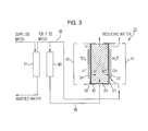
- FIG. 3 when, after electrolysis of a predetermined flow, polarity of the anode 24 and the cathode 23 of the electrolytic bath 22 of FIG. 2 that are bilaterally symmetric and water introduced into the electrolytic bath 22 are alternately changed, the cation exchange resin 26 functions to transfer H+ ions as a catalyst and recycle the same, thus continuously producing reducing water. Also, since water flows only in one direction, contamination of the ion exchange membrane is prevented by reversing flow of water that may be generated.
- the cathode 23 in FIG. 2 is changed into the anode 24 of FIG. 3 and the anode 24 of FIG. 2 is changed into the cathode 23 of FIG. 3 .
- water passed through the RO filter 21 is supplied to the changed cathode chamber 41 disposed at the right. Since this structure is bilaterally symmetric based on the intermediate chamber 43 , depending on the polarity of electrodes, the cathode 23 and the anode 24 may be interchanged.
- FIG. 5 is a view illustrating a driving mechanism of an apparatus for producing reducing water according to a modified embodiment of the embodiment of the present disclosure shown in FIG. 2 .
- the apparatus for producing reducing water shown in FIG. 5 includes an electrolytic bath 22 including a cathode chamber 41 provided with a cathode 23 , an anode chamber 42 provided with an anode 24 , and an intermediate chamber 43 interposed between the cathode chamber 41 and the anode chamber 42 ; a RO filter 21 to purify water supplied to the electrolytic bath 22 ; and a cation exchange resin filter 40 through which water supplied to the intermediate chamber 43 of the electrolytic bath 22 .
- the apparatus for producing reducing water shown in FIG. 5 and configuration thereof are the same as the apparatus for producing reducing water according to one embodiment of the present disclosure and configuration thereof described in FIG. 2 , except that the cation exchange resin is not filled in the intermediate chamber 43 of the electrolytic bath 22 .
- Water passed through the cation exchange resin filter 40 has a pH of 4.2 to 4.5 and contains H + ions dissociated on the surface of the cation exchange resin 49 , although the cation exchange resin is not filled in the intermediate chamber 43 . Accordingly, H + ions are transferred from the anode 24 to the cathode 23 , based on H + ions contained in water passing through the intermediate chamber 43 , and a closed-loop configuration enabling flow of current is formed, when a voltage is applied thereto.
- a high voltage of 15 to 25V may be applied when a constant current is controlled and heat may thus be generated. Accordingly, a heat radiator (not shown) to radiate heat of the electrolytic bath 22 may be separately provided.
- water introduced into the cathode chamber 41 of the electrolytic bath 22 has a pH of 6.2 to 6.6, an ORP of +300 mV, and a flow rate of 100 ml/m, and reducing water produced in the electrolytic bath 22 has a pH of 9 to 10 and an ORP of ⁇ 400 to ⁇ 550 mV, when the current applied to the electrolytic bath 22 for electrolysis of water is 3 A and the voltage is 15 to 25V.
- reducing water produced in this embodiment has similar pH to water produced in the conventional alkali ion water purifier, but exhibits superior reducing force. Accordingly, the present embodiment may be used in a system requiring reducing water.
- FIGS. 6 a and 6 b are schematic views illustrating a driving mechanism of an apparatus for producing reducing water according another embodiment
- FIG. 7 is a view illustrating a function of the cation exchange resin filled in the intermediate chamber 43 .
- the apparatus for producing reducing water includes: an electrolytic bath 22 including a cathode chamber 41 provided with a cathode 23 , an anode chamber 42 provided with an anode 24 , and an intermediate chamber 43 interposed between the cathode chamber 41 and the anode chamber 42 ; an RO filter 21 to purify water supplied to the electrolytic bath 22 ; and a circulator to supply water to the intermediate chamber 43 of the electrolytic bath.
- the electrolytic bath 22 includes the cathode chamber 41 provided with the cathode 23 , the anode chamber 42 provided with the anode 24 , and the intermediate chamber 43 filled with the cation exchange resin 26 , interposed between the cathode chamber 41 and the anode chamber 42 . Also, cation exchange membranes 25 and 25 ′ are formed between the cathode 23 and the cation exchange resin 26 and between the cation exchange resin 26 and the anode 24 , respectively.
- water having passed through the RO filter 21 is added to the electrolytic bath 22 .
- the water passed through the RO filter 21 is directly introduced into the cathode chamber 41 , while the water passed through the RO filter 21 is not directly introduced into the intermediate chamber 43 filled with the cation exchange resin 26 and is introduced through a water tank 27 provided in the circulator storing water passed through the RO filter 21 . Since only cations pass through the cation exchange membranes 25 and 25 ′, water introduced into the cathode chamber 41 is not moved through the cation exchange membrane 25 to the intermediate chamber 43 . Similarly, water introduced into the intermediate chamber 43 is not moved through the cation exchange membrane 25 to the cathode chamber 41 .
- water has a negative value of ORP in a neutral pH range (5.8 ⁇ 8.5) due to H 2 generated from the cathode 23 , thus exhibiting reducing force.
- H + produced in the anode 24 is bonded to OH ⁇ produced in the cathode 23 to prevent an increase in pH that is caused by an increase in OH ⁇ , although reducing force of reducing water emitted from the cathode chamber 41 is increased due to increase in H 2 .
- the electrolytic bath 22 may further include a power supply (not shown) to apply a voltage.
- the cation exchange resin 26 filled in the intermediate chamber 43 may be an H + -type cation exchange resin.
- the cation exchange resin 26 is a resin in which a SO 3 H exchange group is linked to the surface of a polymer matrix. In this case, when the resin is soaked in water, H + ions are dissociated from the surface of the resin until they balance with H + ions in water.
- the cation exchange resin 26 is filled in the intermediate chamber 43 made of a “ ⁇ ”-shaped material between the cathode chamber 41 and the anode chamber 42 .
- H + ions generated in the anode 24 cannot be moved to the cathode 23 , while transfer of H + ions is possible from the anode 24 to the cathode 23 based on H+ ions dissociated from the cation exchange resin 26 . Accordingly, a closed-loop configuration in which current flows even at a low voltage within a lifespan limit of the cation exchange resin 26 is formed.
- FIG. 8 is a graph showing pH and ORP properties of reducing water produced in the cathode chamber 41 , as a result of electrolysis using the conventional alkali ion water purifier and the apparatus for producing reducing water according to embodiments illustrated in FIGS. 2, 6 a and 6 b .
- Raw water are water passed through the UF filter and the RO filter 21
- the alkali ion water purifier exhibits only an increase in pH from 8.5 to 9.5 according to increase in applied voltage without a great increase in ORP from ⁇ 150 mV
- the apparatus for producing reducing water according to one embodiment of the present disclosure exhibits a continuous increase in ORP to ⁇ 500 mV according to increase in voltage, but exhibits a stable pH range of 7 to 7.5.
- the apparatus for producing reducing water according to embodiments of the present disclosure is incapable of recycling the cation exchange resin present therein by a chemical method using an HCl solution due to structural characteristics of the electrolytic bath.
- water is supplied to the cation exchange resin 26 , water emitted through the cation exchange resin 26 is collected, and lifespan of the cation exchange resin 26 is lengthened through a circulator supplied to the cation exchange resin 26 .
- the circulator includes a water tank 27 to store water supplied to the cation exchange resin 26 , a channel 29 to provide a passage, enabling water to circulate between the cation exchange resin 26 and the water tank 27 , and a pump 28 to provide a driving pressure, enabling water present in the channel 29 and the water tank 27 to circulate between the cation exchange resin 26 and the water tank 27 .
- Water supplied from the RO filter 21 is introduced into the cathode chamber 41 or the water tank 27 of the circulator through control of the valves 30 and 31 .
- the water collected in the water tank 27 is supplied to the cation exchange resin 26 again.
- Water supplied to the cation exchange resin 26 is purified while passing through the RO filter 21 , which has a pH of 6.2 to 6.5. Water passed through the cation exchange resin 26 is dissociated on the surface of the cation exchange resin 26 and contains H + ions, excluding H + ions used for adjustment of pH to a neutral level, as depicted by Reaction Scheme 2, and thus has a decreased pH of 4.2 to 4.5.
- water supplied to the cation exchange resin 26 has a decreased pH of 4.2 to 4.5 and thus has a hydrogen ion concentration equivalent or similar to a concentration of H+ ions dissociated from the surface of the cation exchange resin 26 . Accordingly, the amount of H + ions dissociated and consumed on the surface of the cation exchange resin 26 is reduced and lifespan of the cation exchange resin 26 is relatively lengthened.
- the amount of water stored in the water tank 27 may be decreased due to evaporation as time passes. Accordingly, the water tank 27 is provided with a water level sensor 37 to sense a level of water stored in the water tank 27 . When the level of water is decreased to a predetermined level, water is supplied to the water tank 27 again and the amount of water stored in the water tank 27 may be maintained at a predetermined level or higher.
- the water tank 27 may include an outlet to discharge water outside.
- FIG. 9 is a schematic view illustrating a driving mechanism of an apparatus for producing reducing water including a circulator according to a modified embodiment of the embodiment illustrated in FIG. 6 .
- the circulator includes a channel 29 to provide a passage of water circulation, enabling water supplied to the cation exchange resin 26 of the intermediate chamber 43 to be discharged from the cation exchange resin 26 and to be supplied to the cation exchange resin 26 again, and a pump 32 to provide a driving pressure, enabling water supplied to the cation exchange resin 26 to circulate along the channel 29 .
- Water supplied from the RO filter 21 is introduced into the cathode chamber 41 or the circulator through control of the valves 30 and 31 .
- water is introduced from the RO filter 21 to the circulator, water is supplied to the cation exchange resin 26 of the intermediate chamber 43 while water is circulated along the channel 29 of the circulator.
- Water circulated in the circulator may be replaced with new water at a predetermined interval through control of the value 30 .
- the old water is replaced with new water, the old water is discharged outside through opening of the valve 34 .
- the apparatus for producing reducing water may include a cooling apparatus 35 in order to reduce temperature of water circulated in the circulator (see FIG. 10 ).
- the cooling apparatus 35 may be a fan, or a cooler using a refrigerant or a thermoelectric semiconductor.
- the cation exchange resin is recycled using H + ions generated after electrolysis together with the circulator, thereby extending lifespan of the cation exchange resin.
- H + ions produced in the anode 24 by electrolysis are moved to the cation exchange membrane 25 ′ and the cation exchange resin 26 , and a part of cation exchange resin 26 adjacent to the anode 24 and the cation exchange membrane 25 ′ has a higher H + concentration than an equilibrium state and is thus recycled.
- the cathode 23 of FIG. 6 a is changed into the anode 53 of FIG. 6 b
- the anode 24 of FIG. 6 a is changed into the cathode 54 of FIG. 6 b
- the cation exchange resin 56 passed through the RO filter 51 in FIG. 6 b is introduced into the cathode 54 and the cation exchange resin 56 . Since this structure is bilaterally symmetric based on the cation exchange resin 56 , depending on the polarity of electrodes, the cathode 23 and the anode 24 may be interchanged.
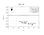
- FIGS. 11 a and 11 b are graphs showing pH and ORP properties of reducing water produced in the cathode before and after electrode interchange in the apparatus for producing reducing water described in FIGS. 6 a and 6 b.
- FIG. 11 a shows variation in pH of reducing water according to deterioration in performance of the cation exchange resin, while water flows at a predetermined flow rate.
- water emitted from the cathode exhibits an increase in pH due to deterioration in performance of the cation exchange resin.
- the cathode and the anode used for the electrolytic bath may have a plurality of pores, through which water passes, as shown in FIGS. 12 a and 12 b , wherein the pores are spaced from one another by a predetermined distance ( FIG. 12 a ), or may be a mesh (net) structure in order to further increase surface area ( FIG. 12 b ).
- a material for electrodes may be a biologically stable titanium electrode coated with platinum that does not cause ionization reaction due to applied voltage, exhibits superior electrical conductivity and is biologically stable.
- the cathode and the cation exchange membrane may contact the cation exchange resin, and the cation exchange resin and the cation exchange membrane may contact the anode.
- FIG. 13 is a view illustrating configurations of a cation exchange resin, a cation exchange membrane and electrodes in the apparatus for producing reducing water according to the embodiment of the present disclosure.
- the cation exchange resin 86 , the cation exchange membranes 85 and 85 ′ and the electrodes 83 and 84 contact one another. Also, since only cations are passed through the cation exchange membranes 85 and 85 ′, water cannot be moved through the cation exchange membrane. Accordingly, an area in which water is contained is divided based on the cation exchange membrane.
- the apparatus for producing reducing water is capable of producing neutral (pH 5.8 ⁇ 8.5) reducing water.
- the apparatus may be applied to dispensers or indoor humidifiers of household and business refrigerators.
- the reducing water produced by the apparatus is highly active reducing water that has a maximized H 2 dissolved level at room temperature and contains finely cleaved water molecules, thus being utilized in a variety of applications including health, cosmetics, and agricultural fields.
Landscapes
- Engineering & Computer Science (AREA)
- Water Supply & Treatment (AREA)
- Chemical & Material Sciences (AREA)
- Chemical Kinetics & Catalysis (AREA)
- Health & Medical Sciences (AREA)
- Urology & Nephrology (AREA)
- Electrochemistry (AREA)
- General Chemical & Material Sciences (AREA)
- Life Sciences & Earth Sciences (AREA)
- Hydrology & Water Resources (AREA)
- Environmental & Geological Engineering (AREA)
- Organic Chemistry (AREA)
- Water Treatment By Electricity Or Magnetism (AREA)
Abstract
Description
Cathode (−electrode): 2H2O+2e −→H2+2OH−, E0=−0.828V
Anode (+electrode): 4H++O2+4e −→2H2O, E0=+1.229V [Reaction Scheme 1]
wherein n represents a number of reacted electrons, H2-standard hydrogen electrode and H2-cathode represent a H2 concentration (mol/L) of a standard hydrogen electrode and a H2 concentration (mol/L) of a cathode, respectively, and OH− represents a concentration of OH− (mol/L).
OH− (generated in cathode)+H+ (transferred from anode and cation exchange resin)→H2O (neutral water) [Reaction Scheme 2]
OH− (generated in cathode)+H+ (transferred from anode and cation exchange resin)→H2O (neutral water) [Reaction Scheme 2]
Claims (5)
Applications Claiming Priority (4)
| Application Number | Priority Date | Filing Date | Title |
|---|---|---|---|
| KR10-2011-0100967 | 2011-10-05 | ||
| KR20110100967 | 2011-10-05 | ||
| KR1020120093967A KR101987645B1 (en) | 2011-10-05 | 2012-08-27 | Apparatus for producing reducing water by electrolysis |
| KR10-2012-0093967 | 2012-08-27 |
Publications (2)
| Publication Number | Publication Date |
|---|---|
| US20130087488A1 US20130087488A1 (en) | 2013-04-11 |
| US10167207B2 true US10167207B2 (en) | 2019-01-01 |
Family
ID=47071132
Family Applications (1)
| Application Number | Title | Priority Date | Filing Date |
|---|---|---|---|
| US13/627,440 Expired - Fee Related US10167207B2 (en) | 2011-10-05 | 2012-09-26 | Electrolytic apparatus with circulator, reverse osmosis filter, and cooler, for producing reducing water |
Country Status (4)
| Country | Link |
|---|---|
| US (1) | US10167207B2 (en) |
| EP (1) | EP2578542B1 (en) |
| CN (1) | CN103101994B (en) |
| WO (1) | WO2013051810A2 (en) |
Families Citing this family (5)
| Publication number | Priority date | Publication date | Assignee | Title |
|---|---|---|---|---|
| JP6196528B2 (en) * | 2013-10-30 | 2017-09-13 | 株式会社日本トリム | Dissolved hydrogen concentration measuring method and electrolyzed water generator |
| CN207031036U (en) * | 2014-09-22 | 2018-02-23 | 株式会社东芝 | Electrolysis unit |
| CN107287609B (en) * | 2016-04-13 | 2018-09-07 | 上海紫盒生物科技有限公司 | Continuity hydrogen-rich water preparation apparatus for household RO water purification machines |
| JP6612714B2 (en) * | 2016-10-31 | 2019-11-27 | 株式会社東芝 | Electrolyzed water generator |
| CN107059041A (en) * | 2017-04-26 | 2017-08-18 | 深圳市量子水生态科技有限公司 | A kind of method for the hydroxyl radical negative ion water for preparing degreasing cleaning and sterilizing |
Citations (21)
| Publication number | Priority date | Publication date | Assignee | Title |
|---|---|---|---|---|
| US3305306A (en) * | 1962-04-03 | 1967-02-21 | Benckiser Gmbh Joh A | Process of selectively recovering metal ions from solutions containing same |
| GB2197307A (en) * | 1986-09-09 | 1988-05-18 | British Nuclear Fuels Plc | An improved method of filtration in an ion exchange process |
| US4803089A (en) | 1984-03-02 | 1989-02-07 | Nestec S.A. | Process for treating dairy by-products |
| WO1991002584A1 (en) | 1989-08-14 | 1991-03-07 | Allied-Signal Inc. | Electrodialytic treatment of aqueous solutions containing amino acids |
| JPH07966A (en) | 1991-12-27 | 1995-01-06 | Nobuo Sumida | Liquid coexisting hydrogen ion or hydroxide ion with oxidizing-reducing material by electrolyzing pure water and its production |
| RU2060231C1 (en) | 1989-10-20 | 1996-05-20 | Ибара Корпорейшн | Ion-exchange resin as polymer adsorbent and method for absorbing and removing of contaminants |
| US5593554A (en) | 1994-10-28 | 1997-01-14 | Organo Corporation | Electrolytic ionized water producing apparatus |
| RU2105725C1 (en) | 1997-04-30 | 1998-02-27 | Научно-производственная фирма "ВОЛТЭК" | Method of isolating ions from aqueous solutions |
| US6080313A (en) * | 1997-08-29 | 2000-06-27 | Kelada; Maher I. | Point-of-use water purification system with a cascade ion exchange option |
| US6143163A (en) | 1997-08-06 | 2000-11-07 | Permelec Electrode Ltd. | Method of water electrolysis |
| EP1293481A2 (en) | 2001-09-14 | 2003-03-19 | Coherent Technology Co., Ltd. | Electrolytic cell for producing charged anode water suitable for surface cleaning or treatment, and method for producing the same and use of the same |
| US20060091013A1 (en) * | 2002-12-27 | 2006-05-04 | Ebara Corporation | Electric demineralizer |
| WO2008015867A1 (en) | 2006-08-04 | 2008-02-07 | Spring Co., Ltd. | Method for activating and stabilizing dissolved hydrogen in water |
| US20080299432A1 (en) * | 2005-09-08 | 2008-12-04 | Airbus Deutschland Gmbh | Fuel Cell System for the Supply of Drinking Water and Oxygen |
| US20080302651A1 (en) * | 2004-08-11 | 2008-12-11 | Miz Co., Ltd. | Performance Maintaining Method For Electrolyzed Functional Water Generating Apparatus |
| KR20100021302A (en) | 2008-08-14 | 2010-02-24 | 웅진코웨이주식회사 | A soft water apparatus |
| US20100062113A1 (en) | 2006-11-24 | 2010-03-11 | Osao Sumita | Hydrogen-dissolved aqueous solution and method for prolonging the life duration of hydrogen dissolved in the aqueous solution |
| EP2179971A1 (en) | 2007-04-13 | 2010-04-28 | Yusho Arai | Apparatus for producing electrolyzed water, method for producing electrolyzed water, and electrolyzed water |
| US20110129758A1 (en) * | 2008-09-05 | 2011-06-02 | Waterware Inc. | Water electrolysis apparatus and water electrolysis system |
| EP2338841A1 (en) | 2008-10-17 | 2011-06-29 | Spring Co., Ltd. | Apparatus for producing hydrogen-dissolved drinking water and process for producing the dissolved drinking water |
| EP2508482A1 (en) | 2011-04-08 | 2012-10-10 | Samsung Electronics Co., Ltd. | Apparatus and method for electrolytic production of reducing water |
-
2012
- 2012-09-26 WO PCT/KR2012/007730 patent/WO2013051810A2/en not_active Ceased
- 2012-09-26 US US13/627,440 patent/US10167207B2/en not_active Expired - Fee Related
- 2012-10-05 EP EP12187506.6A patent/EP2578542B1/en not_active Not-in-force
- 2012-10-08 CN CN201210377698.XA patent/CN103101994B/en not_active Expired - Fee Related
Patent Citations (27)
| Publication number | Priority date | Publication date | Assignee | Title |
|---|---|---|---|---|
| US3305306A (en) * | 1962-04-03 | 1967-02-21 | Benckiser Gmbh Joh A | Process of selectively recovering metal ions from solutions containing same |
| US4803089A (en) | 1984-03-02 | 1989-02-07 | Nestec S.A. | Process for treating dairy by-products |
| GB2197307A (en) * | 1986-09-09 | 1988-05-18 | British Nuclear Fuels Plc | An improved method of filtration in an ion exchange process |
| WO1991002584A1 (en) | 1989-08-14 | 1991-03-07 | Allied-Signal Inc. | Electrodialytic treatment of aqueous solutions containing amino acids |
| US5049250A (en) | 1989-08-14 | 1991-09-17 | Allied-Signal Inc. | Electrodialytic treatment of aqueous solutions containing amino acids |
| RU2060231C1 (en) | 1989-10-20 | 1996-05-20 | Ибара Корпорейшн | Ion-exchange resin as polymer adsorbent and method for absorbing and removing of contaminants |
| JPH07966A (en) | 1991-12-27 | 1995-01-06 | Nobuo Sumida | Liquid coexisting hydrogen ion or hydroxide ion with oxidizing-reducing material by electrolyzing pure water and its production |
| US5593554A (en) | 1994-10-28 | 1997-01-14 | Organo Corporation | Electrolytic ionized water producing apparatus |
| RU2105725C1 (en) | 1997-04-30 | 1998-02-27 | Научно-производственная фирма "ВОЛТЭК" | Method of isolating ions from aqueous solutions |
| US6143163A (en) | 1997-08-06 | 2000-11-07 | Permelec Electrode Ltd. | Method of water electrolysis |
| US6080313A (en) * | 1997-08-29 | 2000-06-27 | Kelada; Maher I. | Point-of-use water purification system with a cascade ion exchange option |
| US20030056805A1 (en) * | 2001-09-14 | 2003-03-27 | Osao Sumita | Electrolytic cell for producing charged anode water suitable for surface cleaning or treatment, and method for producing the same and use of the same |
| EP1293481A2 (en) | 2001-09-14 | 2003-03-19 | Coherent Technology Co., Ltd. | Electrolytic cell for producing charged anode water suitable for surface cleaning or treatment, and method for producing the same and use of the same |
| US20060091013A1 (en) * | 2002-12-27 | 2006-05-04 | Ebara Corporation | Electric demineralizer |
| US20080302651A1 (en) * | 2004-08-11 | 2008-12-11 | Miz Co., Ltd. | Performance Maintaining Method For Electrolyzed Functional Water Generating Apparatus |
| US20080299432A1 (en) * | 2005-09-08 | 2008-12-04 | Airbus Deutschland Gmbh | Fuel Cell System for the Supply of Drinking Water and Oxygen |
| WO2008015867A1 (en) | 2006-08-04 | 2008-02-07 | Spring Co., Ltd. | Method for activating and stabilizing dissolved hydrogen in water |
| US20100062113A1 (en) | 2006-11-24 | 2010-03-11 | Osao Sumita | Hydrogen-dissolved aqueous solution and method for prolonging the life duration of hydrogen dissolved in the aqueous solution |
| EP2179971A1 (en) | 2007-04-13 | 2010-04-28 | Yusho Arai | Apparatus for producing electrolyzed water, method for producing electrolyzed water, and electrolyzed water |
| US20100200425A1 (en) | 2007-04-13 | 2010-08-12 | Yusho Arai | Electrolyzed water manufacturing device, electrolyzed water manufacturing method, and electrolyzed water |
| KR20100021302A (en) | 2008-08-14 | 2010-02-24 | 웅진코웨이주식회사 | A soft water apparatus |
| US20110129758A1 (en) * | 2008-09-05 | 2011-06-02 | Waterware Inc. | Water electrolysis apparatus and water electrolysis system |
| EP2338841A1 (en) | 2008-10-17 | 2011-06-29 | Spring Co., Ltd. | Apparatus for producing hydrogen-dissolved drinking water and process for producing the dissolved drinking water |
| KR20110082568A (en) | 2008-10-17 | 2011-07-19 | 유겐가이샤 스프링 | Apparatus for producing dissolved hydrogen beverage and method for manufacturing same |
| US20110198236A1 (en) | 2008-10-17 | 2011-08-18 | Spring Co., Ltd. | Apparatus and method for producing hydrogen-dissolved drinking water |
| CN102186781A (en) | 2008-10-17 | 2011-09-14 | 有限会社春天 | Apparatus for producing hydrogen-dissolved drinking water and process for producing the dissolved drinking water |
| EP2508482A1 (en) | 2011-04-08 | 2012-10-10 | Samsung Electronics Co., Ltd. | Apparatus and method for electrolytic production of reducing water |
Non-Patent Citations (12)
| Title |
|---|
| Australian Office Action dated Mar. 12, 2015 in corresponding Australian Patent Application No. 2012319378. |
| Canadian Notice of Allowance dated Jun. 30, 2017 in the related Canadian Application No. 2,850,463. |
| Canadian Office Action dated Nov. 7, 2016 from Canadian Patent Application No. 2,850,463. |
| Chinese Office Action dated Apr. 15, 2015 issued in corresponding Chinese Patent Application No. 201210377698.X (10 pages). |
| Communication under Rule 71(3) dated Nov. 7, 2017 in corresponding European Patent Application No. 12 187 506.6, 46 pages. |
| European Office Action dated May 29, 2017 in the related European Application No. 12 187 506.6. |
| European Office Action dated Oct. 19, 2016 from European Patent Application No. 12 187 506.6. |
| Indian Office Action dated Apr. 18, 2018 issued in corresponding Indian Patent Application No. 2634/DELNP/2014 (6 pages). |
| International Search Report dated Mar. 22, 2013 for corresponding International Application No. PCT/KR2012/007730. |
| Korean Patent Office Action issued in Korean Patent Application No. 10- 2012-0093967 dated Sep. 3, 2018 (15 Total No. pages). |
| Partial European Search Report dated Jan. 25, 2013 for corresponding European Application No. 12187506.6. |
| Russian Office Action dated Mar. 18, 2015 in corresponding Russian Patent Application No. 2014113267/05(020773). |
Also Published As
| Publication number | Publication date |
|---|---|
| EP2578542A2 (en) | 2013-04-10 |
| WO2013051810A3 (en) | 2013-07-04 |
| EP2578542B1 (en) | 2018-04-18 |
| WO2013051810A2 (en) | 2013-04-11 |
| CN103101994B (en) | 2016-08-17 |
| US20130087488A1 (en) | 2013-04-11 |
| CN103101994A (en) | 2013-05-15 |
| EP2578542A3 (en) | 2013-06-26 |
Similar Documents
| Publication | Publication Date | Title |
|---|---|---|
| JP5361325B2 (en) | Dissolved hydrogen drinking water manufacturing apparatus and manufacturing method thereof | |
| JP3988827B2 (en) | Method and apparatus for producing negative and positive redox potential (ORP) water | |
| US20130092558A1 (en) | Apparatus for producing electrolytic reduced water and control method thereof | |
| US10167207B2 (en) | Electrolytic apparatus with circulator, reverse osmosis filter, and cooler, for producing reducing water | |
| JP5764474B2 (en) | Electrolytic synthesis apparatus, electrolytic treatment apparatus, electrolytic synthesis method, and electrolytic treatment method | |
| JP5858304B2 (en) | Acid water electrolyzer and method of using the acid water | |
| US20110108437A1 (en) | Disinfection method and disinfection device | |
| JP2005058848A (en) | Production method for water used for washing, disinfecting, and wound healing, its production apparatus, and water used for washing, disinfecting, and wound healing | |
| US20120255873A1 (en) | Apparatus and method for producing electrolytic reducing water | |
| JP5882025B2 (en) | Hydrogen water production apparatus and hydrogen water production method | |
| US20130092530A1 (en) | Apparatus for producing electrolytic reduced water and control method thereof | |
| US9464358B2 (en) | Electrolytic magnetic cell device and a method for producing hypochlorous acid and other disinfectant chlorine oxidants | |
| Ghernaout et al. | Towards combining electrochemical water splitting and electrochemical disinfection | |
| JPH11128940A (en) | Device and method for electrolysis of water | |
| AU2012319378B2 (en) | Apparatus for producing reducing water | |
| CN111763952B (en) | A desalination method and device for producing ultra-high purity hypochlorous acid aqueous solution using salt as raw material | |
| RU2351546C2 (en) | Method for reduction of oxidation-reduction potential of water | |
| KR102289793B1 (en) | Method for producing electrolytic water for sterilization and device for producing same | |
| AU2012201437B2 (en) | Method and apparatus for producing negative and positive oxidative reductive potential (ORP) water |
Legal Events
| Date | Code | Title | Description |
|---|---|---|---|
| AS | Assignment |
Owner name: SAMSUNG ELECTRONICS CO., LTD., KOREA, REPUBLIC OF Free format text: ASSIGNMENT OF ASSIGNORS INTEREST;ASSIGNORS:KWAK, HYUN SUK;KO, YOUNG CHUL;YUN, YOUNG UK;AND OTHERS;REEL/FRAME:029182/0368 Effective date: 20120925 |
|
| STCF | Information on status: patent grant |
Free format text: PATENTED CASE |
|
| FEPP | Fee payment procedure |
Free format text: MAINTENANCE FEE REMINDER MAILED (ORIGINAL EVENT CODE: REM.); ENTITY STATUS OF PATENT OWNER: LARGE ENTITY |
|
| LAPS | Lapse for failure to pay maintenance fees |
Free format text: PATENT EXPIRED FOR FAILURE TO PAY MAINTENANCE FEES (ORIGINAL EVENT CODE: EXP.); ENTITY STATUS OF PATENT OWNER: LARGE ENTITY |
|
| STCH | Information on status: patent discontinuation |
Free format text: PATENT EXPIRED DUE TO NONPAYMENT OF MAINTENANCE FEES UNDER 37 CFR 1.362 |
|
| FP | Lapsed due to failure to pay maintenance fee |
Effective date: 20230101 |