US10166622B2 - Automatic welding method and apparatus - Google Patents
Automatic welding method and apparatus Download PDFInfo
- Publication number
- US10166622B2 US10166622B2 US13/513,001 US201013513001A US10166622B2 US 10166622 B2 US10166622 B2 US 10166622B2 US 201013513001 A US201013513001 A US 201013513001A US 10166622 B2 US10166622 B2 US 10166622B2
- Authority
- US
- United States
- Prior art keywords
- wire
- interaction position
- welding
- zones
- wire interaction
- Prior art date
- Legal status (The legal status is an assumption and is not a legal conclusion. Google has not performed a legal analysis and makes no representation as to the accuracy of the status listed.)
- Active, expires
Links
Images


Classifications
-
- B—PERFORMING OPERATIONS; TRANSPORTING
- B23—MACHINE TOOLS; METAL-WORKING NOT OTHERWISE PROVIDED FOR
- B23K—SOLDERING OR UNSOLDERING; WELDING; CLADDING OR PLATING BY SOLDERING OR WELDING; CUTTING BY APPLYING HEAT LOCALLY, e.g. FLAME CUTTING; WORKING BY LASER BEAM
- B23K9/00—Arc welding or cutting
- B23K9/095—Monitoring or automatic control of welding parameters
- B23K9/0956—Monitoring or automatic control of welding parameters using sensing means, e.g. optical
-
- B—PERFORMING OPERATIONS; TRANSPORTING
- B23—MACHINE TOOLS; METAL-WORKING NOT OTHERWISE PROVIDED FOR
- B23K—SOLDERING OR UNSOLDERING; WELDING; CLADDING OR PLATING BY SOLDERING OR WELDING; CUTTING BY APPLYING HEAT LOCALLY, e.g. FLAME CUTTING; WORKING BY LASER BEAM
- B23K26/00—Working by laser beam, e.g. welding, cutting or boring
- B23K26/14—Working by laser beam, e.g. welding, cutting or boring using a fluid stream, e.g. a jet of gas, in conjunction with the laser beam; Nozzles therefor
- B23K26/1462—Nozzles; Features related to nozzles
- B23K26/1464—Supply to, or discharge from, nozzles of media, e.g. gas, powder, wire
- B23K26/147—Features outside the nozzle for feeding the fluid stream towards the workpiece
-
- B—PERFORMING OPERATIONS; TRANSPORTING
- B23—MACHINE TOOLS; METAL-WORKING NOT OTHERWISE PROVIDED FOR
- B23K—SOLDERING OR UNSOLDERING; WELDING; CLADDING OR PLATING BY SOLDERING OR WELDING; CUTTING BY APPLYING HEAT LOCALLY, e.g. FLAME CUTTING; WORKING BY LASER BEAM
- B23K9/00—Arc welding or cutting
- B23K9/12—Automatic feeding or moving of electrodes or work for spot or seam welding or cutting
- B23K9/124—Circuits or methods for feeding welding wire
- B23K9/125—Feeding of electrodes
-
- B—PERFORMING OPERATIONS; TRANSPORTING
- B23—MACHINE TOOLS; METAL-WORKING NOT OTHERWISE PROVIDED FOR
- B23K—SOLDERING OR UNSOLDERING; WELDING; CLADDING OR PLATING BY SOLDERING OR WELDING; CUTTING BY APPLYING HEAT LOCALLY, e.g. FLAME CUTTING; WORKING BY LASER BEAM
- B23K9/00—Arc welding or cutting
- B23K9/16—Arc welding or cutting making use of shielding gas
- B23K9/167—Arc welding or cutting making use of shielding gas and of a non-consumable electrode
-
- B—PERFORMING OPERATIONS; TRANSPORTING
- B23—MACHINE TOOLS; METAL-WORKING NOT OTHERWISE PROVIDED FOR
- B23K—SOLDERING OR UNSOLDERING; WELDING; CLADDING OR PLATING BY SOLDERING OR WELDING; CUTTING BY APPLYING HEAT LOCALLY, e.g. FLAME CUTTING; WORKING BY LASER BEAM
- B23K9/00—Arc welding or cutting
- B23K9/16—Arc welding or cutting making use of shielding gas
- B23K9/173—Arc welding or cutting making use of shielding gas and of a consumable electrode
Definitions
- the present invention relates to a method and apparatus for automatically controlling welding, in particular, a method and apparatus for automatically controlling welding by monitoring the wire interaction position.
- Welding is widely used in many manufacturing processes in order to join components together. If the particular welding process is carried out repeatedly then it may be carried out by a robot as opposed to by an operator. This provides a number of benefits including improved repeatability. However, it is still necessary for an operator to monitor the welding process.
- VDU visual display unit
- the operator can control the robot, the wire feed and the welding parameters.
- the operator visually determines from the VDU that the weld deposition is not ideal, the wire feed and the welding parameters are manually overridden using the teach pendant.
- the present invention provides a method of automatically controlling welding using a welding apparatus having a heat-source and a wire feed, the method comprising: setting at least one welding parameter; setting a stable wire interaction position where a wire fed by the wire feed interacts with the heat generated by the heat-source so as to produce an acceptable weld; defining a number of zones with respect to the stable wire interaction position, monitoring the wire interaction position during welding; and determining which zone the wire interaction position is located in and automatically altering at least one welding parameter to return the wire interaction position to within an allowable tolerance of the stable wire interaction position, wherein the magnitude and direction of alteration of the welding parameter is dependent on which zone the wire interaction position is located in.
- the allowable tolerance may be zero.
- the wire interaction position is monitored by a camera.
- the wire feed rate may be altered to return the wire interaction position to within an allowable tolerance of the stable wire interaction position.
- the zones can be circular.
- the zones can be concentric.
- the zones can be centred on the stable wire interaction position.
- the zones can be centred on the wire interaction position.
- the zones are concentrically arranged around the stable wire interaction point.
- the zones can include sub-zones.
- the magnitude and direction of alteration of the welding parameter is dependent on which sub-zone the wire interaction position is located in.
- each zone and or sub-zone can have a predetermined magnitude and direction for altering the welding parameter associated with it.
- the zones can be divided into quadrants.
- the quadrants can define the sub-zones.
- Each quadrant can include a plurality of sub-zones from different zones.
- the welding apparatus is a TIG welding torch arranged to generate a welding arc and the wire interaction position is a wire-arc interaction point at which the wire enters the welding arc.
- An apparatus for automatically controlling welding using a welding apparatus having a heat-source and a wire feed comprising: parameter setting device arranged for setting at least one welding parameter; wire interaction setting device arranged for setting a stable wire interaction position where the wire fed by the wire feed interacts with the heat generated by the heat-source so as to produce an acceptable weld zone defining device for defining a number of zones with respect to the stable wire interaction position; monitoring device arranged for monitoring the wire interaction position during welding; and correction device arranged to automatically alter at least one welding parameter to return the wire interaction position to within the allowable tolerance of the stable wire interaction position, wherein the magnitude and direction of alteration of the welding parameter is dependent on which zone the wire interaction position is located in.
- the allowable tolerance may be zero.
- the monitoring means is a camera.
- the wire feed rate may be altered to return the wire interaction position to within an allowable tolerance of the stable wire interaction position.
- the zones can be concentrically arranged around the stable wire interaction point.
- the zones can include sub-zones, wherein the magnitude and direction of alteration of the welding parameter is dependent on which sub-zone the wire interaction position is located in.
- the zones can be divided into quadrants which define the sub-zones.
- the welding apparatus is a TIG welding torch arranged to generate a welding arc and the wire interaction position is a wire-arc interaction point at which the wire meets the welding arc.
- the invention may comprise any combination of the features and/or limitations referred to herein, except combinations of such features as are mutually exclusive.
- FIG. 1 schematically shows a welding apparatus according to the present invention
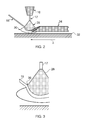
- FIG. 2 schematically shows the process of welding on a substrate
- FIG. 3 schematically shows an enlarged view of the wire-welding arc interaction
- FIG. 4 shows a flow chart of a learn mode
- FIG. 5 schematically shows the display on a VDU of the apparatus of FIG. 1 ;
- FIG. 6 schematically shows zones and quadrants centred on the nominal wire arc interaction position
- FIG. 7 shows a flow chart of an autonomous mode.
- a welding apparatus 10 comprises a robot 12 , a wire feed system 14 and a welding plant 16 that are controlled by a robot control system 18 .
- the welding plant 16 is a TIG welding torch, having a tungsten electrode 17 ( FIG. 2 ), that is mounted to the robot 12 .
- the robot control system 18 is capable of being manually controlled by an operator 24 using a hand-held teach pendant 20 and can be automatically controlled by a control system interface 22 .
- a parameter data logger 26 is connected to both the wire feed system 14 and the welding plant 16 and measures and records the values of pre-defined variables for the purposes of process traceability.
- the recorded parameters may include the voltage and current supplied to the welding plant 16 and the wire feed-rate, for example.
- the operator 24 can analyse the data recorded by the parameter data logger 26 .
- the welding torch 16 As shown in FIG. 2 , during welding on a substrate 32 in the direction A, the welding torch 16 generates a weld arc 28 which interacts with the wire 15 fed by the wire feed system 14 .
- the wire 15 becomes semi-plastic and produces a molten pool 30 . This results in a weld bead 34 being deposited on the surface of the substrate 32 .
- the position where the wire 15 interacts with the weld arc 28 is known as the wire-arc interaction point (WAIP) 36 .
- WAIP wire-arc interaction point
- the position of the WAIP 36 is monitored by a camera 38 which feeds its signal to both the control system interface 22 and a visual display unit (VDU) 40 .
- the position of the camera 38 is fixed with respect to the welding plant 16 in order to maintain a fixed view of the process set-up.
- the VDU 40 includes a user interface which feeds back into the control system interface 22 .
- the feedback loop 42 which connects the control system interface 22 to the robot control system 18 automates the welding process to ensure that the flow of wire 15 fed by the wire feed system 14 remains constant without manual process intervention. This removes the variability that would otherwise be present due to the manual operator.
- the first is a learn mode 100 in which the control system 18 learns various parameters for autonomous operation.
- the second is an autonomous mode 200 in which the welding process is carried out without operator intervention based on the parameters learnt by the control system 18 during the learn mode 100 .
- the operator selects a template 102 , which may be welding of a specific component.
- a start-up sequence 104 is run in which various parameters are input 106 to the control system 18 using the teach pendant 20 or directly into the robot control system 18 . These parameters may include the distance between the surface of the component which is to be welded and the tip of the welding torch, the angle of the wire feed relative to the surface of the component, the forward feed rate, the wire feed rate, and the distance between the tip of the wire and the tool centre point (TCP), which is the point of the component directly beneath the top of the welding torch.
- TCP tool centre point
- the input parameters are stored in a database of the robot control system 18 for the particular template selected. Welding is then commenced and the operator waits for the WAIP 36 to become stable. This is known as the process stabilisation point. The WAIP 36 will be observed by the user from the VDU 40 .
- Typical set-up parameters may be:
- the operator electronically selects it 108 and identifies it using the VDU 40 .
- This nominal stable WAIP 44 is then stored in the database of the robot control system 18 for the particular template selected.
- the component is then welded 110 based on the specific template selected.
- the camera 38 monitors the WAIP 36 and feeds this information to the control system interface 22 which in turn communicates with the robot control system 18 . If the WAIP 36 deviates from the nominal stable WAIP 44 then the wire feed rate of the wire feed system 14 is adjusted. The wire feed rate is adjusted based on an algorithm in order to return the WAIP 36 to the nominal WAIP 44 .
- the algorithm will now be described with reference to FIG. 6 .
- Five zones 0 , 1 , 2 , 3 , 4 are defined around the nominal stable WAIP 44 .
- the radius of zone 0 is equal to 10% of the wire diameter
- the radius of zone 1 is 0.5 mm
- the radius of zone 2 is 1 mm
- the radius of zone 3 is 1.5 mm
- zone 4 is anything beyond zone 3 .
- Four quadrants A, B, C, D are also defined around the nominal stable WAIP 44 .
- the wire feed rate is changed based on the location of the WAIP 36 in order to return the WAIP 36 to the nominal WAIP 44 .
- the definition of the zones and the adjustments above are based on the typical set-up parameters and they ensure that the wire 15 does not make direct contact with either the substrate 32 or the electrode 17 .
- the learn mode 100 may be repeated a number of times, for example 50 times, in order to build up the database.
- the learn mode 100 may automatically recall the start-up parameters instead of them having be input manually in step 106 .
- the operator may intervene at any time and change these parameters using the teach pendant 20 . If any changes are made by the operator, these are recorded to the database.
- the welding apparatus 10 is capable of automatically welding based on the stored welding template.
- the operator selects a template 202 and a start-up sequence 204 is run.
- the start-up sequence 204 the start-up parameters, that were learnt during the learn mode 100 , are recalled from the database and they control the start-up inputs and move the welding apparatus towards a stable state.
- the robot control system 18 sets the nominal WAIP 44 based on the information stored in the database during the learn mode 100 .
- Welding 206 is then commenced and the position of the WAIP 36 is monitored using the camera 38 .
- the wire feed rate of the wire feed system 14 is adjusted based on an algorithm in order to return the WAIP 36 to the nominal WAIP 44 .
- the algorithm used is the same as that described above for the learn mode 100 .
- the operator may manually intervene to alter the operation parameters. Any changes may be recorded in the database.
- the above described method and apparatus allows a component to be welded without an operator having to visually monitor the welding process and adjust parameters, such as the wire feed rate, in order to produce a good weld.
- the control system 18 , 22 is able to react quickly to any deviation in the WAIP 36 from the nominal WAIP 44 . This results in a consistent flow of wire fed metal during the welding process, thus improving weld quality.
- the present invention significantly decreases the need for a full time operator, decreases the amount of operator intervention and enables greater confidence in the welding process.
- the invention could also be applied to the deposition of any wire fed material (metal or plastics) that is incorporated into or becomes the final component or feature.
- Alternative heat sources to create the molten pool may be used as an alternative to the TIG welding torch, for example laser or electron beam, provided that an interaction point between the wire and the heat source can be defined.
Abstract
A method of automatically controlling welding using a welding apparatus having a heat-source and a wire feed. The method includes: setting at least one welding parameter; setting a stable wire interaction position where the wire fed by the wire feed interacts with the heat generated by the heat-source so as to produce an acceptable weld; and monitoring the wire interaction position during welding. If the wire interaction position deviates from the stable wire interaction position by more than an allowable tolerance at least one welding parameter is automatically altered to return the wire interaction position to within the allowable tolerance of the stable wire interaction position. The invention also relates to an apparatus for carrying out the method.
Description
The present invention relates to a method and apparatus for automatically controlling welding, in particular, a method and apparatus for automatically controlling welding by monitoring the wire interaction position.
Welding is widely used in many manufacturing processes in order to join components together. If the particular welding process is carried out repeatedly then it may be carried out by a robot as opposed to by an operator. This provides a number of benefits including improved repeatability. However, it is still necessary for an operator to monitor the welding process.
An operator continually visually assesses the weld deposition through monitoring a visual display unit (VDU) which is attached to a camera that is focussed on the weld point arc. Using a hand-held teach pendant that is connected to the robot, the operator can control the robot, the wire feed and the welding parameters. When the operator visually determines from the VDU that the weld deposition is not ideal, the wire feed and the welding parameters are manually overridden using the teach pendant.
For example, if the wire makes contact with the component during the welding deposition process, the integrity of the weld will be compromised at these locations. This is because the wire will not become fully molten at these locations and there is the possibility of partial wire fusion, which will affect the surface roughness of the weld deposition and the uniformity of deposition build-up. This is known as the “stubbing” effect. Further, if left unchecked, partial wire fusion can lead to the wire leaving the weld arc and solidifying on the substrate or on a previous deposited layer. This may result in activation of a robot collision control system as the robot tries to continue along a pre-programmed path. This will cause a process emergency shutdown. Therefore, when a skilled operator notices that stubbing may be about to occur, a parameter, such as the wire feed rate, is altered using the teach pendant to avoid it.
In another example, if the wire is fed in too slowly then the integrity of the deposition will be compromised at these locations. The semi-plastic relationship between the wire and the weld pool becomes intermittent and will break. This will cause an intermittent balling effect on the end of the wire, which will ultimately fall off leading to an interrupted supply of material and inconsistent weld deposition. This “blobbing” effect is known as burnback. The aforementioned effect will have an effect on subsequent deposition layers unless it is rectified by adding additional wire at those specific locations. Therefore, when a skilled operator notices that burnback may be about to occur, a parameter, such as the wire feed rate, is altered using the teach pendant to avoid it.
Whilst the manual intervention of the operator is satisfactory, it is not ideal and has a number of drawbacks. The process relies heavily on operator judgement and skill which will vary between operators. This means that the quality of the welding process may differ depending on who is operating the machine. The manual intervention also relies on the reaction time of the operator and on the system reaction time. This can result in a delay in appropriate action being taken. It also may not be possible for the operator to look at the VDU for long periods of time. This can result in the welding process having to be periodically suspended. Further, the process is reliant on the attention span of the operator which again may vary between operators.
It is therefore desirable to provide an automatic welding method and apparatus which reduces the reliance on an operator.
According to a first aspect, the present invention provides a method of automatically controlling welding using a welding apparatus having a heat-source and a wire feed, the method comprising: setting at least one welding parameter; setting a stable wire interaction position where a wire fed by the wire feed interacts with the heat generated by the heat-source so as to produce an acceptable weld; defining a number of zones with respect to the stable wire interaction position, monitoring the wire interaction position during welding; and determining which zone the wire interaction position is located in and automatically altering at least one welding parameter to return the wire interaction position to within an allowable tolerance of the stable wire interaction position, wherein the magnitude and direction of alteration of the welding parameter is dependent on which zone the wire interaction position is located in. The allowable tolerance may be zero.
Preferably the wire interaction position is monitored by a camera. The wire feed rate may be altered to return the wire interaction position to within an allowable tolerance of the stable wire interaction position.
The zones can be circular. The zones can be concentric. The zones can be centred on the stable wire interaction position. Alternatively, the zones can be centred on the wire interaction position. Preferably, the zones are concentrically arranged around the stable wire interaction point.
The zones can include sub-zones. Preferably, the magnitude and direction of alteration of the welding parameter is dependent on which sub-zone the wire interaction position is located in. In this way, each zone and or sub-zone can have a predetermined magnitude and direction for altering the welding parameter associated with it.
The zones can be divided into quadrants. The quadrants can define the sub-zones. Each quadrant can include a plurality of sub-zones from different zones.
Preferably the welding apparatus is a TIG welding torch arranged to generate a welding arc and the wire interaction position is a wire-arc interaction point at which the wire enters the welding arc.
According to a second aspect of the present invention there is provided An apparatus for automatically controlling welding using a welding apparatus having a heat-source and a wire feed, the apparatus comprising: parameter setting device arranged for setting at least one welding parameter; wire interaction setting device arranged for setting a stable wire interaction position where the wire fed by the wire feed interacts with the heat generated by the heat-source so as to produce an acceptable weld zone defining device for defining a number of zones with respect to the stable wire interaction position; monitoring device arranged for monitoring the wire interaction position during welding; and correction device arranged to automatically alter at least one welding parameter to return the wire interaction position to within the allowable tolerance of the stable wire interaction position, wherein the magnitude and direction of alteration of the welding parameter is dependent on which zone the wire interaction position is located in. The allowable tolerance may be zero.
Preferably the monitoring means is a camera. The wire feed rate may be altered to return the wire interaction position to within an allowable tolerance of the stable wire interaction position.
The zones can be concentrically arranged around the stable wire interaction point.
The zones can include sub-zones, wherein the magnitude and direction of alteration of the welding parameter is dependent on which sub-zone the wire interaction position is located in.
The zones can be divided into quadrants which define the sub-zones.
Preferably the welding apparatus is a TIG welding torch arranged to generate a welding arc and the wire interaction position is a wire-arc interaction point at which the wire meets the welding arc.
The invention may comprise any combination of the features and/or limitations referred to herein, except combinations of such features as are mutually exclusive.
Embodiments of the present invention will now be described, by way of example only, with reference to the accompanying drawings, in which:
As shown in FIG. 1 , a welding apparatus 10 comprises a robot 12, a wire feed system 14 and a welding plant 16 that are controlled by a robot control system 18. In this embodiment the welding plant 16 is a TIG welding torch, having a tungsten electrode 17 (FIG. 2 ), that is mounted to the robot 12. The robot control system 18 is capable of being manually controlled by an operator 24 using a hand-held teach pendant 20 and can be automatically controlled by a control system interface 22. A parameter data logger 26 is connected to both the wire feed system 14 and the welding plant 16 and measures and records the values of pre-defined variables for the purposes of process traceability. The recorded parameters may include the voltage and current supplied to the welding plant 16 and the wire feed-rate, for example. The operator 24 can analyse the data recorded by the parameter data logger 26.
As shown in FIG. 2 , during welding on a substrate 32 in the direction A, the welding torch 16 generates a weld arc 28 which interacts with the wire 15 fed by the wire feed system 14. The wire 15 becomes semi-plastic and produces a molten pool 30. This results in a weld bead 34 being deposited on the surface of the substrate 32.
Referring now to FIG. 3 , the position where the wire 15 interacts with the weld arc 28 is known as the wire-arc interaction point (WAIP) 36. Referring back to FIG. 1 , the position of the WAIP 36 is monitored by a camera 38 which feeds its signal to both the control system interface 22 and a visual display unit (VDU) 40. The position of the camera 38 is fixed with respect to the welding plant 16 in order to maintain a fixed view of the process set-up. The VDU 40 includes a user interface which feeds back into the control system interface 22.
During use, the feedback loop 42 which connects the control system interface 22 to the robot control system 18 automates the welding process to ensure that the flow of wire 15 fed by the wire feed system 14 remains constant without manual process intervention. This removes the variability that would otherwise be present due to the manual operator.
There are two basic modes of operation of the system 10. The first is a learn mode 100 in which the control system 18 learns various parameters for autonomous operation. The second is an autonomous mode 200 in which the welding process is carried out without operator intervention based on the parameters learnt by the control system 18 during the learn mode 100.
With reference to FIG. 4 , in the learn mode 100 the operator selects a template 102, which may be welding of a specific component.
A start-up sequence 104 is run in which various parameters are input 106 to the control system 18 using the teach pendant 20 or directly into the robot control system 18. These parameters may include the distance between the surface of the component which is to be welded and the tip of the welding torch, the angle of the wire feed relative to the surface of the component, the forward feed rate, the wire feed rate, and the distance between the tip of the wire and the tool centre point (TCP), which is the point of the component directly beneath the top of the welding torch. The input parameters are stored in a database of the robot control system 18 for the particular template selected. Welding is then commenced and the operator waits for the WAIP 36 to become stable. This is known as the process stabilisation point. The WAIP 36 will be observed by the user from the VDU 40.
Typical set-up parameters may be:
Tungsten electrode width of 2.4 mm;
Distance between the TCP and the tungsten electrode tip of 6 mm;
Wire at 45° relative to the substrate;
Forward feed of 5 mm/sec to 10 mm/sec;
Nominal wire feed rate of 0.8 m/min to 1.7 m/min;
Distance between TCP and leading edge of wire of 1 mm.
Once the WAIP 36 (FIG. 5 ) has become stable the operator electronically selects it 108 and identifies it using the VDU 40. This nominal stable WAIP 44 is then stored in the database of the robot control system 18 for the particular template selected. The component is then welded 110 based on the specific template selected. The camera 38 monitors the WAIP 36 and feeds this information to the control system interface 22 which in turn communicates with the robot control system 18. If the WAIP 36 deviates from the nominal stable WAIP 44 then the wire feed rate of the wire feed system 14 is adjusted. The wire feed rate is adjusted based on an algorithm in order to return the WAIP 36 to the nominal WAIP 44.
The algorithm will now be described with reference to FIG. 6 . Five zones 0, 1, 2, 3, 4 are defined around the nominal stable WAIP 44. The radius of zone 0 is equal to 10% of the wire diameter, the radius of zone 1 is 0.5 mm, the radius of zone 2 is 1 mm, the radius of zone 3 is 1.5 mm and zone 4 is anything beyond zone 3. Four quadrants A, B, C, D are also defined around the nominal stable WAIP 44.
The wire feed rate is changed based on the location of the WAIP 36 in order to return the WAIP 36 to the nominal WAIP 44.
-
- If the
WAIP 36 is in Zone 0 then no action is taken. - If the
WAIP 36 entersZone 4 then welding is automatically stopped. - If in Quadrant A:
- If the
And in Zone 1 then the wire feed rate (m/min) is incrementally decreased by 3.75% of the wire diameter;
And in Zone 2 then the wire feed rate (m/min) is incrementally decreased by 7.5% of the wire diameter;
And in Zone 3 then the wire feed rate (m/min) is incrementally decreased by 15% of the wire diameter.
-
- If in Quadrant B and the movement of the
WAIP 36 from thenominal WAIP 44 in the y-axis is greater than the movement of theWAIP 36 from thenominal WAIP 44 in the x-axis:
- If in Quadrant B and the movement of the
And in Zone 1 then the wire feed rate (m/min) is incrementally decreased by 3.75% of the wire diameter;
And in Zone 2 then the wire feed rate (m/min) is incrementally decreased by 7.5% of the wire diameter;
And in Zone 3 then the wire feed rate (m/min) is incrementally decreased by 15% of wire diameter.
-
- If in Quadrant B and the movement of the
WAIP 36 from thenominal WAIP 44 in the y-axis is less than the movement of theWAIP 36 from thenominal WAIP 44 in the x-axis:
- If in Quadrant B and the movement of the
And in Zone 1 then the wire feed rate (m/min) is incrementally increased by 3.75% of the wire diameter;
And in Zone 2 then the wire feed rate (m/min) is incrementally increased by 7.5% of the wire diameter;
And in Zone 3 then the wire feed rate (m/min) is incrementally increased by 15% of the wire diameter.
-
- If in Quadrant C:
And in Zone 1 then the wire feed rate (m/min) is incrementally increased by 3.75% of the wire diameter;
And in Zone 2 then the wire feed rate (m/min) is incrementally increased by 7.5% of the wire diameter;
And in Zone 3 then the wire feed rate (m/min) is incrementally increased by 15% of the wire diameter;
-
- If in Quadrant D and the movement of the
WAIP 36 from thenominal WAIP 44 in the y-axis is greater than the movement of theWAIP 36 from thenominal WAIP 44 in the x-axis:
- If in Quadrant D and the movement of the
And in Zone 1 then the wire feed rate (m/min) is incrementally increased by 3.75% of the wire diameter;
And in Zone 2 then the wire feed rate (m/min) is incrementally increased by 7.5% of the wire diameter;
And in Zone 3 then the wire feed rate (m/min) is incrementally increased by 15% of the wire diameter.
-
- If in Quadrant D and the movement of the
WAIP 36 from thenominal WAIP 44 in the y-axis is less than the movement of theWAIP 36 from thenominal WAIP 44 in the x-axis:
- If in Quadrant D and the movement of the
And in Zone 1 then the wire feed rate (m/min) is incrementally decreased by 3.75% of the wire diameter;
And in Zone 2 then the wire feed rate (m/min) is incrementally decreased by 7.5% of the wire diameter;
And in Zone 3 then the wire feed rate (m/min) is incrementally decreased by 15% of the wire diameter.
The definition of the zones and the adjustments above are based on the typical set-up parameters and they ensure that the wire 15 does not make direct contact with either the substrate 32 or the electrode 17.
For a particular welding template the learn mode 100 may be repeated a number of times, for example 50 times, in order to build up the database. When the learn mode 100 is run after the initial run for a particular welding template, it may automatically recall the start-up parameters instead of them having be input manually in step 106. However, the operator may intervene at any time and change these parameters using the teach pendant 20. If any changes are made by the operator, these are recorded to the database.
After the learn mode 100 has been run a number of times for a particular template, the welding apparatus 10 is capable of automatically welding based on the stored welding template.
Referring to FIG. 7 , in the autonomous mode 200 the operator selects a template 202 and a start-up sequence 204 is run. In the start-up sequence 204 the start-up parameters, that were learnt during the learn mode 100, are recalled from the database and they control the start-up inputs and move the welding apparatus towards a stable state. The robot control system 18 then sets the nominal WAIP 44 based on the information stored in the database during the learn mode 100. Welding 206 is then commenced and the position of the WAIP 36 is monitored using the camera 38. As described above, if the WAIP 36 deviates from the nominal stable WAIP 44 then the wire feed rate of the wire feed system 14 is adjusted based on an algorithm in order to return the WAIP 36 to the nominal WAIP 44. The algorithm used is the same as that described above for the learn mode 100.
At any point in time the operator may manually intervene to alter the operation parameters. Any changes may be recorded in the database.
The above described method and apparatus allows a component to be welded without an operator having to visually monitor the welding process and adjust parameters, such as the wire feed rate, in order to produce a good weld.
Currently the speed of parameter adjustment is restricted by the reaction time of the operator. In the present invention, the control system 18, 22 is able to react quickly to any deviation in the WAIP 36 from the nominal WAIP 44. This results in a consistent flow of wire fed metal during the welding process, thus improving weld quality. The present invention significantly decreases the need for a full time operator, decreases the amount of operator intervention and enables greater confidence in the welding process.
Although it has been described above that the wire feed rate is adjusted in order to maintain a stable WAIP, other parameters could be adjusted to obtain the same effect.
The invention could also be applied to the deposition of any wire fed material (metal or plastics) that is incorporated into or becomes the final component or feature. Alternative heat sources to create the molten pool may be used as an alternative to the TIG welding torch, for example laser or electron beam, provided that an interaction point between the wire and the heat source can be defined.
Claims (17)
1. A method of automatically controlling welding using a welding apparatus, the method comprising the following steps:
providing a heat-source that generates a welding-arc;
providing a wire feed for feeding wire to a wire interaction position, the wire interaction position being a position where the wire feed interacts with the welding-arc; and
providing a control system comprising: a pre-programmed robot control system, a control system interface, and a camera configured to record the wire interaction position and communicate the recording to the control system interface, wherein the control system is configured to:
set at least one welding parameter having an adjustable magnitude and direction;
set a stable wire interaction position with a defined tolerance, the stable wire interaction position being a position where the wire fed by the wire feed interacts with the welding-arc so as to produce a weld having pre-defined qualities;
define a number of zones with respect to the stable wire interaction position, a first zone being defined based on a diameter of the wire;
monitor whether the wire interaction position deviates from the defined tolerance of the stable wire interaction position during welding;
determine which zone the wire interaction position is located in;
automatically alter the magnitude and direction of the at least one welding parameter to return the wire interaction position to within the defined tolerance of the stable wire interaction position if the wire interaction position deviates from the defined tolerance of the stable wire interaction position during welding, wherein the alteration of the magnitude and direction of the at least one welding parameter is dependent on which of the number of defined zones the wire interaction position is located in, and the at least one welding parameter comprises at least a wire feed rate adjusted in accordance with a pre-programmed algorithm based on which of the number of defined zones the wire interaction position is located in.
2. A method according to claim 1 , wherein the defined tolerance is zero.
3. A method according to claim 1 , wherein the wire interaction position is monitored by the camera.
4. A method according to claim 1 , wherein the number of zones are concentrically arranged around the stable wire interaction position.
5. A method according to claim 1 , wherein sub-zones are defined within the number of zones and wherein the alteration of the magnitude and direction of the at least one welding parameter is dependent on which sub-zone the wire interaction position is located in.
6. A method according to claim 5 , wherein the number of zones are divided into quadrants which define the sub-zones and wherein the alteration of the magnitude and direction of the at least one welding parameter is dependent on which sub-zone the wire interaction position is located in.
7. A welding system for automatically controlling welding, the welding system comprising:
a heat-source that generates a welding-arc;
a wire feed for feeding wire to a wire interaction position, the wire interaction position being a position where the wire feed interacts with the welding-arc; and
a control system comprising: a pre-programmed robot control system, a control system interface, and a camera configured to record the wire interaction position and communicate the recording to the control system interface, wherein:
the control system is configured to:
set at least one welding parameter having an adjustable magnitude and direction;
set a stable wire interaction position with a defined tolerance, the stable wire interaction position being a position where the wire fed by the wire feed interacts with the welding-arc so as to produce a weld having pre-defined qualities;
define a number of zones with respect to the stable wire interaction position, a first zone being defined based on a diameter of the wire;
monitor whether the wire interaction position deviates from the defined tolerance of the stable wire interaction position during welding; and
alter automatically the at least one welding parameter having the adjustable magnitude and direction to return the wire interaction position to within the defined tolerance of the stable wire interaction position if the wire interaction position deviates from the defined tolerance of the stable wire interaction position during welding;
the alteration of the magnitude and direction of the at least one welding parameter is dependent on which of the number of defined zones the wire interaction position is located in; and
the at least one welding parameter comprises at least a feed rate adjusted in accordance with a pre-programmed algorithm based on which of the number of defined zones the wire interaction position is located in.
8. An apparatus according to claim 7 , wherein the defined tolerance is zero.
9. An apparatus according to claim 7 , wherein sub-zones are defined within the number of zones and wherein the alteration of the magnitude and direction of the at least one welding parameter is dependent on which sub-zone the wire interaction position is located in.
10. An apparatus according to claim 7 , wherein the number of zones are divided into quadrants which define sub-zones and wherein the alteration of the magnitude and direction of the at least one welding parameter is dependent on which sub-zone the wire interaction position is located in.
11. An apparatus according to claim 7 , wherein the heat source that generates a welding-arc is a TIG welding torch and the wire interaction position is a wire-arc interaction point at which the wire meets the welding-arc.
12. An apparatus according to claim 7 , wherein the number of zones are circular.
13. An apparatus according to claim 12 , wherein the number of zones are arranged concentrically.
14. An apparatus according to claim 7 , wherein the number of zones each have a constant radius.
15. An apparatus according to claim 7 , wherein when the wire interaction position is located in the first zone, the wire feed rate is not adjusted.
16. An apparatus according to claim 7 , wherein when the wire interaction position is located in a second zone with a radius that is greater than a radius of the first zone, the wire feed rate is incrementally decreased.
17. An apparatus according to claim 7 , wherein when the wire interaction position is located in a third zone with a radius that is greater than a radius of a second zone, the wire feed rate is zero.
Applications Claiming Priority (3)
| Application Number | Priority Date | Filing Date | Title |
|---|---|---|---|
| GB0921922.1 | 2009-12-16 | ||
| GBGB0921922.1A GB0921922D0 (en) | 2009-12-16 | 2009-12-16 | Automatic welding method and apparatus |
| PCT/EP2010/069718 WO2011073238A1 (en) | 2009-12-16 | 2010-12-15 | Automatic welding method using a welding apparatus having a heat- source and a wire feed and welding apparatus |
Publications (2)
| Publication Number | Publication Date |
|---|---|
| US20120234811A1 US20120234811A1 (en) | 2012-09-20 |
| US10166622B2 true US10166622B2 (en) | 2019-01-01 |
Family
ID=41717005
Family Applications (1)
| Application Number | Title | Priority Date | Filing Date |
|---|---|---|---|
| US13/513,001 Active 2033-01-19 US10166622B2 (en) | 2009-12-16 | 2010-12-15 | Automatic welding method and apparatus |
Country Status (4)
| Country | Link |
|---|---|
| US (1) | US10166622B2 (en) |
| EP (1) | EP2512718A1 (en) |
| GB (1) | GB0921922D0 (en) |
| WO (1) | WO2011073238A1 (en) |
Families Citing this family (1)
| Publication number | Priority date | Publication date | Assignee | Title |
|---|---|---|---|---|
| US20160339533A1 (en) * | 2015-05-18 | 2016-11-24 | Abb Technology Ag | Robotically controlled gas tungsten arc welder and method for operating the same |
Citations (6)
| Publication number | Priority date | Publication date | Assignee | Title |
|---|---|---|---|---|
| JPS5886982A (en) | 1981-11-20 | 1983-05-24 | Ishikawajima Harima Heavy Ind Co Ltd | Controller for position of wire in welding machine |
| US4737614A (en) | 1986-04-22 | 1988-04-12 | The Ohio State University Research Foundation | Optical image control for automated arc welding system vision system |
| US4918517A (en) | 1989-01-26 | 1990-04-17 | Westinghouse Electric Corp. | System and process for video monitoring a welding operation |
| US20050103766A1 (en) * | 2002-03-04 | 2005-05-19 | Takahisa Iizuka | Automatic groove copy welder and welding method |
| US20060201915A1 (en) | 2005-03-09 | 2006-09-14 | Takeshi Obana | Welding process for stainless steel piping |
| WO2008015353A1 (en) * | 2006-08-03 | 2008-02-07 | L'air Liquide Societe Anonyme Pour L'etude Et L'exploitation Des Procedes Georges Claude | Tig braze-welding with metal transfer in drops at a controlled frequency |
Family Cites Families (1)
| Publication number | Priority date | Publication date | Assignee | Title |
|---|---|---|---|---|
| WO2006083010A1 (en) * | 2005-02-02 | 2006-08-10 | Ajinomoto Co., Inc. | Process for production of 4-acetylpyrimidines and crystals thereof |
-
2009
- 2009-12-16 GB GBGB0921922.1A patent/GB0921922D0/en not_active Ceased
-
2010
- 2010-12-15 US US13/513,001 patent/US10166622B2/en active Active
- 2010-12-15 EP EP10795306A patent/EP2512718A1/en not_active Withdrawn
- 2010-12-15 WO PCT/EP2010/069718 patent/WO2011073238A1/en active Application Filing
Patent Citations (7)
| Publication number | Priority date | Publication date | Assignee | Title |
|---|---|---|---|---|
| JPS5886982A (en) | 1981-11-20 | 1983-05-24 | Ishikawajima Harima Heavy Ind Co Ltd | Controller for position of wire in welding machine |
| US4737614A (en) | 1986-04-22 | 1988-04-12 | The Ohio State University Research Foundation | Optical image control for automated arc welding system vision system |
| US4918517A (en) | 1989-01-26 | 1990-04-17 | Westinghouse Electric Corp. | System and process for video monitoring a welding operation |
| US20050103766A1 (en) * | 2002-03-04 | 2005-05-19 | Takahisa Iizuka | Automatic groove copy welder and welding method |
| US20060201915A1 (en) | 2005-03-09 | 2006-09-14 | Takeshi Obana | Welding process for stainless steel piping |
| WO2008015353A1 (en) * | 2006-08-03 | 2008-02-07 | L'air Liquide Societe Anonyme Pour L'etude Et L'exploitation Des Procedes Georges Claude | Tig braze-welding with metal transfer in drops at a controlled frequency |
| US20100012638A1 (en) * | 2006-08-03 | 2010-01-21 | Air Liquide Welding France | TIG Braze-Welding With Metal Transfer In Drops At A Controlled Frequency |
Non-Patent Citations (3)
| Title |
|---|
| French to English Machine translation of WO 2008015353. * |
| International Search Report issued in International Patent Application No. PCT/EP2010/069718 dated Apr. 19, 2011. |
| Written Opinion of the International Searching Authority issued in International Patent Application No. PCT/EP2010/069718 dated Apr. 19, 2011. |
Also Published As
| Publication number | Publication date |
|---|---|
| US20120234811A1 (en) | 2012-09-20 |
| EP2512718A1 (en) | 2012-10-24 |
| WO2011073238A1 (en) | 2011-06-23 |
| GB0921922D0 (en) | 2010-02-03 |
Similar Documents
| Publication | Publication Date | Title |
|---|---|---|
| US9511442B2 (en) | Adaptable rotating arc welding method and system | |
| US20030222059A1 (en) | High energy beam cladding | |
| CN110997218A (en) | Coaxial laser heating filament head | |
| JP2018158382A (en) | Systems and methods providing location feedback for additive manufacturing | |
| US20150129582A1 (en) | System and method for automatic height adjustment of a torch | |
| EP3385023B1 (en) | Systems for and method of arc welding with wire manipulation control | |
| US10766089B2 (en) | Heat input control for welding systems | |
| EP3676040B1 (en) | Systems and method for adaptive control of wire preheating | |
| US20150076128A1 (en) | Weld monitoring apparatus | |
| US20210370442A1 (en) | Method for producing metal structures | |
| US10166622B2 (en) | Automatic welding method and apparatus | |
| US20200331098A1 (en) | Laser clad-welding method and laser clad-welding apparatus | |
| US6518541B1 (en) | Duty cycle stabilization in direct metal deposition (DMD) systems | |
| KR102518350B1 (en) | Welding process and welding device for carrying out the welding process | |
| KR20140070836A (en) | Automatic welding device and welding method using the same | |
| US20220274202A1 (en) | Additive manufacturing machine | |
| JP4781722B2 (en) | Laser piercing method and processing apparatus | |
| CN109937112A (en) | The display device and display methods of arc welding | |
| CN115867407A (en) | Machine learning device, laminate modeling system, machine learning method for welding conditions, adjustment method for welding conditions, and program | |
| KR101798932B1 (en) | Feeding device of filler metal for welding | |
| KR20140133643A (en) | method of auto TIG welding of pipes | |
| US20240051052A1 (en) | Method for manufacturing additively-manufactured object | |
| CN114340827B (en) | Method and welding device for carrying out a multiple welding method | |
| US20220161346A1 (en) | Multiple pulsed welding method | |
| JPS5849354B2 (en) | If you have any questions or concerns, please do not hesitate to contact us. |
Legal Events
| Date | Code | Title | Description |
|---|---|---|---|
| AS | Assignment |
Owner name: ROLLS-ROYCE PLC, GREAT BRITAIN Free format text: ASSIGNMENT OF ASSIGNORS INTEREST;ASSIGNORS:KUTSCHERAWY, ALEXANDER;MANDE, AJAY RATNAKAR;SIGNING DATES FROM 20120521 TO 20120522;REEL/FRAME:028332/0310 |
|
| STCF | Information on status: patent grant |
Free format text: PATENTED CASE |
|
| MAFP | Maintenance fee payment |
Free format text: PAYMENT OF MAINTENANCE FEE, 4TH YEAR, LARGE ENTITY (ORIGINAL EVENT CODE: M1551); ENTITY STATUS OF PATENT OWNER: LARGE ENTITY Year of fee payment: 4 |