US1016509A - Sand-feeding device. - Google Patents
Sand-feeding device. Download PDFInfo
- Publication number
- US1016509A US1016509A US62652811A US1911626528A US1016509A US 1016509 A US1016509 A US 1016509A US 62652811 A US62652811 A US 62652811A US 1911626528 A US1911626528 A US 1911626528A US 1016509 A US1016509 A US 1016509A
- Authority
- US
- United States
- Prior art keywords
- sand
- screen
- casing
- wet
- separating
- Prior art date
- Legal status (The legal status is an assumption and is not a legal conclusion. Google has not performed a legal analysis and makes no representation as to the accuracy of the status listed.)
- Expired - Lifetime
Links
- 239000004576 sand Substances 0.000 description 44
- 238000010276 construction Methods 0.000 description 3
- 230000003137 locomotive effect Effects 0.000 description 3
- 210000005069 ears Anatomy 0.000 description 2
- 229910001018 Cast iron Inorganic materials 0.000 description 1
- 238000005452 bending Methods 0.000 description 1
- 238000004140 cleaning Methods 0.000 description 1
- 230000005484 gravity Effects 0.000 description 1
- 239000010985 leather Substances 0.000 description 1
- 239000002184 metal Substances 0.000 description 1
- 229910052751 metal Inorganic materials 0.000 description 1
- 239000002245 particle Substances 0.000 description 1
Images


Classifications
-
- B—PERFORMING OPERATIONS; TRANSPORTING
- B60—VEHICLES IN GENERAL
- B60B—VEHICLE WHEELS; CASTORS; AXLES FOR WHEELS OR CASTORS; INCREASING WHEEL ADHESION
- B60B39/00—Increasing wheel adhesion
- B60B39/02—Vehicle fittings for scattering or dispensing material in front of its wheels
- B60B39/04—Vehicle fittings for scattering or dispensing material in front of its wheels the material being granular, e.g. sand
Definitions
- the invention relates to devices for feeding sand and more especially to devices for separating the dry sand from the wet sand, so as to prevent the clogging of the air sanders or other valves used or the pipes leading to the track to be sanded.
- An object of the invention is to provide a separating device for the sand, which shall be so constructed as to cause the dry sand to separate from the wet portions, and also to cause the dry sand as it is discharged from the sand-separating and feeding device to break up the wet portions of the sand, and carry the same along with the discharge or flow of the dry sand.
- a further object of the invention is to provide a dry sand separating device which may be readily cleaned or emptied of the wet sand, which may lodge therein.
- Figure I is a view showing a locomotive in side elevation, with my improved sanding device applied thereto.
- Fig. II is a vertical sectional view through the improved dry sand separating device.
- Fig. III is a bottom plan view ofthe same.
- Fig. IV is a sectional view on the line IV, IV, of Fig. II.
- Fig. V is a sectional view on the line V, V, of Fig. II, and
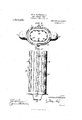
- Fig. VI is a side elevation of the screen for separating the dry sand from the wet sand.
- the dry sand separating device consists of a casing 1, which is preferably formed.
- This receptacle is approximately elliptical in cross section, as clearly shown in Fig. V.
- An opening 2 is formed at the top of the casing 1, into which is threaded an inlet or receiving pipe 3.
- This receiving pipe 3, extends to a sand dome 1, when the device is applied to a locomotive.
- the inlet or receiving pipe 3 is connected to any suitable storage receptacle for the sand.
- the inlet pipe 3, is preferably provided with a valve 5, whereby said pipe may be closed when it is desired to clean the dry sand separating receptacle.
- I have provided the lower part of the casing 1, with two outlets 6, and 7 These outlets are connected with pipes 8, and 9. Pipes 8, and 9, lead to chambers from which the sand is forced by compressed air through the pipes 10, and 11, which respectively lead to the front and rear drivers of the locomotive.
- the sand is led from the storage receptacle 4, through the receiving pipe 3, into the top of the casing 1.
- the casing 1 is formed with an opening 12, at the bottom thereof.
- the outlets 6, and 7, project from the casing, so that the opening 12, in the bottom of the casing is only slightly smaller than the casing in cross sectional area.
- a screen 13 Located within the casing is a screen 13. This screen is shaped to conform to the easing, and fits within the opening 12, in the base of the casing. The screen also extends from the base of the casin g to the upper wall thereof. When the screen is in place, the side walls thereof are spaced a slight distance from the side walls of the casing 1. The side walls of the screen 13, are formed with vertical slots 14:, which are arranged in lines extending from the bottom of the screen to the upper end thereof. The screen is formed by bending a fiat sheet metal plate into proper shape and joining the edges thereof by a small bolt 15.
- the screen at its lower end is riveted to a bottom plate 16, which projects beyond the side edges of the screen, and when the same is placed in the casing 1, the bottom engages and overlaps the bottom portion of the casing.
- a suitable rubber or leather gasket may be used if desired, to form a tight joint between the bottom of the screen and the bottom of the easing.
- the screen is held in place in the casing by suitable bolts 17, which are pivoted at 18, to the casing and the shanks of the bolts are adapted to engage slotted ears 19, formed on the bottom of a screen, and winged nuts 20, on the bolts will clamp the bottom portion of the screen against the easing.
- a handle 21, is riveted to the bottom of the screen for the purpose of withdrawing the screen from the casing, when desired.
- a sand-distributing device including in combination, a vertical casing having a receiving inlet and a discharge outlet, and a separating screen within said casing having vertical walls with vertical slots formed therein.
- a sand-distributing device including in combination, a vertical casing having a receiving inlet and a discharge outlet, a separating screen located within the casing and spaced from the side walls thereof, said screen having vertical slots formed therein.
- a sand-distributing device including in combination, a vertical casing having an inlet at its upper end located centrally thereof, outlets at its lower end located at the sides thereof, a separating screen located within the casing and spaced from the side walls thereof, said screen having vertical slots formed therein, and means whereby said screen may be removed from the casing.
- a sand-distributing device including in combination, a vertical casing having an inlet at its upper end located centrally thereof, outlets at its lower end located at the sides thereof, said casing having a central opening in the bottom thereof, a screen of slightly smaller area in cross section than said casing and fitting said opening in the bottom of the.casing, bottom adapted to engage the bottom of the casing, and means for locking said bottom to the bottom of the casing, said screen having vertical slots formed therein.
- a sanding device including in combination, a vertical casing, an inlet pipe leading to the casing at the upper end thereof, and centrally thereof, a valve in said inlet pipe, outlet pipes at the lower end of said casing at the sides thereof, said casing having an opening in its bottom, a screen adapted to fit within said opening and extending to the upper wall of the casing, vertical slots formed in said screen, said screen having a bottom adapted to engage the bottom of the casing, locking bolts for holding the screen in the casing, and a handle for removing the screen from the casing.
Landscapes
- Engineering & Computer Science (AREA)
- Mechanical Engineering (AREA)
- Combined Means For Separation Of Solids (AREA)
Description
W. H. MATTHEWS, JR. SAND FEEDING DEVICE. APPLICATION FILED MAY 11, 1911.
1,01 6,509. Patented Feb. 6, 1912.
4 SHEETSSHEET 1.
g I I FIG I.
W. H. MATTHEWS, JR.
SAND FEEDING DEVICE. APPLICATION FILED MAY 11 1911.
Patented Feb. 6, 1912.
4 SHEETS-SHEET 2.
Wimeawe COLUMBIA PLANDGRAPH c0" WASHINGTON, D. c.
W. H. MATTHEWS, JR. SAND FEEDING DEVICE. APPLIGATION FILED MAY 11, 1911.
w. 1 1 W awn b4 0 M v e m. 1. a a P w W. H. MATTHEWS, JR.
SAND FEEDING DEVICE. APPLICATION FILED MAY 11, 1911.
v v/ y c AAAAAAAAAAAAAAAAAAAAAAAAAAAAAAAAAAAA c.
I Patnted Feb. 6, 1912.
' 4 SHEETS-SHIBBT 4.
Iw'wemior em/formal WILLIAM H. MATTHEWS, JR", 0]? PHILADELPHIA, PENNSYLVANIA.
SAND-FEEDING DEVICE.
Specification of Letters Patent.
Application filed May 11, 1911.
Patented Feb. 6, 1912.
Serial No. 626,528.
To all whom it may concern:
Be it known that I, WVILLIAM I-I. MAT- rHEws, Jr, of Philadelphia, in the county of Philadelphia and State of Pennsylvania, have invented certain new and useful Improvements in Sand-Feeding Devices, whereof the following is a specification, reference being had to the accompanying drawings.
The invention relates to devices for feeding sand and more especially to devices for separating the dry sand from the wet sand, so as to prevent the clogging of the air sanders or other valves used or the pipes leading to the track to be sanded.
An object of the invention is to provide a separating device for the sand, which shall be so constructed as to cause the dry sand to separate from the wet portions, and also to cause the dry sand as it is discharged from the sand-separating and feeding device to break up the wet portions of the sand, and carry the same along with the discharge or flow of the dry sand.
A further object of the invention is to provide a dry sand separating device which may be readily cleaned or emptied of the wet sand, which may lodge therein.
These and other objects will in part be obvious, and will in part be hereinafter more fully described.
In the drawings which show by way of illustration one embodiment of the invention, Figure I, is a view showing a locomotive in side elevation, with my improved sanding device applied thereto. Fig. II, is a vertical sectional view through the improved dry sand separating device. Fig. III, is a bottom plan view ofthe same. Fig. IV, is a sectional view on the line IV, IV, of Fig. II. Fig. V, is a sectional view on the line V, V, of Fig. II, and Fig. VI, is a side elevation of the screen for separating the dry sand from the wet sand.
The dry sand separating device consists of a casing 1, which is preferably formed.
of annealed cast iron. This receptacle is approximately elliptical in cross section, as clearly shown in Fig. V. An opening 2, is formed at the top of the casing 1, into which is threaded an inlet or receiving pipe 3. This receiving pipe 3, extends to a sand dome 1, when the device is applied to a locomotive.
When my device is applied to street ears,
or other moving vehicles, the inlet or receiving pipe 3, is connected to any suitable storage receptacle for the sand. The inlet pipe 3, is preferably provided with a valve 5, whereby said pipe may be closed when it is desired to clean the dry sand separating receptacle.
As here-in shown, I have provided the lower part of the casing 1, with two outlets 6, and 7 These outlets are connected with pipes 8, and 9. Pipes 8, and 9, lead to chambers from which the sand is forced by compressed air through the pipes 10, and 11, which respectively lead to the front and rear drivers of the locomotive.
The sand is led from the storage receptacle 4, through the receiving pipe 3, into the top of the casing 1. The casing 1, is formed with an opening 12, at the bottom thereof. The outlets 6, and 7, project from the casing, so that the opening 12, in the bottom of the casing is only slightly smaller than the casing in cross sectional area.
Located within the casing is a screen 13. This screen is shaped to conform to the easing, and fits within the opening 12, in the base of the casing. The screen also extends from the base of the casin g to the upper wall thereof. When the screen is in place, the side walls thereof are spaced a slight distance from the side walls of the casing 1. The side walls of the screen 13, are formed with vertical slots 14:, which are arranged in lines extending from the bottom of the screen to the upper end thereof. The screen is formed by bending a fiat sheet metal plate into proper shape and joining the edges thereof by a small bolt 15. The screen at its lower end is riveted to a bottom plate 16, which projects beyond the side edges of the screen, and when the same is placed in the casing 1, the bottom engages and overlaps the bottom portion of the casing. A suitable rubber or leather gasket may be used if desired, to form a tight joint between the bottom of the screen and the bottom of the easing. The screen is held in place in the casing by suitable bolts 17, which are pivoted at 18, to the casing and the shanks of the bolts are adapted to engage slotted ears 19, formed on the bottom of a screen, and winged nuts 20, on the bolts will clamp the bottom portion of the screen against the easing. A handle 21, is riveted to the bottom of the screen for the purpose of withdrawing the screen from the casing, when desired.
The sand passing from the storage receptacle to the inlet 3, falls into the screen and ,piles up therein. The dry sand will flow to the outer walls of the screen, and through the vertical slots therein, while the wet portions of sand will remain within the screen. As the dry sand falls through the slots, it will act upon any wet portions of sand adj acent the slots, and gradually cause minute particles of the wet or damp sand to be carried off with the dry sand. F urthermore, the friction of thisdry sand against the wet sand held within the screen, will absorb considerable of the moisture in the wet or damp sand. The dry sand, therefore, passing from the screen will remove a considerable quantity of the wet or damp sand from the screen. The area of the slots in the screen are so arranged and sized as to permit the screen to become almost full of the wet or damp sand before the etficiency of the device is in any way destroyed. In the event of the device becoming clogged with the wet or damp sand, by reason of an unusually large quantity thereof entering into the separating device before the dry Sand flowing from the screen has had time construction no tools are necessary to clear the device of wet or damp sand, and. in the cleaning of the receptacle, little or no sand drops on any of the bearings of the machinery.
By my improved construction, I am able to supply a suflicient amount of sand by gravity, without over-sanding the rails, for the reason that the dry sand separating device permits a pipe of much smaller diameter than would be necessary to convey the sand to the rail, wherein no means is provided for separating the damp or wet sand from the dry sand. The inlet pipe, of course, should be sufiiciently large to permit the sand to flow freely to the separating device, without any possibility of becoming clogged with wet or damp sand.
It is obvious that minor changes in the details-of construction may be made, without departing from the spirit of the invention, as set forth in the appended claims.
Having thus described my invention, I claim 1. A sand-distributing device including in combination, a vertical casing having a receiving inlet and a discharge outlet, and a separating screen within said casing having vertical walls with vertical slots formed therein.
2. A sand-distributing device including in combination, a vertical casing having a receiving inlet and a discharge outlet, a separating screen located within the casing and spaced from the side walls thereof, said screen having vertical slots formed therein.
3. A sand-distributing device including in combination, a vertical casing having an inlet at its upper end located centrally thereof, outlets at its lower end located at the sides thereof, a separating screen located within the casing and spaced from the side walls thereof, said screen having vertical slots formed therein, and means whereby said screen may be removed from the casing.
4. A sand-distributing device including in combination, a vertical casing having an inlet at its upper end located centrally thereof, outlets at its lower end located at the sides thereof, said casing having a central opening in the bottom thereof, a screen of slightly smaller area in cross section than said casing and fitting said opening in the bottom of the.casing, bottom adapted to engage the bottom of the casing, and means for locking said bottom to the bottom of the casing, said screen having vertical slots formed therein.
5. A sanding device including in combination, a vertical casing, an inlet pipe leading to the casing at the upper end thereof, and centrally thereof, a valve in said inlet pipe, outlet pipes at the lower end of said casing at the sides thereof, said casing having an opening in its bottom, a screen adapted to fit within said opening and extending to the upper wall of the casing, vertical slots formed in said screen, said screen having a bottom adapted to engage the bottom of the casing, locking bolts for holding the screen in the casing, and a handle for removing the screen from the casing.
In testimony whereof, I have hereunto signed my name at Philadelphia, Pennsylvania, this ninth day of May 1911.
WILLIAM H. MATTHEWS, JR.
Witnesses:
JAMES H. BELL, E. L. FULLERTON.
copies of this patent may be obtained for five cents each, by addressing the Commissioner of Patents,
' Washington, I). C.
said screen having a-
Priority Applications (1)
| Application Number | Priority Date | Filing Date | Title |
|---|---|---|---|
| US62652811A US1016509A (en) | 1911-05-11 | 1911-05-11 | Sand-feeding device. |
Applications Claiming Priority (1)
| Application Number | Priority Date | Filing Date | Title |
|---|---|---|---|
| US62652811A US1016509A (en) | 1911-05-11 | 1911-05-11 | Sand-feeding device. |
Publications (1)
| Publication Number | Publication Date |
|---|---|
| US1016509A true US1016509A (en) | 1912-02-06 |
Family
ID=3084812
Family Applications (1)
| Application Number | Title | Priority Date | Filing Date |
|---|---|---|---|
| US62652811A Expired - Lifetime US1016509A (en) | 1911-05-11 | 1911-05-11 | Sand-feeding device. |
Country Status (1)
| Country | Link |
|---|---|
| US (1) | US1016509A (en) |
-
1911
- 1911-05-11 US US62652811A patent/US1016509A/en not_active Expired - Lifetime
Similar Documents
| Publication | Publication Date | Title |
|---|---|---|
| US748821A (en) | Strainer | |
| US1016509A (en) | Sand-feeding device. | |
| US774519A (en) | Separator. | |
| US2866519A (en) | Moisture and dust separator for air pressure lines | |
| US1526384A (en) | Floor scrubber | |
| US977860A (en) | Air-inlet box for sewers. | |
| US560420A (en) | Steam and oil separator | |
| US738088A (en) | Feed-pipe strainer. | |
| US1392230A (en) | Track-sander | |
| US955363A (en) | Air sanding device. | |
| US1416040A (en) | Separator | |
| US762690A (en) | Catch-basin. | |
| US1155910A (en) | Sanding device for locomotives. | |
| US460530A (en) | Bell-mouth coupling for locomotive sand-pipes | |
| US1092268A (en) | Locomotive sand-box. | |
| US582552A (en) | Track-sanding apparatus | |
| US1809922A (en) | Dust-collector | |
| US951207A (en) | Trap for sander devices. | |
| US409578A (en) | Method of | |
| US1286302A (en) | Track-sander. | |
| US952111A (en) | Track-sander. | |
| US484192A (en) | Robert w | |
| US359334A (en) | Urinal | |
| US625185A (en) | W wit-nesses | |
| US1068602A (en) | Track-sanding device. |