US1016061A - Type-writing machine. - Google Patents
Type-writing machine. Download PDFInfo
- Publication number
- US1016061A US1016061A US57045510A US1910570455A US1016061A US 1016061 A US1016061 A US 1016061A US 57045510 A US57045510 A US 57045510A US 1910570455 A US1910570455 A US 1910570455A US 1016061 A US1016061 A US 1016061A
- Authority
- US
- United States
- Prior art keywords
- carriage
- barrel
- retarder
- screw
- shaft
- Prior art date
- Legal status (The legal status is an assumption and is not a legal conclusion. Google has not performed a legal analysis and makes no representation as to the accuracy of the status listed.)
- Expired - Lifetime
Links
- 239000000463 material Substances 0.000 description 20
- 230000007246 mechanism Effects 0.000 description 8
- 239000002245 particle Substances 0.000 description 7
- 239000011343 solid material Substances 0.000 description 7
- OKTJSMMVPCPJKN-UHFFFAOYSA-N Carbon Chemical compound [C] OKTJSMMVPCPJKN-UHFFFAOYSA-N 0.000 description 6
- 229910002804 graphite Inorganic materials 0.000 description 6
- 239000010439 graphite Substances 0.000 description 6
- 238000010276 construction Methods 0.000 description 5
- 230000000979 retarding effect Effects 0.000 description 5
- 239000011435 rock Substances 0.000 description 4
- 239000000203 mixture Substances 0.000 description 3
- 230000009471 action Effects 0.000 description 2
- 230000008901 benefit Effects 0.000 description 2
- 230000000994 depressogenic effect Effects 0.000 description 2
- 230000002093 peripheral effect Effects 0.000 description 2
- 239000000126 substance Substances 0.000 description 2
- 102000007469 Actins Human genes 0.000 description 1
- 108010085238 Actins Proteins 0.000 description 1
- 241000801930 Apterona helix Species 0.000 description 1
- XUKUURHRXDUEBC-KAYWLYCHSA-N Atorvastatin Chemical compound C=1C=CC=CC=1C1=C(C=2C=CC(F)=CC=2)N(CC[C@@H](O)C[C@@H](O)CC(O)=O)C(C(C)C)=C1C(=O)NC1=CC=CC=C1 XUKUURHRXDUEBC-KAYWLYCHSA-N 0.000 description 1
- RUPBZQFQVRMKDG-UHFFFAOYSA-M Didecyldimethylammonium chloride Chemical compound [Cl-].CCCCCCCCCC[N+](C)(C)CCCCCCCCCC RUPBZQFQVRMKDG-UHFFFAOYSA-M 0.000 description 1
- 241000428198 Lutrinae Species 0.000 description 1
- 102000007156 Resistin Human genes 0.000 description 1
- 108010047909 Resistin Proteins 0.000 description 1
- 230000000694 effects Effects 0.000 description 1
- 230000005484 gravity Effects 0.000 description 1
- GVKCHTBDSMQENH-UHFFFAOYSA-L phloxine B Chemical compound [Na+].[Na+].[O-]C(=O)C1=C(Cl)C(Cl)=C(Cl)C(Cl)=C1C1=C2C=C(Br)C(=O)C(Br)=C2OC2=C(Br)C([O-])=C(Br)C=C21 GVKCHTBDSMQENH-UHFFFAOYSA-L 0.000 description 1
- 230000009467 reduction Effects 0.000 description 1
- 230000000630 rising effect Effects 0.000 description 1
- 239000007787 solid Substances 0.000 description 1
Images

Classifications
-
- B—PERFORMING OPERATIONS; TRANSPORTING
- B41—PRINTING; LINING MACHINES; TYPEWRITERS; STAMPS
- B41J—TYPEWRITERS; SELECTIVE PRINTING MECHANISMS, i.e. MECHANISMS PRINTING OTHERWISE THAN FROM A FORME; CORRECTION OF TYPOGRAPHICAL ERRORS
- B41J11/00—Devices or arrangements of selective printing mechanisms, e.g. ink-jet printers or thermal printers, for supporting or handling copy material in sheet or web form
- B41J11/24—Detents, brakes, or couplings for feed rollers or platens
Definitions
- My invention relates to typewriting machines and it has for its principal object to provide improved means for controlling or retarding the motion of the carriage when said carriage is released from its step-bystep feed devices, as for example during tabulating operations.
- My invention includes an improved retarder and also a novel means for or mode of connecting said retarder with the carriage of the typewriter.
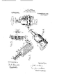
- Figure 1 is a front to rear vertical sectional view of a tvpewriting machine having my invention embodied therein, only so much of said machine being shown as is necessary" to illustrate the application of my invention thereto.
- Fig. 2 is a central sectional view through the retarding device.
- Fig. 3 is a rear elevation of said device and some of its connections.
- Fig. 4 is a ri ht-hand side elevation.
- Fig. 5 is a verticsil section through the carriage driving mechanism. Fi s. 1 and 5 are on a slightly reduced scale an the remaining figures are on .an enlarged scale.
- My invention 18 applicable or adaptable to typewriting machines generally but it is here shown applied to a Smith Premier No. 10 typewriter.
- This is a front strike machine having a main frame comprising side plates 1, a top plate 2 and a transverse back plate 3,the last being at the back of the'base of'the machine and secured at it's ends to the side plates 1.
- the paper carriage 4, having a platen 5 thereon, has grooved bars 6-which constitute rails or raceways for anti-friction rollers 7 which run also in moves in a stationary rail 8 mounted by standards on the top plate of the machine.
- the carriage is propelled by a'driving spring 9 connected at its inner end to a sleeve 10 and at its outer end to a sort of barrel or drum 11, said sleeve being mounted loosely and said drum bein mounted rigidly on a shaft 12, which is ournaled at its ends in a framework which comprises two vertical plates 13 and 14.
- the drum 11, during the ordinary travel of the carriage, remains stationary, but said drum is adjustable byturningit to vary the tension of the spring,- this adjustment being eflected by means of a thumb-piece on the rear end 6 of the shaft 12.
- the sleeve 10 which is journaled on the shaft 12, has a flange to which is riveted a large driving gear 15 that meshes with a toothed rack bar 16 mounted on the lower one of the carriage rails 6.
- Another large gear 17 is journaled on the sleeve 10 just at the rear of the gear 15 but is not. rigidly connected with said sleeve or gear.
- Said car 17 meshes with'the rack 16 and with a pmion 18 mounted with freedom to turn on a shaft 20 which is journaled at its ends in the plates 13 and 14.
- the rear end of the pinion 18 is formed with clutch teeth with which mesh the teeth of a companion clutch member 21 which is mounted on the shaft 20 with freedom to slide thereon but constrained to turn with the shaft.
- the clutch member 21 is normally held in the operative position shown in Fig. 1 by means of a spring but it can he slid toward the rear to disconnect the clutch members by means of an arm 22 that projects from a vertically disposed rocking member 23 into a peripheral gioovein the clutch member 21-
- the mem r 23 ispivoted at its uppei and lower ends respectively in brackets 2- and 25 projecting from the frame plate 14
- the shaft 20 i connected by a train of gears not shown, to an escapementwhich is no shown herein but which is shown in a prior application of Alexander T. Brown and also intie British patent to Brown No.
- the machine is equipped with a..'tebula-- tor which comprises a column stop bar 2 mounted on arms 27 depending from th carriage 4, to which said arms are pivoted by means of a cross shaft 28.
- the frame comprisingtliemc'k'bar 26, arms 27 and red 28, is normally held in the position shown 'by means of a spring 30, and it is arrested
- Column stops 32 are mounted on and a e adjustable along the rack bar 26 in the usual manner.
- universal bar 44 lies across the rear arms 36 of the tabulator key levers and is adapted to be moved upward when any of the key levers is operated.
- -Said universal bar is carried at the forward ends of arms 45, which at their rear ends are secured to a rock shaft 46 which is journaled in lugs 47 projecting from the back plate 3 of the stationary frame.
- the universal bar is normally held in its lower position by a spring 48.
- An arm 50 mounted on and depending from the rock shaft 46, is arranged to operate the lower arm of a lever 51 of the first order, said lever being fulcrumed at 52 in a bracket .of the plate 3.
- the upper end of the lever 51' lies in ,front of the arm 22 which engages the peripheral groove in the clutch member 21.
- My retarder comprises a receptacle which is here shown as a bottle-shaped barrel 53 having near the lower end thereof a long hub 54 which is loosely mounted on the shaft 46 so that the barrel 53 can turn with relation tosaid shaft.
- An arm 55 is mount-- ed on the shaft 46b the side of the hub 54: and is rigidly secured on said shaft by means of a set screw 56.
- Saidarm is 0011-; nested at its upper end by means of. a
- the barrel 53 is formed with an elongated neck 61 in which is journaled a shaft 62 having mounted at its outer end a bevel pinion 63 which normally stands in the position shown in Figs. 1 and 3 but which, when the barrel is turned upward by the rocking of the shaft 46, moves into mesh with the gear wheel 15 as shown in Fig. 5, so that said gear wheel rotates the pinion 63.
- the shaft 62 is formed witha reduced part 64, the outer end of which is threaded and the pinion 63 is screwed down on these threads until the elongated hub of said pinion is tight against the shoulder formed by the reduction in diameter of the shaft.
- the parts are secured in position
- the inner end 66 of the shaft 62 is enlarged and the bore of the neck 61 is correspondingly enlarged so that this enlarged end 66 actin in one direction, and the hub of the pinion 63 acting in the other, prevent endwise motion of the shaft 62.
- a wire 67, coiled into the helical or cork-screw shape shown in Fig. 2, is secured at its'upper end in the shaft 62, being inserted in a longitudinalbore in said shaft and bent ofl' into a transverse hole or bore 68 for the purpose of-causing the wire to turn with the shaft.
- This eork-screw-tlike wire occupies the enlarged part of the barrel or bottle 53 where it plays in a substance or mixture 70.
- This substance, mass .or mixture preferably consists of divided .solid material, this is to say, of solid particles or pieces of such character that the screw 67 can turn in the mass, but turns against a substantial resistance, so that excessive speed of the carriage is prevented. No doubt the precise character of this resistin -medium can be varied considerably. I ave used with success a mixture of small shot and granulated or powdered graphite, which is what is represented in the draw' I prefer, however, to use the graphite alone, as the shot have a tendency to become crushed out of shape. ItWlll of course, be understood that it is not essential that the screw or helix 67 be made in the precise form here shown.
- the bottom of the bottle or barrel. g is internally screw threaded and is closed by a screw plug 71.
- a screw plug 71 To prevent this plug'f'rom jarring loose, it 'is 'formed with a slot 72 sawed parallel with two flat surfaces of the plug, and a headed screw 73 passes loosely through one wall of the slot and is threaded into the other.
- a headed screw 73 By tightening this screw the threads of the plug can be clamped against those of the barrel so that any danger of the plug jarring loose is obviated, even though the fit of the plug in the barrel may be otherwise rather a free one.
- the plug 71 up or down the depth to which the screw is buried in the material 70, can be varied, and the resistance will also be varied, being greater when the plug is screwed up and more of the screw is in the resisting medium.
- an adjustable stop screw 74 is threaded into an ear 75 on the barrel 53 in such position that said screw is adapted to strike against the back plate 3 when the barrel is turned toward the rear by an 0 eration of the tabulator.
- the screw 74 can e adjusted in or out in order togive a proper intermeshing of the pinion 63 and geai l'fiand said screw can be secured in adjusted position by tigh ening a second screw 76 which is threaded into the opposite end of the same hole as the screw 74, so that when the screw 76 is tightened, it is tightened against the end of the screw 74 and both screws are locked against turning.
- a retarder of the character herein described has a much greater effect when it is turnin in one direction that it has when it is turnlng in the other direction. ⁇ Vhen the screw is turned in such a direction that it tends to force the shot and graphite toward the bottom of the barrel, the retarding efiect is much greater than when it'tends to elevate said shot-and graphite.
- This is of distinct advantage'because sometimes the carriage is moved toward the right by hand when a tabulator "key is depressed and the retarder is therefore in engagement with the wheel and geared to the carriage, and it is not desired at this time to ofl'er much if any resistance to the motion of the carriage.
- the barrel is not entirely filled with the material 70.
- the screw and the bottom of the barrel more relatively when the carriage travels, the mass 70 constituting an interposed element which, when the carriage moves in one direction, is pressed by the incline of the screw against said bottom of the barrel to increase the resistance in that direction.
- a retarder for the carriage of a typewriting machine comprising a.helix working in a mass of particles of solid material.
- a retarder for the carriage of a typewriting machine com rising a wire bent into a spiral form an working in a mass of particles of solid material.
- a 'retarder for the carriage of a typewriting machine comprising a helix working in graphite.
- a retarder for the carriage of a typewriting machine comprising a barrel-containing a mass of particles of solid material,
- a typewriting machine the combination of a carriage. a driving spring for said carriage. a rack on said carriage. a gear wheel for transmitting the power of said spring to said rack. a carriage retarder, one or more column stops on said carriage, a series of denominational stops consisting of bars arranged [0 be pushed upward into engagement with said stops, denominational key levers to which said bars are connected. a universal bar operated by the upward motion of said hey levers and denominational steps, a rock shaft on which said universal 'bar is mounted. and means operated by said rock shaft for throwing said retarder into and out of operative connection with said -gearwheel.
- a/carriage a driving spring for said carriage, a gear driven by said spring, cotiperating tabulator stops including column stops on the carriage and vertically movable denominational stops in the frame of the machine, a rocker operated by theoperation of one of said denominational stops, carriage releasing mechanism operated by said rocker, a rotary carriage retarder having a pinion operated by said gear, and means operated by said rocker for throwing said retarder into action when one of the tabulator stops is operated.
- a tvpewriting machine the combination of a carriage, a driving spring for said. carriage, a gear driven by said spring, cotiperatin tabulator stops, a rocker operated by t e o ration of one of said stops, carriage releasing mechanism operated by said rocker,.and a' rotary carriage retarder mounted on said rocker and having a pinion to be swung into engagement with said ear at the releasing movement of said roc err.
- a typewriting machine the combination of a' carriage, a spring for driving said carriage, one or more column stops on the carriage, a series of key-operated denominational stops, a rocking frame comprising a universal bar operated at the operation of any of said denominational stops, carriage releasing mechanism operated by said frame, and a carriage retarder mounted dirwtly on said rocking frame and moved by, an operation of said frame into operative connection with the carriage drivmechanism.”
- a typewriting machine the combination of .a carriage, a driving spring for said carriage, means ,7 including a toothed wheel-for connecting said spring with said carriage, one orimore column stops on the carriage, a series of key operated denominational stops, a rocker frame havinga universal; bar arranged to be operated at the operation of any of said denominational stops, carriage releasing mechanism operrated by said rocking frame, and a carriage retarder includin a barrel mounted directly on said roching frame and having a pinion movable by an operation of said frame to mesh with said toothed wheel.
- a typewriting machine the combination of a top late, a carriage mounted above said top p ate, a driving spring for said carriage mounted below said top plate, means including a wheel for transmltting the ower of said spring to said carriage, tabu ator mechanism including a series of key operated stops extending into the base of the machine, a universal rocking frame operated at the operation of any of said stops, and a carriage retarder mounted directly on said frame and movable thereby into operative connection with the lower part of said wheel.
- a typewriting machine the combination of a carriage,a toothed part arranged to move with said carriage, a tabulator having a rocking frame, a retarder having a pinion, a connection comprising a spring and a stop between said frame and said retarder whereby an operation of said tabulator moves said pinion into mesh with said toothed part, and a stop for arresting said 'retarder when the. pinion is in proper mesh,
- a retarder for the carriage of a typewriting machine comprising a helix, a stationary part, and an interposed element against which the helix works, the parts arranged so that when the helix turns in onedirection it presses said interposed element toward said stationary part and thus causes a comparatively great resistance, whereas when the helix turns in the other direction it meets a less resistance.
- a retarder for the carriage of a typewriting machine comprising two parts which move one with relation to the other during the travel of said carriage, andan interposed element, one of said parts being inclined to thedirection of such relative motion so that, when the carriage is moving in one direction, said interposed element is pressed by said incline toward the other of said parts to increase the resistance.
- a carriage In a typewriting machine, the combination of a carriage, a barrel containin a mass of particles of solid material an a helix and working in said materiah'gearing for connecting said helix with said carriage and a driving spring for said carriage, said 'helix arranged to force said material toward the bottom ofsaid barrel when the carriage moving in the direction in which it is moved by'said spring, .and toward the top (of the barrel when said carriage is movingin the oppositmdirection.
- a carriage retarder comprising a barrel containing a mass of particles of solid material, a device working in said material, and means adjustable to vary'the extent to which said device is buried in said material, inorder to vary the resistance.
- a carriage retarder comprising a device working in a mass of resisting material, and means adjustable to vary the extent to which said device is buried in said material, in order to vary the resistance.
- a carriage retarder comprising a barrel containing a mass of particles of solid material of less bulk than the capacity of the barrel, and a helix working in said material, said barrel 'having an adjustable bottom whereby the depth to which said helix is buried in said material can be varied;
- a carriage retarder comprising a barrel containing a mass of resisting material of less bulk than the capacity of t 1e barrel, a device working in said material, and means adjustable to contract or expand the barrel to vary the extent to which said device is buried in said material.
- a carriage retarder comprising a barrel containin a mass of resisting material of less bulk t an thefcapacity of the barrel, a device working in said material, and a plug adjustable up and down in said barrel to vary the extent to which said device is buried in said material.
Landscapes
- Transmission Devices (AREA)
Description
J. H. BARR. TYPE WRITING MACHINE. APPLICATION FILED JULY 5. 1910 1,016,061. Patented Jan. 30,1912.
2 SHEETS-BHEET 1.
WITNESSES INVENTDR:
Hls ATTDRNEY J. H. BARR. TYPE WRITING MACHINE. APPLIOATION FILED JULY5, 1910.
Patented Jam 30, 1912.
2 SHEETS-BHEET 2.
INVENTIJR= WITNEESEE:
HISATTDRNEV UNITED STATES PATENT OFFICE.
JOHN H. BARR, OF SYRACUSE, NE'l-V YORK, ASSIGNOR TO THE SMITH PREMIER TYPE- WRITER COMPANY, OF SYRACUSE, NEW YORK, A CORPORATION OF NEW YORK.
TYPE-WRITING MACHINE.
Specification of Letters Patent.
Patented Jan. 30, 1.912.
Application filed July 5, 1910. Serial No. 570.455.
To all whom it may concern:
Be it known that I, Jonx H. BARR, citizen of the United States, and resident of Syracuse. in the county of Onondaga and State of New York. have invented certain new and useful Improvements in Type \Vriting Machines. of which the following is a specification.
My invention relates to typewriting machines and it has for its principal object to provide improved means for controlling or retarding the motion of the carriage when said carriage is released from its step-bystep feed devices, as for example during tabulating operations.
My invention includes an improved retarder and also a novel means for or mode of connecting said retarder with the carriage of the typewriter.
My invention consists in certain features of construction and combinations and arrangements of parts, all of which will be fully set forth herein and particularly pointed out in'the claims.
In the accompanying drawings, Figure 1 is a front to rear vertical sectional view of a tvpewriting machine having my invention embodied therein, only so much of said machine being shown as is necessary" to illustrate the application of my invention thereto. Fig. 2 is a central sectional view through the retarding device. Fig. 3 is a rear elevation of said device and some of its connections. Fig. 4 is a ri ht-hand side elevation. Fig. 5 is a verticsil section through the carriage driving mechanism. Fi s. 1 and 5 are on a slightly reduced scale an the remaining figures are on .an enlarged scale.
My invention 18 applicable or adaptable to typewriting machines generally but it is here shown applied to a Smith Premier No. 10 typewriter. This is a front strike machine having a main frame comprising side plates 1, a top plate 2 and a transverse back plate 3,the last being at the back of the'base of'the machine and secured at it's ends to the side plates 1. The paper carriage 4, having a platen 5 thereon, has grooved bars 6-which constitute rails or raceways for anti-friction rollers 7 which run also in moves in a stationary rail 8 mounted by standards on the top plate of the machine. The carriage is propelled by a'driving spring 9 connected at its inner end to a sleeve 10 and at its outer end to a sort of barrel or drum 11, said sleeve being mounted loosely and said drum bein mounted rigidly on a shaft 12, which is ournaled at its ends in a framework which comprises two vertical plates 13 and 14. The drum 11, during the ordinary travel of the carriage, remains stationary, but said drum is adjustable byturningit to vary the tension of the spring,- this adjustment being eflected by means of a thumb-piece on the rear end 6 of the shaft 12. The sleeve 10, which is journaled on the shaft 12, has a flange to which is riveted a large driving gear 15 that meshes with a toothed rack bar 16 mounted on the lower one of the carriage rails 6. Another large gear 17 is journaled on the sleeve 10 just at the rear of the gear 15 but is not. rigidly connected with said sleeve or gear. Said car 17 meshes with'the rack 16 and with a pmion 18 mounted with freedom to turn on a shaft 20 which is journaled at its ends in the plates 13 and 14. The rear end of the pinion 18 is formed with clutch teeth with which mesh the teeth of a companion clutch member 21 which is mounted on the shaft 20 with freedom to slide thereon but constrained to turn with the shaft. The clutch member 21 is normally held in the operative position shown in Fig. 1 by means of a spring but it can he slid toward the rear to disconnect the clutch members by means of an arm 22 that projects from a vertically disposed rocking member 23 into a peripheral gioovein the clutch member 21- The mem r 23 ispivoted at its uppei and lower ends respectively in brackets 2- and 25 projecting from the frame plate 14 The shaft 20 i connected by a train of gears not shown, to an escapementwhich is no shown herein but which is shown in a prior application of Alexander T. Brown and also intie British patent to Brown No. 4810 O 190 The machine is equipped with a..'tebula-- tor which comprises a column stop bar 2 mounted on arms 27 depending from th carriage 4, to which said arms are pivoted by means of a cross shaft 28. The frame comprisingtliemc'k'bar 26, arms 27 and red 28, is normally held in the position shown 'by means of a spring 30, and it is arrested Column stops 32 are mounted on and a e adjustable along the rack bar 26 in the usual manner. These column stops are adapted to cooperate with a series of denominational stops 33 which at their upper ends are guided in a bracket 34 secured to the top plate 2, and said stop bars are at their lower endspivoted at 35 to the rear ends of a series of nested levers 36 which are pivoted at 37 to a cross bar 38 of the main frame. The levers 36 have forwardly directed arms 40, to the forward ends ofwhich are pivoted the ends of the stems 41 of tabulator keys 42,-said key stems at their upper ends passing through a guide 43 and the keys 42 being arranged in a row at the back of the printing key-board of the ma chine. I have not deemed it necessary to illustrate this tabulator in all its details as its precise construction forms no part of my present invention and-as tabulators of this character are well known in the art. The one shown in the drawings is substantially identical with that shown in the patent to Alexander T. Brown No. 939,587, dated No-' vember 9th, 1909. The construction is such that when one of'the keys 42 is depressed the corresponding one of the stop bars 33 is slid upward ,-into the path'of the column sto s 32.
universal bar 44 lies across the rear arms 36 of the tabulator key levers and is adapted to be moved upward when any of the key levers is operated. -Said universal bar is carried at the forward ends of arms 45, which at their rear ends are secured to a rock shaft 46 which is journaled in lugs 47 projecting from the back plate 3 of the stationary frame. The universal bar is normally held in its lower position by a spring 48.- An arm 50, mounted on and depending from the rock shaft 46, is arranged to operate the lower arm of a lever 51 of the first order, said lever being fulcrumed at 52 in a bracket .of the plate 3. The upper end of the lever 51' lies in ,front of the arm 22 which engages the peripheral groove in the clutch member 21. When any tabulator key is o erated the lever 51 is rocked, the upper en of said lever moving toward the rear of the machine and disconnecting the clutch members'fll and 18, and thus freeing the carriage from the escapement, all as set forth more in detail in the patent to Alexander T. Brown just above referred to.
My retarder comprises a receptacle which is here shown as a bottle-shaped barrel 53 having near the lower end thereof a long hub 54 which is loosely mounted on the shaft 46 so that the barrel 53 can turn with relation tosaid shaft. An arm 55 is mount-- ed on the shaft 46b the side of the hub 54: and is rigidly secured on said shaft by means of a set screw 56. Saidarm is 0011-; nested at its upper end by means of. a
still more rigidly by a lock nut 65.
The barrel 53 is formed with an elongated neck 61 in which is journaled a shaft 62 having mounted at its outer end a bevel pinion 63 which normally stands in the position shown in Figs. 1 and 3 but which, when the barrel is turned upward by the rocking of the shaft 46, moves into mesh with the gear wheel 15 as shown in Fig. 5, so that said gear wheel rotates the pinion 63. Outside of the neck 61 of the bottle or barrel 53, the shaft 62 is formed witha reduced part 64, the outer end of which is threaded and the pinion 63 is screwed down on these threads until the elongated hub of said pinion is tight against the shoulder formed by the reduction in diameter of the shaft. The parts are secured in position The inner end 66 of the shaft 62, is enlarged and the bore of the neck 61 is correspondingly enlarged so that this enlarged end 66 actin in one direction, and the hub of the pinion 63 acting in the other, prevent endwise motion of the shaft 62. A wire 67, coiled into the helical or cork-screw shape shown in Fig. 2, is secured at its'upper end in the shaft 62, being inserted in a longitudinalbore in said shaft and bent ofl' into a transverse hole or bore 68 for the purpose of-causing the wire to turn with the shaft. This eork-screw-tlike wire occupies the enlarged part of the barrel or bottle 53 where it plays in a substance or mixture 70. This substance, mass .or mixture preferably consists of divided .solid material, this is to say, of solid particles or pieces of such character that the screw 67 can turn in the mass, but turns against a substantial resistance, so that excessive speed of the carriage is prevented. No doubt the precise character of this resistin -medium can be varied considerably. I ave used with success a mixture of small shot and granulated or powdered graphite, which is what is represented in the draw' I prefer, however, to use the graphite alone, as the shot have a tendency to become crushed out of shape. ItWlll of course, be understood that it is not essential that the screw or helix 67 be made in the precise form here shown.
The bottom of the bottle or barrel. g is internally screw threaded and is closed by a screw plug 71. To prevent this plug'f'rom jarring loose, it 'is 'formed with a slot 72 sawed parallel with two flat surfaces of the plug, and a headed screw 73 passes loosely through one wall of the slot and is threaded into the other. By tightening this screw the threads of the plug can be clamped against those of the barrel so that any danger of the plug jarring loose is obviated, even though the fit of the plug in the barrel may be otherwise rather a free one. By screwing the plug 71 up or down, the depth to which the screw is buried in the material 70, can be varied, and the resistance will also be varied, being greater when the plug is screwed up and more of the screw is in the resisting medium.
In order to limit the motion of the retarder and of the pinion 63 into engagement with the gear 15, an adjustable stop screw 74 is threaded into an ear 75 on the barrel 53 in such position that said screw is adapted to strike against the back plate 3 when the barrel is turned toward the rear by an 0 eration of the tabulator. The screw 74 can e adjusted in or out in order togive a proper intermeshing of the pinion 63 and geai l'fiand said screw can be secured in adjusted position by tigh ening a second screw 76 which is threaded into the opposite end of the same hole as the screw 74, so that when the screw 76 is tightened, it is tightened against the end of the screw 74 and both screws are locked against turning.
A retarder of the character herein described has a much greater effect when it is turnin in one direction that it has when it is turnlng in the other direction. \Vhen the screw is turned in such a direction that it tends to force the shot and graphite toward the bottom of the barrel, the retarding efiect is much greater than when it'tends to elevate said shot-and graphite. This is of distinct advantage'because sometimes the carriage is moved toward the right by hand when a tabulator "key is depressed and the retarder is therefore in engagement with the wheel and geared to the carriage, and it is not desired at this time to ofl'er much if any resistance to the motion of the carriage. I accordingly wind the spiral 67 in such a direction that when the, carriage is moving toward the left the spiral tends to force the shot and graphite downward; and when the carriage is moving toward the right it tends to elevate those things, so that I get .a
reater retarding effect when the carriage 1s moving under the impulse of the spring than I do when itis beingmoved in the opposite direction by hand. Iii-the Smith Premier No. 10 machine-,this retarder is used in connection witha 'tabiila'tor having the reverse tabulating -ieatnre described -.in the atent to Alexander T. Brown; N; 937,414,. dated October *19, 1909,'and in this connec-'-' resistance in one direction than in the other, is of marked advantage.
The material tends to fall by gravity to the bottomof the barrel, and when the screw is turning in a direction to press it down, said material is more tightly compressed by said screw; whereas said screw when turning in the opposite direction. plows and loosens up the material, which, therefore. otters comparatively little resistance. Preferably the barrel is not entirely filled with the material 70. The screw and the bottom of the barrel more relatively when the carriage travels, the mass 70 constituting an interposed element which, when the carriage moves in one direction, is pressed by the incline of the screw against said bottom of the barrel to increase the resistance in that direction.
Various changes can be made in the details of construction and arrangement without departing from my invention.
What I claim as new and desire to secure by Letters Patent, is
1. A retarder for the carriage of a typewriting machine, comprising a.helix working in a mass of particles of solid material.
2. A retarder for the carriage of a typewriting machine, com rising a wire bent into a spiral form an working in a mass of particles of solid material.
3. A 'retarder for the carriage of a typewriting machine, comprising a helix working in graphite.
4. A retarder for the carriage of a typewriting machine. comprising a barrel-containing a mass of particles of solid material,
'and a screw working in said material in a direction to force said material toward the bottom of the barrel.
5. In a typewriting machine. the combination of a carriage. a driving spring for said carriage. a rack on said carriage. a gear wheel for transmitting the power of said spring to said rack. a carriage retarder, one or more column stops on said carriage, a series of denominational stops consisting of bars arranged [0 be pushed upward into engagement with said stops, denominational key levers to which said bars are connected. a universal bar operated by the upward motion of said hey levers and denominational steps, a rock shaft on which said universal 'bar is mounted. and means operated by said rock shaft for throwing said retarder into and out of operative connection with said -gearwheel.
6. In a typewriting machine. the combinaticn of a carriage, a driving spring connected withlsaid carriage, a column stop upon the carriage, a :set 'of key-operated dencminational-stops,-:a rocker arran ed' to be" eperated atrflie operation- 0f any '0' said denominational" stops,- carriage releasing. mechanism connected to said rocker, a gear rotated by said s ring, a retarder having a pinion operated y said gear, and means whereby said rocker throws said retarder into and out of action:
-7. In a typewriting machine, the combination of a/carriage, a driving spring for said carriage, a gear driven by said spring, cotiperating tabulator stops including column stops on the carriage and vertically movable denominational stops in the frame of the machine, a rocker operated by theoperation of one of said denominational stops, carriage releasing mechanism operated by said rocker, a rotary carriage retarder having a pinion operated by said gear, and means operated by said rocker for throwing said retarder into action when one of the tabulator stops is operated.
8. In a typewriting machine, the combination of a carriage, a driving spring connected with said carriage, a column stop upon the carriage, a set of key-operated denominational stops, a rocker arranged to be operated at the operation of any of said denominational stops, carriage releasing mechanism connected to said. rocker, a pinion =i1pon' said rocker and turning upon an transverse to the rocker, a wear rotated said sprin and normally disconnected from said pinlon, the latter being mounted so that the carriage'releasing movement of the rocker throws it into mesh with the gear, and a retarding device operated by said" inion.
n a tvpewriting machine. the combination of a carriage, a driving spring for said. carriage, a gear driven by said spring, cotiperatin tabulator stops, a rocker operated by t e o ration of one of said stops, carriage releasing mechanism operated by said rocker,.and a' rotary carriage retarder mounted on said rocker and having a pinion to be swung into engagement with said ear at the releasing movement of said roc err.
10. In a typewriting machine, the combination ofa' carriage, a spring for driving said carriage, one or more column stops on the carriage, a series of key-operated denominational stops, a rocking frame comprising a universal bar operated at the operation of any of said denominational stops, carriage releasing mechanism operated by said frame, and a carriage retarder mounted dirwtly on said rocking frame and moved by, an operation of said frame into operative connection with the carriage drivmechanism."
11. In a typewriting machine, the combination of .a carriage, a driving spring for said carriage, means ,7 including a toothed wheel-for connecting said spring with said carriage, one orimore column stops on the carriage, a series of key operated denominational stops, a rocker frame havinga universal; bar arranged to be operated at the operation of any of said denominational stops, carriage releasing mechanism operrated by said rocking frame, and a carriage retarder includin a barrel mounted directly on said roching frame and having a pinion movable by an operation of said frame to mesh with said toothed wheel.
12. In a typewriting machine, the combination of a top late, a carriage mounted above said top p ate, a driving spring for said carriage mounted below said top plate, means including a wheel for transmltting the ower of said spring to said carriage, tabu ator mechanism including a series of key operated stops extending into the base of the machine, a universal rocking frame operated at the operation of any of said stops, and a carriage retarder mounted directly on said frame and movable thereby into operative connection with the lower part of said wheel.
13. In a typewriting machine, the combination of a carriage,a toothed part arranged to move with said carriage, a tabulator having a rocking frame, a retarder having a pinion, a connection comprising a spring and a stop between said frame and said retarder whereby an operation of said tabulator moves said pinion into mesh with said toothed part, and a stop for arresting said 'retarder when the. pinion is in proper mesh,
said spring permitting further motion of said rocking frame.
14. A retarder for the carriage of a typewriting machine, comprising a helix, a stationary part, and an interposed element against which the helix works, the parts arranged so that when the helix turns in onedirection it presses said interposed element toward said stationary part and thus causes a comparatively great resistance, whereas when the helix turns in the other direction it meets a less resistance.
15. A retarder for the carriage of a typewriting machine, comprising two parts which move one with relation to the other during the travel of said carriage, andan interposed element, one of said parts being inclined to thedirection of such relative motion so that, when the carriage is moving in one direction, said interposed element is pressed by said incline toward the other of said parts to increase the resistance.
16. In a typewriting machine, the combination of a carriage, a barrel containin a mass of particles of solid material an a helix and working in said materiah'gearing for connecting said helix with said carriage and a driving spring for said carriage, said 'helix arranged to force said material toward the bottom ofsaid barrel when the carriage moving in the direction in which it is moved by'said spring, .and toward the top (of the barrel when said carriage is movingin the oppositmdirection.
17. In a typewriting machine, a carriage retarder comprising a barrel containing a mass of particles of solid material, a device working in said material, and means adjustable to vary'the extent to which said device is buried in said material, inorder to vary the resistance.
18. In a typewriting machine, a carriage retarder comprising a device working in a mass of resisting material, and means adjustable to vary the extent to which said device is buried in said material, in order to vary the resistance.
19. In a typewriting machine, a carriage retarder comprising a barrel containing a mass of particles of solid material of less bulk than the capacity of the barrel, and a helix working in said material, said barrel 'having an adjustable bottom whereby the depth to which said helix is buried in said material can be varied;
20. In a typewriting machine, a carriage retarder comprising a barrel containing a mass of resisting material of less bulk than the capacity of t 1e barrel, a device working in said material, and means adjustable to contract or expand the barrel to vary the extent to which said device is buried in said material.
21. In a typewriting machine, a carriage retarder comprising a barrel containin a mass of resisting material of less bulk t an thefcapacity of the barrel, a device working in said material, and a plug adjustable up and down in said barrel to vary the extent to which said device is buried in said material.
Signed at Syracuse, in the count of Onondaga, and State of New York, this 1st day of July, A. D. 1910.
JOHN H. BARR.
Witnesses:
E. E. CORY, I. L. MARTDT.
Priority Applications (1)
| Application Number | Priority Date | Filing Date | Title |
|---|---|---|---|
| US57045510A US1016061A (en) | 1910-07-05 | 1910-07-05 | Type-writing machine. |
Applications Claiming Priority (1)
| Application Number | Priority Date | Filing Date | Title |
|---|---|---|---|
| US57045510A US1016061A (en) | 1910-07-05 | 1910-07-05 | Type-writing machine. |
Publications (1)
| Publication Number | Publication Date |
|---|---|
| US1016061A true US1016061A (en) | 1912-01-30 |
Family
ID=3084364
Family Applications (1)
| Application Number | Title | Priority Date | Filing Date |
|---|---|---|---|
| US57045510A Expired - Lifetime US1016061A (en) | 1910-07-05 | 1910-07-05 | Type-writing machine. |
Country Status (1)
| Country | Link |
|---|---|
| US (1) | US1016061A (en) |
-
1910
- 1910-07-05 US US57045510A patent/US1016061A/en not_active Expired - Lifetime
Similar Documents
| Publication | Publication Date | Title |
|---|---|---|
| US1016061A (en) | Type-writing machine. | |
| US2870897A (en) | Electrically operated text writing device for bookkeeping machines | |
| US2728437A (en) | Back spacing mechanism for typewriters or like machines | |
| US1110346A (en) | Type-writing machine. | |
| US1121971A (en) | Type-writing machine. | |
| US1567590A (en) | Typewriting and like machine | |
| US1107530A (en) | Carriage-return mechanism. | |
| US1090219A (en) | Type-writing machine. | |
| US784380A (en) | Type-writing machine. | |
| US918354A (en) | Writing-machine. | |
| US1077005A (en) | Type-writing machine. | |
| US1163761A (en) | Type-writing machine. | |
| US1145832A (en) | Escapement mechanism for type-writers, &c. | |
| US1594436A (en) | Line-spacing mechanism for typewriting machines | |
| US931688A (en) | Type-writing machine. | |
| US779407A (en) | Type-writing machine. | |
| US2573508A (en) | Fugitive one mechanism for typewriting and accounting machines | |
| US889102A (en) | Type-writing machine. | |
| US907730A (en) | Type-writing machine. | |
| US1188873A (en) | Type-writing machine. | |
| US1271762A (en) | Calculating-machine. | |
| US1274365A (en) | Combined type-writing and computing machine. | |
| US423900A (en) | Type-writing machine | |
| US1029101A (en) | Type-writing machine. | |
| US977582A (en) | Adding-machine. |