US10153486B2 - Positive electrode material, positive electrode for non-aqueous electrolyte secondary battery, and non-aqueous electrolyte secondary battery - Google Patents
Positive electrode material, positive electrode for non-aqueous electrolyte secondary battery, and non-aqueous electrolyte secondary battery Download PDFInfo
- Publication number
- US10153486B2 US10153486B2 US15/066,057 US201615066057A US10153486B2 US 10153486 B2 US10153486 B2 US 10153486B2 US 201615066057 A US201615066057 A US 201615066057A US 10153486 B2 US10153486 B2 US 10153486B2
- Authority
- US
- United States
- Prior art keywords
- positive electrode
- electrode material
- satisfies
- equation
- layer
- Prior art date
- Legal status (The legal status is an assumption and is not a legal conclusion. Google has not performed a legal analysis and makes no representation as to the accuracy of the status listed.)
- Active, expires
Links
- 239000007774 positive electrode material Substances 0.000 title claims abstract description 144
- 239000011255 nonaqueous electrolyte Substances 0.000 title claims description 35
- 239000000126 substance Substances 0.000 claims abstract description 21
- 229910052733 gallium Inorganic materials 0.000 claims abstract description 5
- QVGXLLKOCUKJST-UHFFFAOYSA-N atomic oxygen Chemical compound [O] QVGXLLKOCUKJST-UHFFFAOYSA-N 0.000 claims description 42
- 239000001301 oxygen Substances 0.000 claims description 42
- 229910052760 oxygen Inorganic materials 0.000 claims description 42
- 238000010521 absorption reaction Methods 0.000 claims description 25
- 238000004458 analytical method Methods 0.000 claims description 13
- 238000000862 absorption spectrum Methods 0.000 claims description 5
- 229910052718 tin Inorganic materials 0.000 abstract description 7
- 229910052732 germanium Inorganic materials 0.000 abstract description 6
- 229910052787 antimony Inorganic materials 0.000 abstract description 4
- PXHVJJICTQNCMI-UHFFFAOYSA-N nickel Substances [Ni] PXHVJJICTQNCMI-UHFFFAOYSA-N 0.000 description 46
- 239000000203 mixture Substances 0.000 description 29
- 229910001416 lithium ion Inorganic materials 0.000 description 27
- HBBGRARXTFLTSG-UHFFFAOYSA-N Lithium ion Chemical compound [Li+] HBBGRARXTFLTSG-UHFFFAOYSA-N 0.000 description 24
- 239000000843 powder Substances 0.000 description 24
- 150000001875 compounds Chemical class 0.000 description 16
- 239000012071 phase Substances 0.000 description 16
- 230000000694 effects Effects 0.000 description 14
- 239000013078 crystal Substances 0.000 description 13
- 229910052751 metal Inorganic materials 0.000 description 13
- 239000002184 metal Substances 0.000 description 13
- 238000003795 desorption Methods 0.000 description 11
- 238000000634 powder X-ray diffraction Methods 0.000 description 10
- 238000005259 measurement Methods 0.000 description 9
- 238000000034 method Methods 0.000 description 9
- 239000007773 negative electrode material Substances 0.000 description 9
- -1 diethyltriamine Chemical compound 0.000 description 8
- 230000006872 improvement Effects 0.000 description 8
- 239000003960 organic solvent Substances 0.000 description 8
- 239000003115 supporting electrolyte Substances 0.000 description 8
- 239000011230 binding agent Substances 0.000 description 7
- 230000000052 comparative effect Effects 0.000 description 7
- 239000010936 titanium Substances 0.000 description 7
- 229910052723 transition metal Inorganic materials 0.000 description 7
- SECXISVLQFMRJM-UHFFFAOYSA-N N-Methylpyrrolidone Chemical compound CN1CCCC1=O SECXISVLQFMRJM-UHFFFAOYSA-N 0.000 description 6
- 239000004020 conductor Substances 0.000 description 6
- 238000005342 ion exchange Methods 0.000 description 6
- 229910052744 lithium Inorganic materials 0.000 description 6
- 239000000463 material Substances 0.000 description 6
- 238000002156 mixing Methods 0.000 description 6
- 235000002639 sodium chloride Nutrition 0.000 description 6
- 150000003624 transition metals Chemical class 0.000 description 6
- 239000007864 aqueous solution Substances 0.000 description 5
- 230000006378 damage Effects 0.000 description 5
- 150000003839 salts Chemical class 0.000 description 5
- 239000007858 starting material Substances 0.000 description 5
- OKTJSMMVPCPJKN-UHFFFAOYSA-N Carbon Chemical compound [C] OKTJSMMVPCPJKN-UHFFFAOYSA-N 0.000 description 4
- 229910008740 Li2NiSnO4 Inorganic materials 0.000 description 4
- 229910018553 Ni—O Inorganic materials 0.000 description 4
- 239000002033 PVDF binder Substances 0.000 description 4
- 229910020923 Sn-O Inorganic materials 0.000 description 4
- 239000011149 active material Substances 0.000 description 4
- 239000003575 carbonaceous material Substances 0.000 description 4
- 238000011156 evaluation Methods 0.000 description 4
- 238000004519 manufacturing process Methods 0.000 description 4
- 229910052759 nickel Inorganic materials 0.000 description 4
- 229920002981 polyvinylidene fluoride Polymers 0.000 description 4
- 230000009467 reduction Effects 0.000 description 4
- 239000002904 solvent Substances 0.000 description 4
- 238000001228 spectrum Methods 0.000 description 4
- 238000012360 testing method Methods 0.000 description 4
- ZWEHNKRNPOVVGH-UHFFFAOYSA-N 2-Butanone Chemical compound CCC(C)=O ZWEHNKRNPOVVGH-UHFFFAOYSA-N 0.000 description 3
- OIFBSDVPJOWBCH-UHFFFAOYSA-N Diethyl carbonate Chemical compound CCOC(=O)OCC OIFBSDVPJOWBCH-UHFFFAOYSA-N 0.000 description 3
- KMTRUDSVKNLOMY-UHFFFAOYSA-N Ethylene carbonate Chemical compound O=C1OCCO1 KMTRUDSVKNLOMY-UHFFFAOYSA-N 0.000 description 3
- 229910005931 Li1.05NiO2 Inorganic materials 0.000 description 3
- 229910011867 Li2.1NiMn0.67Ge0.33O4 Inorganic materials 0.000 description 3
- 229910001290 LiPF6 Inorganic materials 0.000 description 3
- WHXSMMKQMYFTQS-UHFFFAOYSA-N Lithium Chemical compound [Li] WHXSMMKQMYFTQS-UHFFFAOYSA-N 0.000 description 3
- ZMXDDKWLCZADIW-UHFFFAOYSA-N N,N-Dimethylformamide Chemical compound CN(C)C=O ZMXDDKWLCZADIW-UHFFFAOYSA-N 0.000 description 3
- 238000004998 X ray absorption near edge structure spectroscopy Methods 0.000 description 3
- 238000002835 absorbance Methods 0.000 description 3
- 239000006230 acetylene black Substances 0.000 description 3
- 229910052782 aluminium Inorganic materials 0.000 description 3
- 230000001174 ascending effect Effects 0.000 description 3
- 239000002131 composite material Substances 0.000 description 3
- 238000007599 discharging Methods 0.000 description 3
- 230000002708 enhancing effect Effects 0.000 description 3
- 239000011888 foil Substances 0.000 description 3
- 229910052748 manganese Inorganic materials 0.000 description 3
- 125000004430 oxygen atom Chemical group O* 0.000 description 3
- 229920001343 polytetrafluoroethylene Polymers 0.000 description 3
- 239000004810 polytetrafluoroethylene Substances 0.000 description 3
- 238000001308 synthesis method Methods 0.000 description 3
- XTHFKEDIFFGKHM-UHFFFAOYSA-N Dimethoxyethane Chemical compound COCCOC XTHFKEDIFFGKHM-UHFFFAOYSA-N 0.000 description 2
- 229910012065 Li2.1Ni0.88Co0.22Mn0.44Ge0.44O4 Inorganic materials 0.000 description 2
- 229910011891 Li2.1NiMn0.67Sn0.33O4 Inorganic materials 0.000 description 2
- 229910010468 Li2Ni0.88Co0.22Mn0.44Ge0.44O4 Inorganic materials 0.000 description 2
- 229910008697 Li2NiGeO4 Inorganic materials 0.000 description 2
- 229910008703 Li2NiMn0.67Ge0.33O4 Inorganic materials 0.000 description 2
- 229910008704 Li2NiMn0.67Sn0.33O4 Inorganic materials 0.000 description 2
- 229910013258 LiNiMnTiO2 Inorganic materials 0.000 description 2
- BAPJBEWLBFYGME-UHFFFAOYSA-N Methyl acrylate Chemical compound COC(=O)C=C BAPJBEWLBFYGME-UHFFFAOYSA-N 0.000 description 2
- 229910018663 Mn O Inorganic materials 0.000 description 2
- 229910003176 Mn-O Inorganic materials 0.000 description 2
- 229910004621 Na2Ni0.88Co0.22Mn0.44Ge0.44O4 Inorganic materials 0.000 description 2
- 229910004641 Na2NiMn0.67Ge0.33O4 Inorganic materials 0.000 description 2
- 229910004638 Na2NiMn0.67Sn0.33O4 Inorganic materials 0.000 description 2
- 239000004372 Polyvinyl alcohol Substances 0.000 description 2
- FAPWRFPIFSIZLT-UHFFFAOYSA-M Sodium chloride Chemical group [Na+].[Cl-] FAPWRFPIFSIZLT-UHFFFAOYSA-M 0.000 description 2
- WYURNTSHIVDZCO-UHFFFAOYSA-N Tetrahydrofuran Chemical compound C1CCOC1 WYURNTSHIVDZCO-UHFFFAOYSA-N 0.000 description 2
- 239000000956 alloy Substances 0.000 description 2
- XAGFODPZIPBFFR-UHFFFAOYSA-N aluminium Chemical compound [Al] XAGFODPZIPBFFR-UHFFFAOYSA-N 0.000 description 2
- 125000004429 atom Chemical group 0.000 description 2
- 239000006229 carbon black Substances 0.000 description 2
- 150000004649 carbonic acid derivatives Chemical class 0.000 description 2
- 229920001577 copolymer Polymers 0.000 description 2
- JHIVVAPYMSGYDF-UHFFFAOYSA-N cyclohexanone Chemical compound O=C1CCCCC1 JHIVVAPYMSGYDF-UHFFFAOYSA-N 0.000 description 2
- IEJIGPNLZYLLBP-UHFFFAOYSA-N dimethyl carbonate Chemical compound COC(=O)OC IEJIGPNLZYLLBP-UHFFFAOYSA-N 0.000 description 2
- 238000001035 drying Methods 0.000 description 2
- 150000002170 ethers Chemical class 0.000 description 2
- 239000010419 fine particle Substances 0.000 description 2
- 229920001973 fluoroelastomer Polymers 0.000 description 2
- 229910052500 inorganic mineral Inorganic materials 0.000 description 2
- 239000003273 ketjen black Substances 0.000 description 2
- KWGKDLIKAYFUFQ-UHFFFAOYSA-M lithium chloride Chemical compound [Li+].[Cl-] KWGKDLIKAYFUFQ-UHFFFAOYSA-M 0.000 description 2
- IIPYXGDZVMZOAP-UHFFFAOYSA-N lithium nitrate Chemical compound [Li+].[O-][N+]([O-])=O IIPYXGDZVMZOAP-UHFFFAOYSA-N 0.000 description 2
- 230000007257 malfunction Effects 0.000 description 2
- 239000011707 mineral Substances 0.000 description 2
- 235000010755 mineral Nutrition 0.000 description 2
- 239000012046 mixed solvent Substances 0.000 description 2
- 238000002253 near-edge X-ray absorption fine structure spectrum Methods 0.000 description 2
- 229920002451 polyvinyl alcohol Polymers 0.000 description 2
- 238000012545 processing Methods 0.000 description 2
- 238000011076 safety test Methods 0.000 description 2
- 238000007789 sealing Methods 0.000 description 2
- 239000011734 sodium Substances 0.000 description 2
- 230000000087 stabilizing effect Effects 0.000 description 2
- 229920003048 styrene butadiene rubber Polymers 0.000 description 2
- 229910052719 titanium Inorganic materials 0.000 description 2
- XLYOFNOQVPJJNP-UHFFFAOYSA-N water Substances O XLYOFNOQVPJJNP-UHFFFAOYSA-N 0.000 description 2
- DTCCVIYSGXONHU-CJHDCQNGSA-N (z)-2-(2-phenylethenyl)but-2-enedioic acid Chemical compound OC(=O)\C=C(C(O)=O)\C=CC1=CC=CC=C1 DTCCVIYSGXONHU-CJHDCQNGSA-N 0.000 description 1
- VAYTZRYEBVHVLE-UHFFFAOYSA-N 1,3-dioxol-2-one Chemical compound O=C1OC=CO1 VAYTZRYEBVHVLE-UHFFFAOYSA-N 0.000 description 1
- 229910017942 Ag—Ge Inorganic materials 0.000 description 1
- 229910017980 Ag—Sn Inorganic materials 0.000 description 1
- 229920002134 Carboxymethyl cellulose Polymers 0.000 description 1
- RYGMFSIKBFXOCR-UHFFFAOYSA-N Copper Chemical compound [Cu] RYGMFSIKBFXOCR-UHFFFAOYSA-N 0.000 description 1
- 229910017755 Cu-Sn Inorganic materials 0.000 description 1
- 229910017927 Cu—Sn Inorganic materials 0.000 description 1
- MYMOFIZGZYHOMD-UHFFFAOYSA-N Dioxygen Chemical compound O=O MYMOFIZGZYHOMD-UHFFFAOYSA-N 0.000 description 1
- 229920002943 EPDM rubber Polymers 0.000 description 1
- IAYPIBMASNFSPL-UHFFFAOYSA-N Ethylene oxide Chemical compound C1CO1 IAYPIBMASNFSPL-UHFFFAOYSA-N 0.000 description 1
- 229910010158 Li2MO3 Inorganic materials 0.000 description 1
- 229910010364 Li2MSiO4 Inorganic materials 0.000 description 1
- 229910010142 Li2MnSiO4 Inorganic materials 0.000 description 1
- 229910032387 LiCoO2 Inorganic materials 0.000 description 1
- 229910014639 LiMnMO2 Inorganic materials 0.000 description 1
- 229910013385 LiN(SO2C2F5)2 Inorganic materials 0.000 description 1
- 229910013392 LiN(SO2CF3)(SO2C4F9) Inorganic materials 0.000 description 1
- 229910013406 LiN(SO2CF3)2 Inorganic materials 0.000 description 1
- 229910012756 LiNi0.5Mn0.5−xTixO2 Inorganic materials 0.000 description 1
- 229910013288 LiNiMO2 Inorganic materials 0.000 description 1
- 229910013240 LiNiMnMO2 Inorganic materials 0.000 description 1
- 229910016735 LixCoMO2 Inorganic materials 0.000 description 1
- 229910015609 LixMnMO4 Inorganic materials 0.000 description 1
- FXHOOIRPVKKKFG-UHFFFAOYSA-N N,N-Dimethylacetamide Chemical compound CN(C)C(C)=O FXHOOIRPVKKKFG-UHFFFAOYSA-N 0.000 description 1
- 229910004644 Na2NiSnO4 Inorganic materials 0.000 description 1
- 229910018100 Ni-Sn Inorganic materials 0.000 description 1
- 229920000459 Nitrile rubber Polymers 0.000 description 1
- 229910018532 Ni—Sn Inorganic materials 0.000 description 1
- 239000004698 Polyethylene Substances 0.000 description 1
- 239000004743 Polypropylene Substances 0.000 description 1
- XBDQKXXYIPTUBI-UHFFFAOYSA-M Propionate Chemical compound CCC([O-])=O XBDQKXXYIPTUBI-UHFFFAOYSA-M 0.000 description 1
- 229910020935 Sn-Sb Inorganic materials 0.000 description 1
- 229910008757 Sn—Sb Inorganic materials 0.000 description 1
- 229910004339 Ti-Si Inorganic materials 0.000 description 1
- RTAQQCXQSZGOHL-UHFFFAOYSA-N Titanium Chemical compound [Ti] RTAQQCXQSZGOHL-UHFFFAOYSA-N 0.000 description 1
- 229910010978 Ti—Si Inorganic materials 0.000 description 1
- 238000002441 X-ray diffraction Methods 0.000 description 1
- KXKVLQRXCPHEJC-UHFFFAOYSA-N acetic acid trimethyl ester Natural products COC(C)=O KXKVLQRXCPHEJC-UHFFFAOYSA-N 0.000 description 1
- 229920000800 acrylic rubber Polymers 0.000 description 1
- 230000004913 activation Effects 0.000 description 1
- 229910045601 alloy Inorganic materials 0.000 description 1
- 229910003481 amorphous carbon Inorganic materials 0.000 description 1
- 239000003125 aqueous solvent Substances 0.000 description 1
- 230000015572 biosynthetic process Effects 0.000 description 1
- 238000010504 bond cleavage reaction Methods 0.000 description 1
- 229910052796 boron Inorganic materials 0.000 description 1
- 229910052799 carbon Inorganic materials 0.000 description 1
- 239000002134 carbon nanofiber Substances 0.000 description 1
- 239000010406 cathode material Substances 0.000 description 1
- 230000008859 change Effects 0.000 description 1
- 238000006243 chemical reaction Methods 0.000 description 1
- 229910052804 chromium Inorganic materials 0.000 description 1
- 238000000975 co-precipitation Methods 0.000 description 1
- 229910017052 cobalt Inorganic materials 0.000 description 1
- 239000010941 cobalt Substances 0.000 description 1
- GUTLYIVDDKVIGB-UHFFFAOYSA-N cobalt atom Chemical compound [Co] GUTLYIVDDKVIGB-UHFFFAOYSA-N 0.000 description 1
- 229920001940 conductive polymer Polymers 0.000 description 1
- 238000010276 construction Methods 0.000 description 1
- 229910052802 copper Inorganic materials 0.000 description 1
- 239000010949 copper Substances 0.000 description 1
- KUNSUQLRTQLHQQ-UHFFFAOYSA-N copper tin Chemical compound [Cu].[Sn] KUNSUQLRTQLHQQ-UHFFFAOYSA-N 0.000 description 1
- 230000006866 deterioration Effects 0.000 description 1
- 229910001882 dioxygen Inorganic materials 0.000 description 1
- 239000002270 dispersing agent Substances 0.000 description 1
- 238000010292 electrical insulation Methods 0.000 description 1
- 239000008151 electrolyte solution Substances 0.000 description 1
- 239000000839 emulsion Substances 0.000 description 1
- JBTWLSYIZRCDFO-UHFFFAOYSA-N ethyl methyl carbonate Chemical compound CCOC(=O)OC JBTWLSYIZRCDFO-UHFFFAOYSA-N 0.000 description 1
- 230000002349 favourable effect Effects 0.000 description 1
- 239000010439 graphite Substances 0.000 description 1
- 229910002804 graphite Inorganic materials 0.000 description 1
- 150000008282 halocarbons Chemical class 0.000 description 1
- 238000010438 heat treatment Methods 0.000 description 1
- 239000001307 helium Substances 0.000 description 1
- 229910052734 helium Inorganic materials 0.000 description 1
- SWQJXJOGLNCZEY-UHFFFAOYSA-N helium atom Chemical compound [He] SWQJXJOGLNCZEY-UHFFFAOYSA-N 0.000 description 1
- 238000002354 inductively-coupled plasma atomic emission spectroscopy Methods 0.000 description 1
- 150000002500 ions Chemical class 0.000 description 1
- 229910052742 iron Inorganic materials 0.000 description 1
- 150000002576 ketones Chemical class 0.000 description 1
- 150000002596 lactones Chemical class 0.000 description 1
- 150000002641 lithium Chemical class 0.000 description 1
- 229910001540 lithium hexafluoroarsenate(V) Inorganic materials 0.000 description 1
- MHCFAGZWMAWTNR-UHFFFAOYSA-M lithium perchlorate Chemical compound [Li+].[O-]Cl(=O)(=O)=O MHCFAGZWMAWTNR-UHFFFAOYSA-M 0.000 description 1
- 229910001486 lithium perchlorate Inorganic materials 0.000 description 1
- 229910001496 lithium tetrafluoroborate Inorganic materials 0.000 description 1
- QSZMZKBZAYQGRS-UHFFFAOYSA-N lithium;bis(trifluoromethylsulfonyl)azanide Chemical compound [Li+].FC(F)(F)S(=O)(=O)[N-]S(=O)(=O)C(F)(F)F QSZMZKBZAYQGRS-UHFFFAOYSA-N 0.000 description 1
- MCVFFRWZNYZUIJ-UHFFFAOYSA-M lithium;trifluoromethanesulfonate Chemical compound [Li+].[O-]S(=O)(=O)C(F)(F)F MCVFFRWZNYZUIJ-UHFFFAOYSA-M 0.000 description 1
- 150000002739 metals Chemical class 0.000 description 1
- VNWKTOKETHGBQD-UHFFFAOYSA-N methane Chemical compound C VNWKTOKETHGBQD-UHFFFAOYSA-N 0.000 description 1
- 239000011259 mixed solution Substances 0.000 description 1
- 230000004048 modification Effects 0.000 description 1
- 238000012986 modification Methods 0.000 description 1
- SWVGZFQJXVPIKM-UHFFFAOYSA-N n,n-bis(methylamino)propan-1-amine Chemical compound CCCN(NC)NC SWVGZFQJXVPIKM-UHFFFAOYSA-N 0.000 description 1
- 229910021382 natural graphite Inorganic materials 0.000 description 1
- 239000011331 needle coke Substances 0.000 description 1
- 229910001317 nickel manganese cobalt oxide (NMC) Inorganic materials 0.000 description 1
- 229910052758 niobium Inorganic materials 0.000 description 1
- 150000002825 nitriles Chemical class 0.000 description 1
- 239000002245 particle Substances 0.000 description 1
- 229910052697 platinum Inorganic materials 0.000 description 1
- 229920001495 poly(sodium acrylate) polymer Polymers 0.000 description 1
- 229920000058 polyacrylate Polymers 0.000 description 1
- 229920000573 polyethylene Polymers 0.000 description 1
- 229920000642 polymer Polymers 0.000 description 1
- 229920000098 polyolefin Polymers 0.000 description 1
- 229920001155 polypropylene Polymers 0.000 description 1
- 230000008569 process Effects 0.000 description 1
- RUOJZAUFBMNUDX-UHFFFAOYSA-N propylene carbonate Chemical compound CC1COC(=O)O1 RUOJZAUFBMNUDX-UHFFFAOYSA-N 0.000 description 1
- 229920005989 resin Polymers 0.000 description 1
- 239000011347 resin Substances 0.000 description 1
- 239000002002 slurry Substances 0.000 description 1
- 239000011780 sodium chloride Substances 0.000 description 1
- NNMHYFLPFNGQFZ-UHFFFAOYSA-M sodium polyacrylate Chemical compound [Na+].[O-]C(=O)C=C NNMHYFLPFNGQFZ-UHFFFAOYSA-M 0.000 description 1
- 238000003980 solgel method Methods 0.000 description 1
- 238000010532 solid phase synthesis reaction Methods 0.000 description 1
- 239000000243 solution Substances 0.000 description 1
- 238000001694 spray drying Methods 0.000 description 1
- 238000003786 synthesis reaction Methods 0.000 description 1
- 229920003002 synthetic resin Polymers 0.000 description 1
- 239000000057 synthetic resin Substances 0.000 description 1
- YLQBMQCUIZJEEH-UHFFFAOYSA-N tetrahydrofuran Natural products C=1C=COC=1 YLQBMQCUIZJEEH-UHFFFAOYSA-N 0.000 description 1
- 239000002562 thickening agent Substances 0.000 description 1
- 239000011135 tin Substances 0.000 description 1
- 229910052720 vanadium Inorganic materials 0.000 description 1
Images


Classifications
-
- H—ELECTRICITY
- H01—ELECTRIC ELEMENTS
- H01M—PROCESSES OR MEANS, e.g. BATTERIES, FOR THE DIRECT CONVERSION OF CHEMICAL ENERGY INTO ELECTRICAL ENERGY
- H01M4/00—Electrodes
- H01M4/02—Electrodes composed of, or comprising, active material
- H01M4/36—Selection of substances as active materials, active masses, active liquids
- H01M4/48—Selection of substances as active materials, active masses, active liquids of inorganic oxides or hydroxides
- H01M4/50—Selection of substances as active materials, active masses, active liquids of inorganic oxides or hydroxides of manganese
- H01M4/505—Selection of substances as active materials, active masses, active liquids of inorganic oxides or hydroxides of manganese of mixed oxides or hydroxides containing manganese for inserting or intercalating light metals, e.g. LiMn2O4 or LiMn2OxFy
-
- H—ELECTRICITY
- H01—ELECTRIC ELEMENTS
- H01M—PROCESSES OR MEANS, e.g. BATTERIES, FOR THE DIRECT CONVERSION OF CHEMICAL ENERGY INTO ELECTRICAL ENERGY
- H01M10/00—Secondary cells; Manufacture thereof
- H01M10/05—Accumulators with non-aqueous electrolyte
- H01M10/052—Li-accumulators
-
- H—ELECTRICITY
- H01—ELECTRIC ELEMENTS
- H01M—PROCESSES OR MEANS, e.g. BATTERIES, FOR THE DIRECT CONVERSION OF CHEMICAL ENERGY INTO ELECTRICAL ENERGY
- H01M4/00—Electrodes
- H01M4/02—Electrodes composed of, or comprising, active material
- H01M4/36—Selection of substances as active materials, active masses, active liquids
- H01M4/362—Composites
- H01M4/366—Composites as layered products
-
- H—ELECTRICITY
- H01—ELECTRIC ELEMENTS
- H01M—PROCESSES OR MEANS, e.g. BATTERIES, FOR THE DIRECT CONVERSION OF CHEMICAL ENERGY INTO ELECTRICAL ENERGY
- H01M4/00—Electrodes
- H01M4/02—Electrodes composed of, or comprising, active material
- H01M4/36—Selection of substances as active materials, active masses, active liquids
- H01M4/48—Selection of substances as active materials, active masses, active liquids of inorganic oxides or hydroxides
- H01M4/52—Selection of substances as active materials, active masses, active liquids of inorganic oxides or hydroxides of nickel, cobalt or iron
- H01M4/525—Selection of substances as active materials, active masses, active liquids of inorganic oxides or hydroxides of nickel, cobalt or iron of mixed oxides or hydroxides containing iron, cobalt or nickel for inserting or intercalating light metals, e.g. LiNiO2, LiCoO2 or LiCoOxFy
-
- H—ELECTRICITY
- H01—ELECTRIC ELEMENTS
- H01M—PROCESSES OR MEANS, e.g. BATTERIES, FOR THE DIRECT CONVERSION OF CHEMICAL ENERGY INTO ELECTRICAL ENERGY
- H01M4/00—Electrodes
- H01M4/02—Electrodes composed of, or comprising, active material
- H01M2004/026—Electrodes composed of, or comprising, active material characterised by the polarity
- H01M2004/028—Positive electrodes
-
- Y—GENERAL TAGGING OF NEW TECHNOLOGICAL DEVELOPMENTS; GENERAL TAGGING OF CROSS-SECTIONAL TECHNOLOGIES SPANNING OVER SEVERAL SECTIONS OF THE IPC; TECHNICAL SUBJECTS COVERED BY FORMER USPC CROSS-REFERENCE ART COLLECTIONS [XRACs] AND DIGESTS
- Y02—TECHNOLOGIES OR APPLICATIONS FOR MITIGATION OR ADAPTATION AGAINST CLIMATE CHANGE
- Y02E—REDUCTION OF GREENHOUSE GAS [GHG] EMISSIONS, RELATED TO ENERGY GENERATION, TRANSMISSION OR DISTRIBUTION
- Y02E60/00—Enabling technologies; Technologies with a potential or indirect contribution to GHG emissions mitigation
- Y02E60/10—Energy storage using batteries
Definitions
- the present disclosure relates to a positive electrode material, a positive electrode for a non-aqueous electrolyte secondary battery, and a non-aqueous electrolyte secondary battery formed by using the positive electrode.
- a non-aqueous electrolyte secondary battery (particularly, a lithium-ion secondary battery) can be increased in capacity, and this battery has thus been applied to a variety of electronic devices.
- a non-aqueous electrolyte secondary battery has a configuration in which a positive electrode and a negative electrode are connected via a non-aqueous electrolyte (non-aqueous electrolytic solution), and stored in a battery case.
- a positive electrode active material layer containing a positive electrode material typified by a positive electrode active material is formed on the surface of a positive electrode current collector.
- a negative electrode active material layer containing a negative electrode active material is formed on the surface of a negative electrode current collector.
- a lithium composite oxide is used as a positive electrode material (positive electrode active material). This composite oxide is described in Patent Literatures 1 to 8, for example.
- Patent Literature 1 describes a positive electrode active material obtained by mixing Li x CoMO 2 and LiNiMnMO 2 (both of M are selected from predetermined elements).
- This positive electrode active material layer includes an active material having a high average voltage at a time of discharge, and an active material with high thermal stability.
- Patent Literature 2 describes a positive electrode active material containing a crystal layer with a layered rock-salt structure of LiNiMnTiO 2 . By containing Ti, this positive electrode active material can obtain high charge/discharge capacities as compared to the case of not containing Ti.
- Patent Literature 3 describes a positive electrode active material obtained by mixing Li x MnMO 4 and LiNiMO 2 (both of M are selected from predetermined elements). This positive electrode active material is excellent in battery performance after storage at high temperature.
- Patent Literature 4 describes a positive electrode active material in which a portion of Li lacks in LiMnMO 2 having a layered polycrystalline structure (both of M are selected from predetermined elements). In this positive electrode, distortion and a chemical bond in the crystal are stabilized, to obtain effects of cycle stability during charge/discharge, durable stability, and the like.
- Patent Literature 5 describes a positive electrode active material obtained by replacing a portion of Li and a portion of Co with a predetermined M element in LiCoO 2 (both of M are selected from predetermined elements).
- this positive electrode active material by replacement of Li and Co with the M element, binding force between a lithium layer and a cobalt layer is strengthened and distortion between the layers and expansion of a crystal lattice are reduced, to obtain the effects of cycle stability during charge/discharge, durable stability, and the like.
- Patent Literature 6 describes a positive electrode active material obtained by mixing LiNiMnCoO 2 and Li 2 MO 3 (M is selected from predetermined elements).
- This positive electrode active material layer includes an active material which exerts an excellent effect on battery capacity and safety and an active material which exerts an effect on cycle characteristics and storage characteristics.
- any of these positive electrode active materials cannot sufficiently reduce destruction of the crystal structure during charge/discharge, leading to a decrease in capacity of the non-aqueous electrolyte secondary battery, which has been problematic.
- Non Patent Literature 1 describes a technique of forming a positive electrode containing Ti, namely LiNiMnTiO 2 .
- Non Patent Literature 2 describes a technique of forming a positive electrode active material that contains Si, having strong binding force with oxygen, in the same amount as that of a transition metal, Namely Li 2 MnSiO 4 .
- the transition metal takes a 4-coordinated coordination structure in this positive electrode active material, causing instability of the structure during charge, and after all, it is not a positive electrode active material having sufficient durability.
- an addition ratio of the element Me in the transition metal is approximately 14 at %, and there exist oxygen atoms not bonded to the element Me.
- the chemical bond between the oxygen atoms and the element Me is strong, and chemical bond cleavage (oxygen desorption) hardly occurs. That is, the oxygen atoms not bonded to the element Me contained in the positive electrode active material of Patent Literature 7 become oxygen gas when the battery is formed, which causes deterioration in safety of the battery.
- Patent Literature 8 describes that, by having a positive electrode active material with an x-ray absorption spectrum at an oxygen K absorption edge measured by an X-ray absorption fine structure (XAFS) analytical method in which an absorption edge peak that appears in the vicinity of an oxygen K absorption edge at 530 eV shows a certain behavior, reaction on the interface in a charged state is reduced, to improve the battery performance.
- XAFS X-ray absorption fine structure
- Patent Literature 8 brings an effect of stabilizing the crystal structure on the surface of the positive electrode active material, it has not brought a sufficient effect in terms of safety.
- the lithium-ion secondary battery non-aqueous electrolyte secondary battery
- Patent Literature 1 JP 2007-188703-A
- Patent Literature 2 JP 2008-127233-A (corresponding to US 2008/116418 A1)
- Patent Literature 3 JP 2001-345101-A (corresponding to US 2005/0191551 A1 and US 2002/0012842 A1)
- Patent Literature 4 JP 2001-250551-A (corresponding to US 2001/0024753 A1)
- Patent Literature 5 Japanese Patent No. 3782058 B (corresponding to US 2003/0013017 A1)
- Patent Literature 6 JP 2006-202702
- Patent Literature 7 U.S. Pat. No. 8,734,994
- Patent Literature 8 JP 2008-127234-A
- Non Patent Literature 1 Seung-Taek Myung, and five others, “Synthesis of LiNi0.5Mn0.5 ⁇ xTixO2 by an Emulsion Drying Method and Effect of Ti on Structure and Electrochemical Properties”, Chemistry of Materials, 2005, vol. 17, p. 2427-2435
- a positive electrode material includes: Li 2 Ni ⁇ M 1 ⁇ M 2 ⁇ Mn ⁇ O 4- ⁇ ; a layered structure including a Li layer and a Ni layer; and a chemical bond of M 2 -O.
- ⁇ satisfies an equation of 0.50 ⁇ 1.33.
- ⁇ satisfies an equation of 0 ⁇ 0.67.
- ⁇ satisfies an equation of 0.33 ⁇ 1.1.
- ⁇ satisfies an equation of 0 ⁇ 1.00.
- ⁇ satisfies an equation of 0 ⁇ 1.00.
- M 1 represents at least one selected from Co and Ga.
- M 2 represents at least one selected from Ge, Sn and Sb.
- the above positive electrode material includes Ni in its composition. This Ni forms a local structure with 6-coordinated oxygen (O). As a result, stable charge/discharge is performed. Further, a large amount of Ni as a redox species is contained in the range of 0.50 ⁇ 1.33, thus leading to achievement of high capacity.
- the M 1 element and the M 2 element are included, thereby to further stabilize the crystal structure and reduce destruction of the bonding structure during charge/discharge. As a result, a decrease in battery capacity is reduced.
- the M 2 element strongly fixes oxygen. This results in reduction in desorption of oxygen which is concerned at the time of thermal-runaway, thus leading to further improvement in safety of the battery.
- the amount of the M 2 element is 0.33 or larger, on average, all of the oxygen in the Ni layer is adjacent to the M 2 element and bonded to the M 2 element, thus significantly enhancing the effect to reduce oxygen desorption.
- the positive electrode material of the present invention can be excellent in conductivity of Li ions.
- the Li layer is a layer formed with Li as a main component, and is a layer substantially composed of Li.
- the Ni layer is a layer formed with Ni (Ni compound) as a main component, and is substantially a layer containing Ni, the M 1 element, and the M 2 element as main components.
- the main component means a component having the largest content ratio.
- the above positive electrode material has an M 2 -O chemical bond.
- a positive electrode for a non-aqueous electrolyte secondary battery includes: the positive electrode material according to the first aspect of the present disclosure.
- the above positive electrode for a non-aqueous electrolyte secondary battery is formed by using the positive electrode material of the first aspect of the present disclosure, and exerts an effect obtained by the positive electrode material.
- a non-aqueous electrolyte secondary battery includes: a positive electrode for a non-aqueous electrolyte secondary battery including the positive electrode material according to the first aspect of the present disclosure.
- the above non-aqueous electrolyte secondary battery is formed by using the positive electrode material of the first aspect of the present disclosure, and exerts an effect obtained by the positive electrode material.
- FIG. 1 is a schematic sectional view showing a configuration of a coin type lithium-ion secondary battery of an embodiment
- FIG. 2 is a graph showing a measurement result of an X-ray absorption fine structure (XAFS) analytical method on a positive electrode material of Example 1;
- XAFS X-ray absorption fine structure
- FIG. 3 is a graph showing a measurement result of the X-ray absorption fine structure (XAFS) analytical method on a positive electrode material of Example 2;
- FIG. 4 is a graph showing a measurement result of the X-ray absorption fine structure (XAFS) analytical method on a positive electrode material of Example 4.
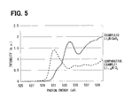
- FIG. 5 is a graph showing a measurement result of the X-ray absorption fine structure (XAFS) analytical method on a positive electrode material of Example 10.
- XAFS X-ray absorption fine structure
- the present inventors focused on a structure of a positive electrode material, and found that the above problem was solved by the following: the M 2 element and oxygen have a chemical bond in a positive electrode material containing a large amount of the M 2 element, which is bonded strongly to oxygen, in addition to the Ni element.
- the positive electrode material of the present disclosure contains Ni in its composition. This Ni forms a local structure with 6-coordinated oxygen (0). As a result, stable charge/discharge is performed. Further, a large amount of Ni as a redox species is contained in the range of 0.50 ⁇ 1.33, thus leading to achievement of high capacity.
- the M 1 element and the M 2 element are contained, thereby to further stabilize the crystal structure and reduce destruction of the bonding structure during charge/discharge. As a result, a decrease in battery capacity is reduced.
- the M 2 element strongly fixes oxygen. This results in reduction in desorption of oxygen which is concerned at the time of thermal-runaway, thus leading to further improvement in safety of the battery.
- the amount of the M 2 element is 0.33 or larger, on average, all of the oxygen in the Ni layer is adjacent to the M 2 element and bonded to the M 2 element, thus significantly enhancing the effect to reduce the oxygen desorption.
- the positive electrode material of the present disclosure can be excellent in conductivity of Li ions.
- the Li layer is a layer formed with Li as a main component, and is a layer substantially composed of Li.
- the Ni layer is a layer formed with Ni (Ni compound) as a main component, and is substantially a layer containing Ni, the M 1 element, and the M 2 element as main components.
- the main component means a component having the largest content ratio.
- the positive electrode material of the present disclosure has an M 2 -O chemical bond.
- the bonding state between the M 2 element and oxygen can be seen by use of a conventionally known analysis method (device). It is particularly preferably to distinguish a local structure of oxygen by analysis of an X-ray absorption fine structure (hereinafter referred to as XAFS).
- XAFS X-ray absorption fine structure
- XANES X-ray absorption near-edge structure
- EXAFS extended X-ray absorption fine structure
- XAFS X-ray absorption fine structure
- the spectrum structure of XANES reflects a density of a measured element in an empty state, to cope with a shift of atoms constituting the measured material from the core level to a variety of empty levels.
- the positive electrode material of the present disclosure preferably has an absorption edge peak in the range of 532 eV to 535 eV in the XANES spectrum at an oxygen K absorption edge measured by an X-ray absorption fine structure (XAFS) analytical method. By having a peak in this range, the positive electrode material can be confirmed to have the M 2 -O chemical bond.
- XAFS X-ray absorption fine structure
- the positive electrode for a non-aqueous electrolyte secondary battery and the non-aqueous electrolyte secondary battery according to the present disclosure are formed by using the positive electrode material of the present disclosure, and can exert an effect obtained by the positive electrode material of the present disclosure.
- a coin type lithium-ion secondary battery 1 a configuration of which is shown by a schematic sectional view in FIG. 1 is used.
- the lithium-ion secondary battery 1 of the present embodiment is a secondary battery (non-aqueous electrolyte secondary battery) formed by using a positive electrode (positive electrode for a non-aqueous electrolyte secondary battery) including the positive electrode material of the present disclosure as a positive electrode active material.
- the lithium-ion secondary battery 1 of the present embodiment includes a positive electrode case 11 , a sealing member 12 (gasket), a non-aqueous electrolyte 13 , a positive electrode 14 , a positive electrode current collector 140 , a positive electrode mixture layer 141 , a separator 15 , a negative electrode case 16 , a negative electrode 17 , a negative electrode current collector 170 , a negative electrode mixture layer 171 , a holding member 18 , and the like.
- the positive electrode 14 of the lithium-ion secondary battery 1 of the present embodiment includes the positive electrode mixture layer 141 containing the positive electrode active material formed of the positive electrode material of the present embodiment.
- the positive electrode mixture layer 141 includes, as necessary, a member such as a binder or a conductive material, other than the positive electrode active material.
- the positive electrode material is represented by Li 2 Ni ⁇ M 1 ⁇ M 2 ⁇ Mn ⁇ O 4- ⁇ (0.50 ⁇ 1.33, 0.33 ⁇ 1.1, 0 ⁇ 1.00, 0 ⁇ 0.67, 0 ⁇ 1.00, M 1 : at least one selected from Co, Ga, M 2 : at least one selected from Ge, Sn, Sb).
- the positive electrode material of the present embodiment contains Ni (transition metal) in its composition. This Ni forms a local structure with 6-coordinated oxygen (O) (6-coordinated local structure). As a result, stable charge/discharge is performed. A large amount of Ni as a redox species is contained in the range of 0.50 ⁇ 1.33, thus leading to achievement of high capacity.
- the M 1 element and the M 2 element are contained, thereby to further stabilize the crystal structure and reduce destruction of the bonding structure during charge/discharge, and as a result, a decrease in battery capacity is reduced.
- the M 2 element strongly fixes oxygen. This results in reduction in desorption of oxygen which is concerned at the time of thermal-runaway, thus leading to further improvement in safety of the battery.
- the amount of the M 2 element is 0.33 or larger, on average, all of the oxygen in the Ni layer is adjacent to the M 2 element and bonded to the M 2 element, thus significantly enhancing the effect to reduce the oxygen desorption.
- a non-aqueous electrolyte secondary battery (lithium ion battery) is overcharged, a malfunction may occur. Occurrence of the malfunction in this battery is greatly influenced by oxygen which is released from the positive electrode active material (positive electrode material) in the process to the occurrence. Specifically, electrons are taken from oxygen of the positive electrode active material during charge, thus making oxygen apt to be released.
- the M 2 element is added in the positive electrode material of the present disclosure, and the added M 2 element is bonded more strongly to oxygen than Ni or Mn (transition metal). That is, addition of the M 2 element can reduce oxygen desorption during charge/discharge to the minimum.
- the positive electrode material of the present embodiment has a layered structure including the Li layer and the Ni layer. With this configuration, the positive electrode has excellent conductivity of Li ions. It is to be noted that the Li layer is a layer formed with Li as a main component, and is a layer substantially composed of Li.
- the Ni layer is a layer formed with Ni (Ni compound) as a main component, and is substantially a layer containing Ni, the M 1 element, and M 2 element as main components.
- the positive electrode material of the present embodiment has an M 2 -O chemical bond.
- O is strongly fixed to the M 2 element in the positive electrode material. This results in reduction in desorption of oxygen which is concerned at the time of thermal-runaway, thus leading to further improvement in safety of the battery. Consequently, the safety is excellent with the positive electrode material of the present embodiment.
- the measuring method is not limited because of the M 2 -O chemical bond.
- the bond can be confirmed by the XAFS analytical method.
- the positive electrode material of the present embodiment preferably has an absorption edge peak in the range of 532 eV to 535 eV in the XANES spectrum at an oxygen K absorption edge measured by the XAFS analytical method.
- the positive electrode material can be confirmed to have the M 2 -O chemical bond.
- the M 1 element and the M 2 element are preferably in a 6-coordinated state, and with this configuration, a structural gap with the adjacent transition metal element (a coordination structure of Ni) can be made small and the durability can further be improved.
- the positive electrode material of the present embodiment may further contain Mn which is a transition metal in its composition (at the ratio of not smaller than 0 and not larger than 1.00). Similarly to Ni, this Mn forms a local structure with 6-coordinated oxygen (O) (6-coordinated local structure). By being contained at this ratio, Mn exerts the effect of stabilizing the Ni layer.
- the positive electrode active material has to include the above positive electrode material as the positive electrode active material, and may further include another positive electrode active material (positive electrode material).
- the other positive electrode active material may either be another material included in the above chemical expression, or be still another component.
- the lithium-ion secondary battery 1 of the present embodiment can be configured similarly to the conventional lithium-ion secondary battery except for the use of the above positive electrode material as the positive electrode active material.
- the positive electrode mixture layer 141 is formed by applying, to the positive electrode current collector 140 , a positive electrode mixture obtained by mixing the positive electrode active material, a conductive material, and a binder.
- the conductive material ensures electrical conductivity of the positive electrode 14 .
- Examples of the conductive material to be used may include, but are not limited to, fine particles of graphite, acetylene black, Ketjen black, carbon black such as carbon nanofiber, fine particles of amorphous carbon such as needle coke.
- the binder binds positive electrode active material particles or the conductive material.
- the binder to be used may include, but are not limited to, PVDF, EPDM, SBR, NBR, fluoro-rubber, and the like.
- the positive electrode mixture is dispersed in a solvent and applied to the positive electrode current collector 140 .
- the solvent normally, an organic solvent for dissolving the binder is used.
- the solvent may include, but are not limited to, NMP, dimethylformamide, dimethylacetamide, methyl ethyl ketone, cyclohexanone, methyl acetate, methyl acrylate, diethyltriamine, N,N-dimethylaminopropylamine, ethylene oxide, and tetrahydrofuran.
- a dispersant, a thickener or the like may be added to water to form the positive electrode active material into a slurry by PTFE or the like.
- Examples of the positive electrode current collector 140 to be used may include, but are not limited to, products obtained by processing a metal such as aluminum or stainless, specifically a foil processed into a sheet, net, punched metal, or a formed metal.
- the non-aqueous electrolyte 13 obtained by dissolving a supporting electrolyte into an organic solvent is used.
- the kind of the supporting electrolyte of the non-aqueous electrolyte 13 is not particularly limited to, but is preferably one of mineral salts selected from LiPF 6 , LiBF 4 , LiClO 4 , and LiAsF 6 , derivatives of these mineral salts, organic salts selected from LiSO 3 CF 3 , LiC(SO 3 CF 3 ) 3 , LiN(SO 2 CF 3 ) 2 , LiN(SO 2 C 2 F 5 ) 2 , LiN(SO 2 CF 3 )(SO 2 C 4 F 9 ), and derivatives of these organic salts.
- These supporting electrolytes can make the battery performance more excellent, and can keep the battery performance higher also in a temperature range other than a room temperature.
- a concentration of the supporting electrolyte is not particularly limited, and it is preferable to appropriately select the concentration in consideration of the kinds of the supporting electrolyte and the organic solvent, according to the use.
- the organic solvent (non-aqueous solvent) into which the supporting electrolyte is dissolved is not particularly limited so long as the organic solvent is used for a normal non-aqueous electrolyte.
- carbonates, halogenated hydrocarbon, ethers, ketones, nitriles, lactones, oxolane compound, or the like can be used.
- propylene carbonate, ethylene carbonate, 1,2-dimethoxyethane, dimethyl carbonate, diethyl carbonate, ethyl methyl carbonate, vinylene carbonate, and the like, and mixed solvents of these are suitably used.
- the solubility, dielectric constant, and viscosity of the supporting electrolyte are made excellent and the charge/discharge efficiency of the battery is made high, which is preferred.
- the most preferable non-aqueous electrolyte 13 is obtained by dissolving the supporting electrolyte into the organic solvent.
- the negative electrode mixture layer 171 is formed by applying a negative electrode mixture, obtained by mixing a negative electrode active material and a binder, on the surface of the negative electrode current collector 170 .
- the negative electrode active material a conventional negative electrode active material can be used.
- a negative electrode active material containing at least one element of Sn, Si, Sb, Ge, and C can be cited.
- C is preferably a carbon material capable of storing and desorbing electrolytic ions of the lithium-ion secondary battery 1 (a carbon material having a Li storage capacity), and C is more preferably amorphous-coated natural graphite.
- negative electrode active materials particularly, Sn, Sb, and Ge are alloy materials with great changes in volume.
- These negative electrode active materials may form alloys with other metals, such as Ti—Si, Ag—Sn, Sn—Sb, Ag—Ge, Cu—Sn, and Ni—Sn.
- a carbon material As the conductive material, a carbon material, a metal powder, a conductive polymer, or the like can be used. From the viewpoint of the conductivity and the stability, it is preferable to use a carbon material such as acetylene black, Ketjen black, or carbon black.
- binder examples include polytetrafluoroethylene (PTFE), polyvinylidene fluoride (PVDF), a fluororesin copolymer (tetrafluoroethylene-hexafluoropropylene copolymer) SBR, acrylic rubber, fluoro-rubber, polyvinyl alcohol (PVA), styrene-maleic acid resin, sodium polyacrylate, and carboxylmethyl cellulose (CMC).
- PTFE polytetrafluoroethylene
- PVDF polyvinylidene fluoride
- SBR fluororesin copolymer
- acrylic rubber fluoro-rubber
- PVA polyvinyl alcohol
- styrene-maleic acid resin sodium polyacrylate
- CMC carboxylmethyl cellulose
- the solvent may include an organic solvent such as N-methyl-2-pyrrolidone (NMP), and water.
- NMP N-methyl-2-pyrrolidone
- the negative electrode current collector 170 it is possible to use a conventional current collector, and is possible to use a product obtained by processing a metal such as copper, stainless, titanium, and nickel, specifically foil processed into a sheet, a net, a punched metal or a formed metal, but these are not restrictive.
- the positive electrode case 11 and the negative electrode case 16 seal built-in contents by using the sealing member 12 .
- the built-in contents include the non-aqueous electrolyte 13 , the positive electrode 14 , the separator 15 , the negative electrode 17 , the holding member 18 , and the like.
- the positive electrode mixture layer 141 comes into surface contact with the positive electrode case 11 via the positive electrode current collector 140 , to make electrical conduction.
- the negative electrode mixture layer 171 comes into surface contact with the negative electrode case 16 via the negative electrode current collector 170 .
- the separator 15 interposed between the positive electrode mixture layer 141 and the negative electrode mixture layer 171 electrically insulates the positive electrode mixture layer 141 and the negative electrode mixture layer 171 , and holds the non-aqueous electrolyte 13 .
- a porous synthetic resin film especially a porous film of a polyolefin polymer (polyethylene, polypropylene) is used.
- the separator 15 is molded into a larger size than sizes of the two mixture layers 141 , 171 so as to ensure electrical insulation between the two mixture layers 141 , 171 .
- the holding member 18 serves to hold the positive electrode current collector 140 , the positive electrode mixture layer 141 , the separator 15 , the negative electrode mixture layer 171 , and the negative electrode current collector 170 at regular positions.
- the use of an elastic member such as an elastic piece or a spring facilitates holding of those at the regular positions.
- the lithium-ion secondary battery 1 of the present embodiment has the coin shape as described above, but the shape is not particularly limited.
- the lithium-ion secondary battery can be a battery in a variety of shapes such as a cylindrical shape and a prismatic shape, or an irregularly shaped battery sealed in a laminated exterior body.
- a manufacturing method for the positive electrode material of the present embodiment is not limited so long as the positive electrode material has the above configuration.
- Examples of the manufacturing method may include a solid-phase synthesis method, a co-precipitation synthesis method, a polymerized complex synthesis method, a method through ion exchange, a synthesis method by high temperature and high pressure treatment, a sol-gel method, a spray dry method, and a supercritical method.
- the examples of the manufacturing method may include a method of using these methods singly or in combination.
- a positive electrode material positive electrode active material
- a positive electrode and a lithium-ion secondary battery using the positive electrode material were manufactured.
- the lithium-ion secondary battery shown in FIG. 1 was manufactured.
- Na 2 NiSnO4 as a starting material was manufactured. Specifically, a compound containing one or more elements of Na, Ni, and Sn was weighed and mixed such that these elements were at a predetermined atomic ratio. Then, the compound was sintered (in an atmosphere), to obtain a starting material having an almost single-phase crystal structure.
- Li 2 NiSnO 4 was heated in a molten salt composed of lithium nitrate and lithium chloride, to carry out ion-exchange treatment.
- Li 2 NiSnO 4 powder Li 2 NiSnO 4 powder
- Aqueous solutions containing respective metal complexes of Li, Ni, Mn and Ge were prepared.
- the obtained complex solutions were mixed such that a composition ratio thereof was a composition ratio of a target positive electrode material, namely, an atomic ratio of Li:Ni:Mn:Ge was 2:1:0.67:0.33.
- the obtained mixed solution was dried in a drying oven to remove an organic component by heating treatment, which was then calcined and sintered.
- Li 2.1 NiMn 0.67 Ge 0.33 O 4 powder Li 2.1 NiMn 0.67 Ge 0.33 O 4 powder
- powder XRD powder XRD
- a positive electrode material Li 2 NiMn 0.67 Ge 0.33 O 4 powder of the present example was manufactured.
- the manufactured positive electrode material was observed by powder XRD, it was confirmed that the powder was an almost single-phase compound.
- a positive electrode material (Li 2.1 NiMn 0.67 Sn 0.33 O 4 powder) of the present example was manufactured from an aqueous solution containing respective metal complexes.
- the manufactured positive electrode material was observed by powder XRD, it was confirmed that the powder was an almost single-phase compound.
- the positive electrode material (Li 2 NiMn 0.67 Sn 0.33 O 4 powder) of the present example was manufactured.
- the manufactured positive electrode material was observed by powder XRD, it was confirmed that the powder was an almost single-phase compound.
- a positive electrode material (L i2.1 Ni 0.67 Co 0.33 Mn 0.33 Ge 0.33 O 4 ) of the present example was manufactured from an aqueous solution containing respective metal complexes.
- a positive electrode material (Li 2.1 Ni 0.88 Co 0.22 Mn 0.44 Ge 0.44 O 4 powder) of the present example was manufactured from an aqueous solution containing respective metal complexes.
- the positive electrode material of the present example was a compound having a composition Li 2 NiGeO 4 and a layered rock-salt crystal structure, and indexible in a space group R3m (or C2/m). Further, it was also confirmed by power XRD that the positive electrode material of the present example was an almost single-phase material.
- a positive electrode material (Li 1.05 NiO 2 powder) of the present example was manufactured from an aqueous solution containing respective metal complexes.
- the manufactured Li 1.05 NiO 2 powder was observed by powder XRD, it was confirmed that the powder was an almost single-phase compound.
- an absorption edge peak was in the range of 532 eV to 535 eV.
- a peak can be confirmed in the range of 532 eV to 533 eV. This peak is caused by a Sn—O bond. That is, the positive electrode material of Example 1 has the Sn—O bond.
- a peak can be confirmed in the vicinity of 530 eV. That is, the material does not have a peak in the range of 532 eV to 535 eV. This peak is caused by a Ni—O bond.
- the positive electrode material of Example 2 has the Ge—O bond.
- the positive electrode material of Example 2 has the Sn—O bond.
- a lithium-ion secondary battery was assembled, to evaluate charge/discharge characteristics. Further, after measurement of the charge/discharge characteristics, the coin type battery was disassembled and the positive electrode was taken out, to evaluate the safety.
- test cell (2032 coin type half cell) made of the lithium-ion secondary battery was assembled, to perform evaluation.
- a test cell (coin type half cell) has a similar configuration to that of the coin type lithium-ion secondary battery 1 , the configuration of which was shown in FIG. 1 .
- the positive electrode there was used a positive electrode with the positive electrode mixture layer 141 formed by applying a positive electrode mixture, obtained by mixing 91 parts by mass of the positive electrode active material (positive electrode active material of each example), 2 parts by mass of acetylene black, and 7 parts by mass of PVDF, to the positive electrode current collector 140 made of aluminum foil.
- a positive electrode mixture obtained by mixing 91 parts by mass of the positive electrode active material (positive electrode active material of each example), 2 parts by mass of acetylene black, and 7 parts by mass of PVDF, to the positive electrode current collector 140 made of aluminum foil.
- the non-aqueous electrolyte 13 was prepared by dissolving LiPF 6 into a mixed solvent of 30 vol % of ethylene carbonate (EC) and 70 vol % of diethyl carbonate (DEC) such that 1 mol/l of LiPF 6 was contained.
- EC ethylene carbonate
- DEC diethyl carbonate
- test cell After being assembled, the test cell was subjected to activation treatment by 1 ⁇ 3 C ⁇ 2 cycles of charge/discharge.
- test cell (half cell) of each example was manufactured.
- the lithium-ion secondary battery was charged and discharged at the rate of 1/50 C.
- the charge was performed by CC charge with 4.5-V cut off, and the discharge was performed by CC discharge with 2.6-V cut off.
- Table 1 shows measurement results of a charging capacity and a discharging capacity of the lithium-ion secondary batteries of example (Examples 1 to 10, Comparative Example 1).
- the secondary batteries of the examples have the excellent charging capacity and the discharging capacity compared to that of Comparative Example 1.
- the lithium-ion secondary battery was charged by CC charge at the rate of 1/50 C up to 4.8 V.
- the battery was disassembled and the positive electrode was taken out.
- the taken-out positive electrode was washed by DMC, and then heated in a helium atmosphere from a room temperature to 1000° C. with a programming rate of 20° C./min. An amount of oxygen generated from the positive electrode at that time was measured by TPD-MS measurement.
- the use of the positive electrode material (positive electrode) of each example makes the secondary battery generate a small amount of oxygen and have excellent safety.
Landscapes
- Chemical & Material Sciences (AREA)
- Chemical Kinetics & Catalysis (AREA)
- Electrochemistry (AREA)
- General Chemical & Material Sciences (AREA)
- Inorganic Chemistry (AREA)
- Composite Materials (AREA)
- Engineering & Computer Science (AREA)
- Manufacturing & Machinery (AREA)
- Battery Electrode And Active Subsutance (AREA)
- Inorganic Compounds Of Heavy Metals (AREA)
Abstract
A positive electrode material includes: Li2NiαM1 βM2 γMnηO4-ε; a layered structure including a Li layer and a Ni layer; and a chemical bond of M2-O. α satisfies an equation of 0.50<α≤1.33. β satisfies an equation of 0≤β<0.67. γ satisfies an equation of 0.33≤γ≤1.1. η satisfies an equation of 0≤η≤1.00. ε satisfies an equation of 0≤ε≤1.00. M1 represents at least one selected from Co and Ga. M2 represents at least one selected from Ge, Sn and Sb.
Description
This application is based on Japanese Patent Application No. 2015-71718 filed on Mar. 31, 2015, the disclosure of which is incorporated herein by reference.
The present disclosure relates to a positive electrode material, a positive electrode for a non-aqueous electrolyte secondary battery, and a non-aqueous electrolyte secondary battery formed by using the positive electrode.
With the spread of electronic devices such as notebook computers, mobile phones, and digital cameras, the demand for secondary batteries for driving these electronic devices is on the increase. In recent years, these electronic devices have increasingly high power consumption with enhancement of functionalities thereof and have been expected to be reduced in size, and hence improvement in performance of the secondary batteries has been required. Among the secondary batteries, a non-aqueous electrolyte secondary battery (particularly, a lithium-ion secondary battery) can be increased in capacity, and this battery has thus been applied to a variety of electronic devices.
Generally, a non-aqueous electrolyte secondary battery has a configuration in which a positive electrode and a negative electrode are connected via a non-aqueous electrolyte (non-aqueous electrolytic solution), and stored in a battery case. In the positive electrode, a positive electrode active material layer containing a positive electrode material typified by a positive electrode active material is formed on the surface of a positive electrode current collector. In the negative electrode, a negative electrode active material layer containing a negative electrode active material is formed on the surface of a negative electrode current collector.
In a lithium-ion secondary battery as a typical example of the non-aqueous electrolyte secondary battery, a lithium composite oxide is used as a positive electrode material (positive electrode active material). This composite oxide is described in Patent Literatures 1 to 8, for example.
Patent Literature 3 describes a positive electrode active material obtained by mixing LixMnMO4 and LiNiMO2 (both of M are selected from predetermined elements). This positive electrode active material is excellent in battery performance after storage at high temperature.
Patent Literature 4 describes a positive electrode active material in which a portion of Li lacks in LiMnMO2 having a layered polycrystalline structure (both of M are selected from predetermined elements). In this positive electrode, distortion and a chemical bond in the crystal are stabilized, to obtain effects of cycle stability during charge/discharge, durable stability, and the like.
Patent Literature 5 describes a positive electrode active material obtained by replacing a portion of Li and a portion of Co with a predetermined M element in LiCoO2 (both of M are selected from predetermined elements). In this positive electrode active material, by replacement of Li and Co with the M element, binding force between a lithium layer and a cobalt layer is strengthened and distortion between the layers and expansion of a crystal lattice are reduced, to obtain the effects of cycle stability during charge/discharge, durable stability, and the like.
Patent Literature 6 describes a positive electrode active material obtained by mixing LiNiMnCoO2 and Li2MO3 (M is selected from predetermined elements). This positive electrode active material layer includes an active material which exerts an excellent effect on battery capacity and safety and an active material which exerts an effect on cycle characteristics and storage characteristics.
However, any of these positive electrode active materials (positive electrode materials) cannot sufficiently reduce destruction of the crystal structure during charge/discharge, leading to a decrease in capacity of the non-aqueous electrolyte secondary battery, which has been problematic.
For the safety, Non Patent Literature 1 describes a technique of forming a positive electrode containing Ti, namely LiNiMnTiO2.
However, it is described that addition of Ti as described in this Non Patent Literature 1 does not significantly improve the safety.
As another attempt to achieve both the safety and high stability of crystals, Non Patent Literature 2 describes a technique of forming a positive electrode active material that contains Si, having strong binding force with oxygen, in the same amount as that of a transition metal, Namely Li2MnSiO4.
However, the transition metal takes a 4-coordinated coordination structure in this positive electrode active material, causing instability of the structure during charge, and after all, it is not a positive electrode active material having sufficient durability.
Patent Literature 7 describes a positive electrode active material having Li oxide represented by a Li[LixMeyM′z]O2+d(x+y+z=1, 0<x<0.33, 0.05≤y≤0.15, 0<d≤0.1, Me: at least one selected from Mn, V, Cr, Fe, Co, Ni, Al and B, and M′: at least one selected from Ge, Ru, Sn, Ti, Nb and Pt).
However, in a battery using this positive electrode active material, improvement in safety has not been sufficient. Specifically, an addition ratio of the element Me in the transition metal is approximately 14 at %, and there exist oxygen atoms not bonded to the element Me. The chemical bond between the oxygen atoms and the element Me is strong, and chemical bond cleavage (oxygen desorption) hardly occurs. That is, the oxygen atoms not bonded to the element Me contained in the positive electrode active material of Patent Literature 7 become oxygen gas when the battery is formed, which causes deterioration in safety of the battery.
Patent Literature 8 describes that, by having a positive electrode active material with an x-ray absorption spectrum at an oxygen K absorption edge measured by an X-ray absorption fine structure (XAFS) analytical method in which an absorption edge peak that appears in the vicinity of an oxygen K absorption edge at 530 eV shows a certain behavior, reaction on the interface in a charged state is reduced, to improve the battery performance.
However, while the positive electrode active material described in Patent Literature 8 brings an effect of stabilizing the crystal structure on the surface of the positive electrode active material, it has not brought a sufficient effect in terms of safety. Specifically, in the lithium-ion secondary battery (non-aqueous electrolyte secondary battery), there has been a possibility that a crystal structure of a lithium composite oxide used for the positive electrode active material is destructed due to overcharge or the like, to release contained oxygen.
Patent Literature 1: JP 2007-188703-A
Patent Literature 2: JP 2008-127233-A (corresponding to US 2008/116418 A1)
Patent Literature 3: JP 2001-345101-A (corresponding to US 2005/0191551 A1 and US 2002/0012842 A1)
Patent Literature 4: JP 2001-250551-A (corresponding to US 2001/0024753 A1)
Patent Literature 5: Japanese Patent No. 3782058 B (corresponding to US 2003/0013017 A1)
Patent Literature 6: JP 2006-202702
Patent Literature 7: U.S. Pat. No. 8,734,994
Patent Literature 8: JP 2008-127234-A
Non Patent Literature 1: Seung-Taek Myung, and five others, “Synthesis of LiNi0.5Mn0.5−xTixO2 by an Emulsion Drying Method and Effect of Ti on Structure and Electrochemical Properties”, Chemistry of Materials, 2005, vol. 17, p. 2427-2435
Non Patent Literature 2: R. Dominko Li2MSiO4 (M=Fe and/or Mn) cathode materials, Journal of Power Sources, 2008, vol. 184, p. 462-468
It is an object of the present disclosure to provide a positive electrode material, a positive electrode for a non-aqueous electrolyte secondary battery, and a non-aqueous electrolyte secondary battery, which reduce destruction of a crystal structure during charge/discharge and are excellent in safety.
According to a first aspect of the present disclosure, a positive electrode material includes: Li2NiαM1 βM2 γMnηO4-ε; a layered structure including a Li layer and a Ni layer; and a chemical bond of M2-O. α satisfies an equation of 0.50<α≤1.33. β satisfies an equation of 0≤β<0.67. γ satisfies an equation of 0.33≤γ≤1.1. η satisfies an equation of 0≤η≤1.00. ε satisfies an equation of 0≤ε≤1.00. M1 represents at least one selected from Co and Ga. M2 represents at least one selected from Ge, Sn and Sb.
The above positive electrode material includes Ni in its composition. This Ni forms a local structure with 6-coordinated oxygen (O). As a result, stable charge/discharge is performed. Further, a large amount of Ni as a redox species is contained in the range of 0.50<α≤1.33, thus leading to achievement of high capacity.
Moreover, large amounts of the M1 element and the M2 element are included, thereby to further stabilize the crystal structure and reduce destruction of the bonding structure during charge/discharge. As a result, a decrease in battery capacity is reduced. The M2 element strongly fixes oxygen. This results in reduction in desorption of oxygen which is concerned at the time of thermal-runaway, thus leading to further improvement in safety of the battery. Moreover, when the amount of the M2 element is 0.33 or larger, on average, all of the oxygen in the Ni layer is adjacent to the M2 element and bonded to the M2 element, thus significantly enhancing the effect to reduce oxygen desorption.
By having a layered structure that includes the Li layer and the Ni layer, the positive electrode material of the present invention can be excellent in conductivity of Li ions. It is to be noted that the Li layer is a layer formed with Li as a main component, and is a layer substantially composed of Li. The Ni layer is a layer formed with Ni (Ni compound) as a main component, and is substantially a layer containing Ni, the M1 element, and the M2 element as main components. In addition, the main component means a component having the largest content ratio.
The above positive electrode material has an M2-O chemical bond. By the positive electrode material having the M2-O chemical bond, desorption of oxygen which is concerned at the time of thermal-runaway is reduced, thus leading to further improvement in safety of the battery.
According to a second aspect of the present disclosure, a positive electrode for a non-aqueous electrolyte secondary battery includes: the positive electrode material according to the first aspect of the present disclosure.
The above positive electrode for a non-aqueous electrolyte secondary battery is formed by using the positive electrode material of the first aspect of the present disclosure, and exerts an effect obtained by the positive electrode material.
According to a third aspect of the present disclosure, a non-aqueous electrolyte secondary battery includes: a positive electrode for a non-aqueous electrolyte secondary battery including the positive electrode material according to the first aspect of the present disclosure.
The above non-aqueous electrolyte secondary battery is formed by using the positive electrode material of the first aspect of the present disclosure, and exerts an effect obtained by the positive electrode material.
The above and other objects, features and advantages of the present disclosure will become more apparent from the following detailed description made with reference to the accompanying drawings. In the drawings:
In order to solve the above problem, the present inventors focused on a structure of a positive electrode material, and found that the above problem was solved by the following: the M2 element and oxygen have a chemical bond in a positive electrode material containing a large amount of the M2 element, which is bonded strongly to oxygen, in addition to the Ni element.
The positive electrode material of the present disclosure contains Ni in its composition. This Ni forms a local structure with 6-coordinated oxygen (0). As a result, stable charge/discharge is performed. Further, a large amount of Ni as a redox species is contained in the range of 0.50<α≤1.33, thus leading to achievement of high capacity.
Moreover, large amounts of the M1 element and the M2 element are contained, thereby to further stabilize the crystal structure and reduce destruction of the bonding structure during charge/discharge. As a result, a decrease in battery capacity is reduced. The M2 element strongly fixes oxygen. This results in reduction in desorption of oxygen which is concerned at the time of thermal-runaway, thus leading to further improvement in safety of the battery. Moreover, when the amount of the M2 element is 0.33 or larger, on average, all of the oxygen in the Ni layer is adjacent to the M2 element and bonded to the M2 element, thus significantly enhancing the effect to reduce the oxygen desorption.
By having a layered structure that includes the Li layer and the Ni layer, the positive electrode material of the present disclosure can be excellent in conductivity of Li ions. It is to be noted that the Li layer is a layer formed with Li as a main component, and is a layer substantially composed of Li. The Ni layer is a layer formed with Ni (Ni compound) as a main component, and is substantially a layer containing Ni, the M1 element, and the M2 element as main components. In addition, the main component means a component having the largest content ratio.
The positive electrode material of the present disclosure has an M2-O chemical bond. By the positive electrode material having the M2-O chemical bond, desorption of oxygen which is concerned at the time of thermal-runaway is reduced, thus leading to further improvement in safety of the battery.
The bonding state between the M2 element and oxygen can be seen by use of a conventionally known analysis method (device). It is particularly preferably to distinguish a local structure of oxygen by analysis of an X-ray absorption fine structure (hereinafter referred to as XAFS). Hereinafter, a general XAFS will be briefly described.
When absorbance of a substance is measured with incident X-ray energy being changed, an abrupt increase in absorbance (absorption edge) is observed when the incident X-ray energy is equal to a core level of atoms constituting the measured material. Thereafter, with an increase in incident X-ray energy, gentle attenuation of the absorbance is observed. When this spectrum is examined in detail, there is found a spectrum structure with a large change in the vicinity of the absorption edge. Further, also in a higher energy region than the absorption edge, there is a spectrum structure having a gentle, though small, vibration structure.
The former is called an X-ray absorption near-edge structure (XANES), and the latter is called an extended X-ray absorption fine structure (EXAFS). Both are collectively called an X-ray absorption fine structure (XAFS).
The spectrum structure of XANES reflects a density of a measured element in an empty state, to cope with a shift of atoms constituting the measured material from the core level to a variety of empty levels.
The positive electrode material of the present disclosure preferably has an absorption edge peak in the range of 532 eV to 535 eV in the XANES spectrum at an oxygen K absorption edge measured by an X-ray absorption fine structure (XAFS) analytical method. By having a peak in this range, the positive electrode material can be confirmed to have the M2-O chemical bond.
The positive electrode for a non-aqueous electrolyte secondary battery and the non-aqueous electrolyte secondary battery according to the present disclosure are formed by using the positive electrode material of the present disclosure, and can exert an effect obtained by the positive electrode material of the present disclosure.
Hereinafter, the present disclosure will be described in detail with reference to embodiments.
In the present embodiment, a coin type lithium-ion secondary battery 1, a configuration of which is shown by a schematic sectional view in FIG. 1 is used. The lithium-ion secondary battery 1 of the present embodiment is a secondary battery (non-aqueous electrolyte secondary battery) formed by using a positive electrode (positive electrode for a non-aqueous electrolyte secondary battery) including the positive electrode material of the present disclosure as a positive electrode active material.
The lithium-ion secondary battery 1 of the present embodiment includes a positive electrode case 11, a sealing member 12 (gasket), a non-aqueous electrolyte 13, a positive electrode 14, a positive electrode current collector 140, a positive electrode mixture layer 141, a separator 15, a negative electrode case 16, a negative electrode 17, a negative electrode current collector 170, a negative electrode mixture layer 171, a holding member 18, and the like.
The positive electrode 14 of the lithium-ion secondary battery 1 of the present embodiment includes the positive electrode mixture layer 141 containing the positive electrode active material formed of the positive electrode material of the present embodiment. The positive electrode mixture layer 141 includes, as necessary, a member such as a binder or a conductive material, other than the positive electrode active material.
(Positive Electrode Material)
The positive electrode material is represented by Li2NiαM1 βM2 γMnηO4-ε (0.50<α≤1.33, 0.33≤γ≤1.1, 0≤η≤1.00, 0≤β<0.67, 0≤ε≤1.00, M1: at least one selected from Co, Ga, M2: at least one selected from Ge, Sn, Sb).
The positive electrode material of the present embodiment contains Ni (transition metal) in its composition. This Ni forms a local structure with 6-coordinated oxygen (O) (6-coordinated local structure). As a result, stable charge/discharge is performed. A large amount of Ni as a redox species is contained in the range of 0.50<α≤1.33, thus leading to achievement of high capacity.
Moreover, large amounts of the M1 element and the M2 element are contained, thereby to further stabilize the crystal structure and reduce destruction of the bonding structure during charge/discharge, and as a result, a decrease in battery capacity is reduced. The M2 element strongly fixes oxygen. This results in reduction in desorption of oxygen which is concerned at the time of thermal-runaway, thus leading to further improvement in safety of the battery. Moreover, when the amount of the M2 element is 0.33 or larger, on average, all of the oxygen in the Ni layer is adjacent to the M2 element and bonded to the M2 element, thus significantly enhancing the effect to reduce the oxygen desorption.
A non-aqueous electrolyte secondary battery (lithium ion battery) is overcharged, a malfunction may occur. Occurrence of the malfunction in this battery is greatly influenced by oxygen which is released from the positive electrode active material (positive electrode material) in the process to the occurrence. Specifically, electrons are taken from oxygen of the positive electrode active material during charge, thus making oxygen apt to be released. The M2 element is added in the positive electrode material of the present disclosure, and the added M2 element is bonded more strongly to oxygen than Ni or Mn (transition metal). That is, addition of the M2 element can reduce oxygen desorption during charge/discharge to the minimum.
The positive electrode material of the present embodiment has a layered structure including the Li layer and the Ni layer. With this configuration, the positive electrode has excellent conductivity of Li ions. It is to be noted that the Li layer is a layer formed with Li as a main component, and is a layer substantially composed of Li. The Ni layer is a layer formed with Ni (Ni compound) as a main component, and is substantially a layer containing Ni, the M1 element, and M2 element as main components.
The positive electrode material of the present embodiment has an M2-O chemical bond. By the positive electrode material having the M2-O chemical bond, O is strongly fixed to the M2 element in the positive electrode material. This results in reduction in desorption of oxygen which is concerned at the time of thermal-runaway, thus leading to further improvement in safety of the battery. Consequently, the safety is excellent with the positive electrode material of the present embodiment.
It is to be noted that the measuring method is not limited because of the M2-O chemical bond. For example, the bond can be confirmed by the XAFS analytical method.
The positive electrode material of the present embodiment preferably has an absorption edge peak in the range of 532 eV to 535 eV in the XANES spectrum at an oxygen K absorption edge measured by the XAFS analytical method.
By having a peak in this range, the positive electrode material can be confirmed to have the M2-O chemical bond.
In the positive electrode material of the present embodiment, the M1 element and the M2 element are preferably in a 6-coordinated state, and with this configuration, a structural gap with the adjacent transition metal element (a coordination structure of Ni) can be made small and the durability can further be improved.
The positive electrode material of the present embodiment may further contain Mn which is a transition metal in its composition (at the ratio of not smaller than 0 and not larger than 1.00). Similarly to Ni, this Mn forms a local structure with 6-coordinated oxygen (O) (6-coordinated local structure). By being contained at this ratio, Mn exerts the effect of stabilizing the Ni layer.
The positive electrode active material has to include the above positive electrode material as the positive electrode active material, and may further include another positive electrode active material (positive electrode material). The other positive electrode active material may either be another material included in the above chemical expression, or be still another component.
(Configuration Other Than Positive Electrode Active Material)
The lithium-ion secondary battery 1 of the present embodiment can be configured similarly to the conventional lithium-ion secondary battery except for the use of the above positive electrode material as the positive electrode active material.
In the positive electrode 14, the positive electrode mixture layer 141 is formed by applying, to the positive electrode current collector 140, a positive electrode mixture obtained by mixing the positive electrode active material, a conductive material, and a binder.
The conductive material ensures electrical conductivity of the positive electrode 14. Examples of the conductive material to be used may include, but are not limited to, fine particles of graphite, acetylene black, Ketjen black, carbon black such as carbon nanofiber, fine particles of amorphous carbon such as needle coke.
The binder binds positive electrode active material particles or the conductive material. Examples of the binder to be used may include, but are not limited to, PVDF, EPDM, SBR, NBR, fluoro-rubber, and the like.
The positive electrode mixture is dispersed in a solvent and applied to the positive electrode current collector 140. As the solvent, normally, an organic solvent for dissolving the binder is used. Examples of the solvent may include, but are not limited to, NMP, dimethylformamide, dimethylacetamide, methyl ethyl ketone, cyclohexanone, methyl acetate, methyl acrylate, diethyltriamine, N,N-dimethylaminopropylamine, ethylene oxide, and tetrahydrofuran. Further, a dispersant, a thickener or the like may be added to water to form the positive electrode active material into a slurry by PTFE or the like.
Examples of the positive electrode current collector 140 to be used may include, but are not limited to, products obtained by processing a metal such as aluminum or stainless, specifically a foil processed into a sheet, net, punched metal, or a formed metal.
(Non-Aqueous Electrolyte)
The non-aqueous electrolyte 13 obtained by dissolving a supporting electrolyte into an organic solvent is used.
The kind of the supporting electrolyte of the non-aqueous electrolyte 13 is not particularly limited to, but is preferably one of mineral salts selected from LiPF6, LiBF4, LiClO4, and LiAsF6, derivatives of these mineral salts, organic salts selected from LiSO3CF3, LiC(SO3CF3)3, LiN(SO2CF3)2, LiN(SO2C2F5)2, LiN(SO2CF3)(SO2C4F9), and derivatives of these organic salts. These supporting electrolytes can make the battery performance more excellent, and can keep the battery performance higher also in a temperature range other than a room temperature. A concentration of the supporting electrolyte is not particularly limited, and it is preferable to appropriately select the concentration in consideration of the kinds of the supporting electrolyte and the organic solvent, according to the use.
The organic solvent (non-aqueous solvent) into which the supporting electrolyte is dissolved is not particularly limited so long as the organic solvent is used for a normal non-aqueous electrolyte. For example, carbonates, halogenated hydrocarbon, ethers, ketones, nitriles, lactones, oxolane compound, or the like can be used. In particular, propylene carbonate, ethylene carbonate, 1,2-dimethoxyethane, dimethyl carbonate, diethyl carbonate, ethyl methyl carbonate, vinylene carbonate, and the like, and mixed solvents of these are suitably used. By particularly using one or more non-aqueous electrolytes selected from the group consisting of carbonates and ethers out of the above cited organic solvents, the solubility, dielectric constant, and viscosity of the supporting electrolyte are made excellent and the charge/discharge efficiency of the battery is made high, which is preferred.
In the lithium-ion secondary battery 1 of the present embodiment, the most preferable non-aqueous electrolyte 13 is obtained by dissolving the supporting electrolyte into the organic solvent.
(Negative Electrode)
As for the negative electrode 17, the negative electrode mixture layer 171 is formed by applying a negative electrode mixture, obtained by mixing a negative electrode active material and a binder, on the surface of the negative electrode current collector 170.
As the negative electrode active material, a conventional negative electrode active material can be used. A negative electrode active material containing at least one element of Sn, Si, Sb, Ge, and C can be cited. Out of these negative electrode active materials, C is preferably a carbon material capable of storing and desorbing electrolytic ions of the lithium-ion secondary battery 1 (a carbon material having a Li storage capacity), and C is more preferably amorphous-coated natural graphite.
Further, out of these negative electrode active materials, particularly, Sn, Sb, and Ge are alloy materials with great changes in volume. These negative electrode active materials may form alloys with other metals, such as Ti—Si, Ag—Sn, Sn—Sb, Ag—Ge, Cu—Sn, and Ni—Sn.
As the conductive material, a carbon material, a metal powder, a conductive polymer, or the like can be used. From the viewpoint of the conductivity and the stability, it is preferable to use a carbon material such as acetylene black, Ketjen black, or carbon black.
Examples of the binder may include polytetrafluoroethylene (PTFE), polyvinylidene fluoride (PVDF), a fluororesin copolymer (tetrafluoroethylene-hexafluoropropylene copolymer) SBR, acrylic rubber, fluoro-rubber, polyvinyl alcohol (PVA), styrene-maleic acid resin, sodium polyacrylate, and carboxylmethyl cellulose (CMC).
Examples of the solvent may include an organic solvent such as N-methyl-2-pyrrolidone (NMP), and water.
As the negative electrode current collector 170, it is possible to use a conventional current collector, and is possible to use a product obtained by processing a metal such as copper, stainless, titanium, and nickel, specifically foil processed into a sheet, a net, a punched metal or a formed metal, but these are not restrictive.
(Other Configurations)
The positive electrode case 11 and the negative electrode case 16 seal built-in contents by using the sealing member 12. The built-in contents include the non-aqueous electrolyte 13, the positive electrode 14, the separator 15, the negative electrode 17, the holding member 18, and the like.
The positive electrode mixture layer 141 comes into surface contact with the positive electrode case 11 via the positive electrode current collector 140, to make electrical conduction. The negative electrode mixture layer 171 comes into surface contact with the negative electrode case 16 via the negative electrode current collector 170.
The separator 15 interposed between the positive electrode mixture layer 141 and the negative electrode mixture layer 171 electrically insulates the positive electrode mixture layer 141 and the negative electrode mixture layer 171, and holds the non-aqueous electrolyte 13. As the separator 15, for example, a porous synthetic resin film, especially a porous film of a polyolefin polymer (polyethylene, polypropylene) is used. The separator 15 is molded into a larger size than sizes of the two mixture layers 141, 171 so as to ensure electrical insulation between the two mixture layers 141, 171.
The holding member 18 serves to hold the positive electrode current collector 140, the positive electrode mixture layer 141, the separator 15, the negative electrode mixture layer 171, and the negative electrode current collector 170 at regular positions. The use of an elastic member such as an elastic piece or a spring facilitates holding of those at the regular positions.
The lithium-ion secondary battery 1 of the present embodiment has the coin shape as described above, but the shape is not particularly limited. The lithium-ion secondary battery can be a battery in a variety of shapes such as a cylindrical shape and a prismatic shape, or an irregularly shaped battery sealed in a laminated exterior body.
(Manufacturing Method)
A manufacturing method for the positive electrode material of the present embodiment is not limited so long as the positive electrode material has the above configuration. Examples of the manufacturing method may include a solid-phase synthesis method, a co-precipitation synthesis method, a polymerized complex synthesis method, a method through ion exchange, a synthesis method by high temperature and high pressure treatment, a sol-gel method, a spray dry method, and a supercritical method. Also, the examples of the manufacturing method may include a method of using these methods singly or in combination.
Hereinafter, the present disclosure will be described with reference to examples.
As examples for specifically describing the present disclosure, a positive electrode material (positive electrode active material), and a positive electrode and a lithium-ion secondary battery using the positive electrode material were manufactured. In the examples, the lithium-ion secondary battery shown in FIG. 1 was manufactured.
First, Na2NiSnO4 as a starting material was manufactured. Specifically, a compound containing one or more elements of Na, Ni, and Sn was weighed and mixed such that these elements were at a predetermined atomic ratio. Then, the compound was sintered (in an atmosphere), to obtain a starting material having an almost single-phase crystal structure.
Subsequently, the obtained Li2NiSnO4 was heated in a molten salt composed of lithium nitrate and lithium chloride, to carry out ion-exchange treatment.
In the above manner, a positive electrode material (Li2NiSnO4 powder) of the present example was manufactured. When the manufactured Li2NiSnO4 powder was observed by powder XRD, it was confirmed that the powder was an almost single-phase compound.
Aqueous solutions containing respective metal complexes of Li, Ni, Mn and Ge were prepared. The obtained complex solutions were mixed such that a composition ratio thereof was a composition ratio of a target positive electrode material, namely, an atomic ratio of Li:Ni:Mn:Ge was 2:1:0.67:0.33.
The obtained mixed solution was dried in a drying oven to remove an organic component by heating treatment, which was then calcined and sintered.
In the above manner, a positive electrode material (Li2.1NiMn0.67Ge0.33O4 powder) of the present example was manufactured. When the manufactured Li2.1NiMn0.67Ge0.33O4 powder was observed by powder XRD, it was confirmed that the powder was an almost single-phase compound.
Similarly to the starting material of Example 1, an almost single phase Na2NiMn0.67Ge0.33O4 was manufactured.
Subsequently, the obtained Na2NiMn0.67Ge0.33O4 was subjected to the ion-exchange treatment in a similar manner to the case of Example 1.
In the above manner, a positive electrode material (Li2NiMn0.67Ge0.33O4 powder) of the present example was manufactured. When the manufactured positive electrode material was observed by powder XRD, it was confirmed that the powder was an almost single-phase compound.
In a similar manner to the case of Example 2, a positive electrode material (Li2.1NiMn0.67Sn0.33O4 powder) of the present example was manufactured from an aqueous solution containing respective metal complexes. When the manufactured positive electrode material was observed by powder XRD, it was confirmed that the powder was an almost single-phase compound.
Similarly to the starting material of Example 1, an almost single phase Na2NiMn0.67Sn0.33O4 was manufactured.
Subsequently, the obtained Na2NiMn0.67Sn0.33O4 was subjected to the ion-exchange treatment in a similar manner to the case of Example 1.
In the above manner, the positive electrode material (Li2NiMn0.67Sn0.33O4 powder) of the present example was manufactured. When the manufactured positive electrode material was observed by powder XRD, it was confirmed that the powder was an almost single-phase compound.
In a similar manner to the case of Example 2, a positive electrode material (Li2.1Ni0.67Co0.33Mn0.33Ge0.33O4) of the present example was manufactured from an aqueous solution containing respective metal complexes.
When the manufactured positive electrode material was observed by powder XRD, it was confirmed that the powder was an almost single-phase compound.
Similarly to the starting material of Example 1, an almost single phase Na2Ni0.67Co0.33Mn0.33Ge0.33O4 was manufactured.
Subsequently, the obtained Na2Ni0.67Co0.33Mn0.33Ge0.33O4 was subjected to the ion-exchange treatment in a similar manner to the case of Example 1.
In the above manner, a positive electrode material (Li2Ni0.67Co0.33Mn0.33Ge0.33O4 powder) of the present example was manufactured.
When the manufactured powder was observed by powder XRD, it was confirmed that the powder was an almost single-phase compound.
In a similar manner to the case of Example 6, a positive electrode material (Li2.1Ni0.88Co0.22Mn0.44Ge0.44O4 powder) of the present example was manufactured from an aqueous solution containing respective metal complexes.
When the manufactured positive electrode material was observed by powder XRD, it was confirmed that the powder was an almost single-phase compound.
In a similar manner to the case of Example 1, an almost single phase Na2Ni0.88Co0.22Mn0.44Ge0.44O4 was manufactured.
Subsequently, the obtained Na2Ni0.88Co0.22Mn0.44Ge0.44O4 was subjected to the ion-exchange treatment in a similar manner to the case of Example 1.
In the above manner, a positive electrode material (Li2Ni0.88Co0.22Mn0.44Ge0.44O4 powder) of the present example was manufactured.
When the manufactured positive electrode material was observed by powder XRD, it was confirmed that the powder was an almost single-phase compound.
As the positive electrode material of the present example, a positive electrode material showing the following analysis results was prepared.
ICP-OES and power XRD analysis were performed on the positive electrode material. As a result, it was confirmed that the positive electrode material of the present example was a compound having a composition Li2NiGeO4 and a layered rock-salt crystal structure, and indexible in a space group R3m (or C2/m). Further, it was also confirmed by power XRD that the positive electrode material of the present example was an almost single-phase material.
In a similar manner to the case of Example 2, a positive electrode material (Li1.05NiO2 powder) of the present example was manufactured from an aqueous solution containing respective metal complexes. When the manufactured Li1.05NiO2 powder was observed by powder XRD, it was confirmed that the powder was an almost single-phase compound.
<XAFS>
An X-ray absorption spectrum at an oxygen K absorption edge for the positive electrode material of each of the examples described above was measured by the X-ray absorption fine structure (XAFS) analytical method.
In any of the examples, it was confirmed that an absorption edge peak was in the range of 532 eV to 535 eV.
As typified examples, measurement results of the X-ray absorption spectrums of Examples 1, 2, 4 and 10 were shown in FIGS. 2 to 5 . In addition, the X-ray absorption spectrum of Comparative Example 1 was also shown in each of the drawings.
As shown in FIG. 2 , in the positive electrode material of Example 1, a peak can be confirmed in the range of 532 eV to 533 eV. This peak is caused by a Sn—O bond. That is, the positive electrode material of Example 1 has the Sn—O bond.
Further, in the positive electrode material of Comparative Example 1 indicated by a broken line in FIG. 2 , a peak can be confirmed in the vicinity of 530 eV. That is, the material does not have a peak in the range of 532 eV to 535 eV. This peak is caused by a Ni—O bond.
As shown in FIG. 3 , in the positive electrode material of Example 2, three peaks can be confirmed in the range of 528 eV to 529 eV, in the vicinity of 531 eV, and in the range of 533 eV to 534 eV. These peaks are caused by a Mn—O bond, the Ni—O bond, and a Ge—O bond in ascending order from the lowest-eV peak. That is, the positive electrode material of Example 2 has the Ge—O bond.
As shown in FIG. 4 , in the positive electrode material of Example 2, three peaks can be confirmed in the range of 528 eV to 529 eV, in the vicinity of 531 eV, and in the vicinity of 533 eV. These peaks are caused by the Mn—O bond, the Ni—O bond, and the Sn—O bond in ascending order from the lowest-eV peak. That is, the positive electrode material of Example 4 has the Sn—O bond.
As shown in FIG. 5 , in the positive electrode material of Example 10, two peaks can be confirmed in the vicinity of 531 eV and in the range of 533 eV to 534 eV. These peaks are caused by the Ni—O bond and the Ge—O bond in ascending order from the lowest-eV peak. That is, the positive electrode material of Example 10 has the Ge—O bond.
<Evaluation>
As evaluation of the positive electrode material of each example above, a lithium-ion secondary battery was assembled, to evaluate charge/discharge characteristics. Further, after measurement of the charge/discharge characteristics, the coin type battery was disassembled and the positive electrode was taken out, to evaluate the safety.
(Lithium-Ion Secondary Battery)
Using the positive electrode active material of each example above, a test cell (2032 coin type half cell) made of the lithium-ion secondary battery was assembled, to perform evaluation.
(Coin Type Half Cell)
A test cell (coin type half cell) has a similar configuration to that of the coin type lithium-ion secondary battery 1, the configuration of which was shown in FIG. 1 .
As the positive electrode, there was used a positive electrode with the positive electrode mixture layer 141 formed by applying a positive electrode mixture, obtained by mixing 91 parts by mass of the positive electrode active material (positive electrode active material of each example), 2 parts by mass of acetylene black, and 7 parts by mass of PVDF, to the positive electrode current collector 140 made of aluminum foil.
As the negative electrode (counter electrode), metallic lithium was used. This corresponds to the negative electrode mixture layer 171 in FIG. 1 .
The non-aqueous electrolyte 13 was prepared by dissolving LiPF6 into a mixed solvent of 30 vol % of ethylene carbonate (EC) and 70 vol % of diethyl carbonate (DEC) such that 1 mol/l of LiPF6 was contained.
After being assembled, the test cell was subjected to activation treatment by ⅓ C×2 cycles of charge/discharge.
In the above manner, the test cell (half cell) of each example was manufactured.
<Charge/Discharge Characteristics>
The lithium-ion secondary battery was charged and discharged at the rate of 1/50 C. The charge was performed by CC charge with 4.5-V cut off, and the discharge was performed by CC discharge with 2.6-V cut off.
Table 1 shows measurement results of a charging capacity and a discharging capacity of the lithium-ion secondary batteries of example (Examples 1 to 10, Comparative Example 1).
| TABLE 1 | ||
| Battery evaluation | ||
| Positive electrode | Amount of |
| Presence of | oxygen | |||
| XAFS peak in | Charging | Discharging | generated in | |
| 532 eV-535 eV | capacity | capacity | safety test |
| Chemical formula | Yes/No | (mAh/g) | (mAh/g) | (%) | ||
| Example 1 | Li2NiSnO4 | Yes | 140 | 120 | 0.47 |
| Example 2 | Li2.1NiMn0.67Ge0.33O4 | Yes | 170 | 155 | 0.49 |
| Example 3 | Li2NiMn0.67Ge0.33O4 | Yes | 188 | 172 | 0.48 |
| Example 4 | Li2.1NiMn0.67Sn0.33O4 | Yes | 152 | 140 | 0.62 |
| Example 5 | Li2NiMn0.67Sn0.33O4 | Yes | 157 | 146 | 0.59 |
| Example 6 | Li2.1Ni0.67Co0.33Mn0.33Ge0.33O4 | Yes | 180 | 161 | 0.71 |
| Example 7 | Li2Ni0.67Co0.33Mn0.33Ge0.33O4 | Yes | 178 | 166 | 0.77 |
| Example 8 | Li2.1Ni0.88Co0.22Mn0.44Ge0.44O4 | Yes | 164 | 147 | 0.65 |
| Example 9 | Li2Ni0.88Co0.22Mn0.44Ge0.44O4 | Yes | 164 | 150 | 0.64 |
| Example 10 | Li2NiGeO4 | Yes | 152 | 141 | 0.58 |
| Comparative | Li1.05NiO2 | No | 172 | 155 | 6.99 |
| Example 1 | |||||
As shown in Table 1, the secondary batteries of the examples have the excellent charging capacity and the discharging capacity compared to that of Comparative Example 1.
That is, it was confirmed that favorable charge/discharge characteristics can be obtained in the secondary battery of each example.
<Safety Test>
The lithium-ion secondary battery was charged by CC charge at the rate of 1/50 C up to 4.8 V.
After the charge, the battery was disassembled and the positive electrode was taken out.
The taken-out positive electrode was washed by DMC, and then heated in a helium atmosphere from a room temperature to 1000° C. with a programming rate of 20° C./min. An amount of oxygen generated from the positive electrode at that time was measured by TPD-MS measurement.
Table 1 also shows measurement results.
As shown in Table 1, it is found that the amount of oxygen generated in Comparative Example 1 is as large as 6.99%. It is then found that the amount of oxygen generated in each example is as low as 1% or lower (0.77% at the maximum).
That is, it is found that the use of the positive electrode material (positive electrode) of each example makes the secondary battery generate a small amount of oxygen and have excellent safety.
While the present disclosure has been described with reference to embodiments thereof, it is to be understood that the disclosure is not limited to the embodiments and constructions. The present disclosure is intended to cover various modification and equivalent arrangements. In addition, while the various combinations and configurations, other combinations and configurations, including more, less or only a single element, are also within the spirit and scope of the present disclosure.
Claims (11)
1. A positive electrode material comprising:
Li2NiαM1 βM2 γMnηO4-ε;
Li2NiαM1 βM2 γMnηO4-ε;
a layered structure including a Li layer and a Ni layer separate from the Li layer; and
a chemical bond of M2-O, wherein:
α satisfies an equation of 0.50<α≤1.33;
β satisfies an equation of 0≤β<0.67;
γ satisfies an equation of 0.33≤γ≤1.1;
η satisfies an equation of 0≤η≤1.00;
ε satisfies an equation of 0≤ε≤1.00;
M1 represents at least one selected from Co and Ga; and
M2 represents Ge.
2. The positive electrode material according to claim 1 , wherein:
the positive electrode material provides an absorption edge peak in a range between 532 eV and 535 eV in a X-ray absorption spectrum at an oxygen K absorption edge, which is measured by an X-ray absorption fine structure analytical method.
3. The positive electrode material according to claim 1 , wherein:
the Li layer is made of Li as a main component;
the Ni layer is made of Ni, M1 and M2 as main components; and
β satisfies an equation of 0<β<0.67.
4. The positive electrode material according to claim 1 , further comprising:
a local structure with 6-coordinated Ni, M1 and M2; and
β satisfies an equation of 0<β<0.67.
5. The positive electrode material according to claim 1 , wherein:
β satisfies an equation of 0<β<0.67.
6. A positive electrode material comprising:
Li2NiαM1 βM2 γMnηO4-ε;
Li2NiαM1 βM2 γMnηO4-ε;
a layered structure including a Li layer and a Ni layer separate from the Li Layer; and
a chemical bond of M2-O, wherein:
α satisfies an equation of 0.50<α≤1.33;
β satisfies an equation of 0≤β<0.67;
γ satisfies an equation of 0.33≤γ≤1.1;
η satisfies an equation of 0<η≤1.00;
ε satisfies an equation of 0≤ε≤1.00;
M1 represents at least one selected from Co and Ga; and
M2 represents Sb.
7. The positive electrode material according to claim 6 , wherein:
β satisfies an equation of 0<β<0.67.
8. A positive electrode material comprising:
Li2NiαM1 βM2 γMnηO4-ε;
Li2NiαM1 βM2 γMnηO4-ε;
a layered structure including a Li layer and a Ni layer separate from the Li layer; and
a chemical bond of M2-O, wherein:
α satisfies an equation of 0.50<α≤1.33;
β satisfies an equation of 0≤β<0.67;
γ satisfies an equation of 0.33≤γ≤1.1;
η satisfies an equation of 0≤η≤1.00;
ε satisfies an equation of 0≤ε≤1.00;
M1 represents at least one selected from Co and Ga; and
M2 represents Sn.
9. The positive electrode material according to claim 8 , wherein:
β satisfies an equation of 0<β<0.67.
10. A positive electrode for a non-aqueous electrolyte secondary battery, the positive electrode comprising:
the positive electrode material according to claim 1 .
11. A non-aqueous electrolyte secondary battery comprising:
a positive electrode for a non-aqueous electrolyte secondary battery including the positive electrode material according to claim 1 .
Applications Claiming Priority (2)
| Application Number | Priority Date | Filing Date | Title |
|---|---|---|---|
| JP2015-71718 | 2015-03-31 | ||
| JP2015071718 | 2015-03-31 |
Publications (2)
| Publication Number | Publication Date |
|---|---|
| US20160293948A1 US20160293948A1 (en) | 2016-10-06 |
| US10153486B2 true US10153486B2 (en) | 2018-12-11 |
Family
ID=57017771
Family Applications (1)
| Application Number | Title | Priority Date | Filing Date |
|---|---|---|---|
| US15/066,057 Active 2036-05-02 US10153486B2 (en) | 2015-03-31 | 2016-03-10 | Positive electrode material, positive electrode for non-aqueous electrolyte secondary battery, and non-aqueous electrolyte secondary battery |
Country Status (2)
| Country | Link |
|---|---|
| US (1) | US10153486B2 (en) |
| JP (1) | JP7015102B2 (en) |
Families Citing this family (1)
| Publication number | Priority date | Publication date | Assignee | Title |
|---|---|---|---|---|
| US10276868B2 (en) * | 2015-12-11 | 2019-04-30 | Denso Corporation | Non-aqueous electrolyte rechargeable battery |
Citations (14)
| Publication number | Priority date | Publication date | Assignee | Title |
|---|---|---|---|---|
| JP2001250551A (en) | 2000-03-03 | 2001-09-14 | Nissan Motor Co Ltd | Positive active material for non-aqueous electrolyte secondary battery and non-aqueous electrolyte secondary battery |
| JP2001345101A (en) | 2000-03-30 | 2001-12-14 | Sony Corp | Rechargeable battery |
| US20030013017A1 (en) | 2000-12-27 | 2003-01-16 | Masatoshi Nagayama | Positive electrode active material for non-aqueous electrolyte secondary cell and cell using the same |
| JP2005038844A (en) | 2003-06-27 | 2005-02-10 | Matsushita Electric Ind Co Ltd | Solid electrolyte and all solid state battery using the same |
| US20050191551A1 (en) | 2000-03-30 | 2005-09-01 | Hisashi Tsujimoto | Material for positive electrode and secondary battery |
| JP2006202702A (en) | 2005-01-24 | 2006-08-03 | Hitachi Maxell Ltd | Nonaqueous electrolyte secondary battery |
| US20070042272A1 (en) | 2003-06-27 | 2007-02-22 | Masaya Ugaji | Solid electrolyte and all solid state battery using the same |
| JP2007188703A (en) | 2006-01-12 | 2007-07-26 | Matsushita Electric Ind Co Ltd | Nonaqueous electrolyte secondary battery |
| JP2008010234A (en) | 2006-06-28 | 2008-01-17 | Sony Corp | Positive electrode active material and non-aqueous electrolyte battery |
| US20080116418A1 (en) | 2006-11-20 | 2008-05-22 | National Institute Of Advanced Industrial Science And Technology | Lithium-manganese-based composite oxide containing titanium and nickel |
| JP2008127234A (en) | 2006-11-20 | 2008-06-05 | Denso Corp | Method for producing mesoporous structure |
| JP2011129407A (en) | 2009-12-18 | 2011-06-30 | Toyota Motor Corp | Sulfide solid electrolyte, lithium cell, and method for manufacturing the sulfide solid electrolyte |
| US8734994B2 (en) | 2010-03-19 | 2014-05-27 | Samsung Electronics Co., Ltd. | Cathode active material, cathode including the same, and lithium battery including cathode |
| US20170170476A1 (en) | 2015-12-11 | 2017-06-15 | Denso Corporation | Non- aqueous electrolyte recharge battery |
Family Cites Families (10)
| Publication number | Priority date | Publication date | Assignee | Title |
|---|---|---|---|---|
| JPH0878006A (en) * | 1994-09-06 | 1996-03-22 | Yuasa Corp | Lithium secondary battery |
| JP3422440B2 (en) * | 1994-09-06 | 2003-06-30 | 株式会社ユアサコーポレーション | Lithium secondary battery |
| JPH11191416A (en) * | 1997-12-26 | 1999-07-13 | Mitsubishi Cable Ind Ltd | Positive electrode active material for lithium secondary battery |
| US7351500B2 (en) * | 2000-11-16 | 2008-04-01 | Hitachi Maxell, Ltd. | Lithium-containing composite oxide and nonaqueous secondary cell using the same, and method for manufacturing the same |
| JP2005332713A (en) * | 2004-05-20 | 2005-12-02 | Toyota Motor Corp | Lithium secondary battery and positive electrode active material for the secondary battery |
| US10026989B2 (en) * | 2010-03-31 | 2018-07-17 | National Institute For Materials Science | All solid lithium battery |
| JP2013093170A (en) * | 2011-10-25 | 2013-05-16 | Toyota Motor Corp | Positive electrode active material and secondary battery using the same |
| JP2013093167A (en) * | 2011-10-25 | 2013-05-16 | Toyota Motor Corp | Method for manufacturing positive electrode active material, positive electrode active material, and secondary battery using the same |
| JP6477153B2 (en) * | 2015-03-31 | 2019-03-06 | 株式会社デンソー | Positive electrode material, positive electrode for non-aqueous electrolyte secondary battery, and non-aqueous electrolyte secondary battery |
| JP2016192314A (en) * | 2015-03-31 | 2016-11-10 | 株式会社デンソー | Positive electrode material, nonaqueous electrolyte secondary battery positive electrode and nonaqueous electrolyte secondary battery |
-
2016
- 2016-03-10 US US15/066,057 patent/US10153486B2/en active Active
- 2016-03-22 JP JP2016056660A patent/JP7015102B2/en not_active Expired - Fee Related
Patent Citations (18)
| Publication number | Priority date | Publication date | Assignee | Title |
|---|---|---|---|---|
| US20010024753A1 (en) | 2000-03-03 | 2001-09-27 | Nissan Motor Co., Ltd And Seimi Chemical Co., Ltd. | Positive electrode material and battery for nonaquous electrolyte secondary battery |
| JP2001250551A (en) | 2000-03-03 | 2001-09-14 | Nissan Motor Co Ltd | Positive active material for non-aqueous electrolyte secondary battery and non-aqueous electrolyte secondary battery |
| JP2001345101A (en) | 2000-03-30 | 2001-12-14 | Sony Corp | Rechargeable battery |
| US20020012842A1 (en) | 2000-03-30 | 2002-01-31 | Hisashi Tsujimoto | Material for positive electrode and secondary battery |
| US20050191551A1 (en) | 2000-03-30 | 2005-09-01 | Hisashi Tsujimoto | Material for positive electrode and secondary battery |
| US20030013017A1 (en) | 2000-12-27 | 2003-01-16 | Masatoshi Nagayama | Positive electrode active material for non-aqueous electrolyte secondary cell and cell using the same |
| JP3782058B2 (en) | 2000-12-27 | 2006-06-07 | 松下電器産業株式会社 | Cathode active material for non-aqueous electrolyte secondary battery and battery using the same |
| US20070042272A1 (en) | 2003-06-27 | 2007-02-22 | Masaya Ugaji | Solid electrolyte and all solid state battery using the same |
| JP2005038844A (en) | 2003-06-27 | 2005-02-10 | Matsushita Electric Ind Co Ltd | Solid electrolyte and all solid state battery using the same |
| JP2006202702A (en) | 2005-01-24 | 2006-08-03 | Hitachi Maxell Ltd | Nonaqueous electrolyte secondary battery |
| JP2007188703A (en) | 2006-01-12 | 2007-07-26 | Matsushita Electric Ind Co Ltd | Nonaqueous electrolyte secondary battery |
| JP2008010234A (en) | 2006-06-28 | 2008-01-17 | Sony Corp | Positive electrode active material and non-aqueous electrolyte battery |
| US20080116418A1 (en) | 2006-11-20 | 2008-05-22 | National Institute Of Advanced Industrial Science And Technology | Lithium-manganese-based composite oxide containing titanium and nickel |
| JP2008127233A (en) | 2006-11-20 | 2008-06-05 | National Institute Of Advanced Industrial & Technology | Lithium manganese composite oxide containing titanium and nickel |
| JP2008127234A (en) | 2006-11-20 | 2008-06-05 | Denso Corp | Method for producing mesoporous structure |
| JP2011129407A (en) | 2009-12-18 | 2011-06-30 | Toyota Motor Corp | Sulfide solid electrolyte, lithium cell, and method for manufacturing the sulfide solid electrolyte |
| US8734994B2 (en) | 2010-03-19 | 2014-05-27 | Samsung Electronics Co., Ltd. | Cathode active material, cathode including the same, and lithium battery including cathode |
| US20170170476A1 (en) | 2015-12-11 | 2017-06-15 | Denso Corporation | Non- aqueous electrolyte recharge battery |
Non-Patent Citations (6)
| Title |
|---|
| Monnaye et al. Family of double orthogermanates of lithium Li2MIIGeO4 with MII=magnesium, calcium, iron, cobalt, nickel, zinc, cadmium. Sciences Chimique, 278 (4), 251-253 (Year: 1974). * |
| Monnaye. Study of the Li2MIIGeO4 series (M=magnesium, calcium, iron, cobalt, nickel, zinc, cadmium. Revue de Chimie Minerale, 13 (5), 422-432 (Year: 1976). * |
| R. Dominko, Li2MSiO4 (M=Fe and/or Mn) cathode materials, Oct. 1, 2008, pp. 462-468, Journal of Power Sources, vol. 184, Issue 2. |
| Seung-Taek Myung, Shinichi Komaba, Kiyoharu Hosoya, Norimitsu Hirosaki, Yusuke Miura, and Naoaki Kumagai, Synthesis of LiNiO.5Mn0.5-xTixO2 by an Emulsion Drying Method and Effect of Ti on Structure and Electrochemical Properties, Mar. 30, 2005, P2427-2435, Chem. Mater. |
| Twu et al. Designing New Lithium-Excess Cathode Materials from Percolation Theory: Nanohighways in LixNi2-4x/3Sb. Nano Lett, 2015, 15, 596-602 (Year: 2014). * |
| Vallaisamy et al. Li2Ni0.5Mn0.5SnO4/C: A Novel Hybrid Composite Electrode for High Rate Applications. Inorg Chem. 2015, 8590-8597 (Year: 2015). * |
Also Published As
| Publication number | Publication date |
|---|---|
| JP2016195107A (en) | 2016-11-17 |
| US20160293948A1 (en) | 2016-10-06 |
| JP7015102B2 (en) | 2022-02-02 |
Similar Documents
| Publication | Publication Date | Title |
|---|---|---|
| EP3663265B1 (en) | Positive electrode active material for lithium secondary battery and lithium secondary battery including the same | |
| KR101469685B1 (en) | A positive electrode active material, a nonaqueous electrolyte secondary battery using the same, and a method for manufacturing a positive electrode active material | |
| JP2004207120A (en) | Non-aqueous electrolyte secondary battery | |
| CN104282899A (en) | Active material, nonaqueous electrolyte battery, and battery pack | |
| US11990616B2 (en) | Positive electrode active material for lithium secondary battery and lithium secondary battery including the same | |
| JP2010135329A (en) | Cathode and lithium battery adopting this | |
| CN103931030A (en) | Lithium ion secondary battery and method for manufacturing same | |
| CN105226271B (en) | composite positive electrode active material and lithium ion secondary battery | |
| WO2022138451A1 (en) | Electrode, nonaqueous electrolyte battery, and battery pack | |
| JP6250941B2 (en) | Nonaqueous electrolyte secondary battery | |
| US10522817B2 (en) | Cathode material, non-aqueous electrolyte secondary battery cathode, and non-aqueous electrolyte secondary battery | |
| CN114342139A (en) | Non-aqueous electrolyte secondary battery | |
| US9979022B2 (en) | Positive electrode material, positive electrode for non-aqueous electrolyte secondary battery, and non-aqueous electrolyte secondary battery | |
| WO2020059803A1 (en) | Secondary battery | |
| JP4746846B2 (en) | Negative electrode active material for lithium ion battery, method for producing the same, and lithium ion battery | |
| JP7672077B2 (en) | Non-aqueous electrolyte secondary battery | |
| JP6406049B2 (en) | Positive electrode material, positive electrode for non-aqueous electrolyte secondary battery and non-aqueous electrolyte secondary battery | |
| JP6477153B2 (en) | Positive electrode material, positive electrode for non-aqueous electrolyte secondary battery, and non-aqueous electrolyte secondary battery | |
| US10153486B2 (en) | Positive electrode material, positive electrode for non-aqueous electrolyte secondary battery, and non-aqueous electrolyte secondary battery | |
| WO2012043733A1 (en) | Method for manufacturing nonaqueous electrolyte secondary battery | |
| US9960425B2 (en) | Positive electrode material, positive electrode for non-aqueous electrolyte secondary battery, and non-aqueous electrolyte secondary battery | |
| JP2016192314A (en) | Positive electrode material, nonaqueous electrolyte secondary battery positive electrode and nonaqueous electrolyte secondary battery | |
| US20240322122A1 (en) | Lithium manganese composite oxide for a lithium secondary battery cathode active material | |
| JP2008071623A (en) | Cathode active material for non-aqueous electrolyte secondary battery and method for producing the same | |
| EP4113664B1 (en) | Positive-electrode active material for non-aqueous electrolyte secondary battery, and non-aqueous electrolyte secondary battery |
Legal Events
| Date | Code | Title | Description |
|---|---|---|---|
| AS | Assignment |
Owner name: DENSO CORPORATION, JAPAN Free format text: ASSIGNMENT OF ASSIGNORS INTEREST;ASSIGNORS:YAMAMOTO, NOBUO;SATOU, YOSHINORI;KOMINE, SHIGEKI;AND OTHERS;SIGNING DATES FROM 20160208 TO 20160211;REEL/FRAME:037942/0250 |
|
| STCF | Information on status: patent grant |
Free format text: PATENTED CASE |
|
| MAFP | Maintenance fee payment |
Free format text: PAYMENT OF MAINTENANCE FEE, 4TH YEAR, LARGE ENTITY (ORIGINAL EVENT CODE: M1551); ENTITY STATUS OF PATENT OWNER: LARGE ENTITY Year of fee payment: 4 |