US1014744A - Lubricating device. - Google Patents
Lubricating device. Download PDFInfo
- Publication number
- US1014744A US1014744A US61161611A US1911611616A US1014744A US 1014744 A US1014744 A US 1014744A US 61161611 A US61161611 A US 61161611A US 1911611616 A US1911611616 A US 1911611616A US 1014744 A US1014744 A US 1014744A
- Authority
- US
- United States
- Prior art keywords
- piston
- cylinder
- tumbling
- chamber
- particles
- Prior art date
- Legal status (The legal status is an assumption and is not a legal conclusion. Google has not performed a legal analysis and makes no representation as to the accuracy of the status listed.)
- Expired - Lifetime
Links
- 230000001050 lubricating effect Effects 0.000 title description 19
- 239000002245 particle Substances 0.000 description 17
- 239000000126 substance Substances 0.000 description 14
- 239000012530 fluid Substances 0.000 description 9
- 239000000314 lubricant Substances 0.000 description 9
- 239000000463 material Substances 0.000 description 7
- 230000033001 locomotion Effects 0.000 description 6
- 238000005461 lubrication Methods 0.000 description 4
- 239000007788 liquid Substances 0.000 description 2
- 230000002093 peripheral effect Effects 0.000 description 2
- OKTJSMMVPCPJKN-UHFFFAOYSA-N Carbon Chemical compound [C] OKTJSMMVPCPJKN-UHFFFAOYSA-N 0.000 description 1
- 150000001768 cations Chemical class 0.000 description 1
- 239000011248 coating agent Substances 0.000 description 1
- 238000000576 coating method Methods 0.000 description 1
- 238000010276 construction Methods 0.000 description 1
- 239000002360 explosive Substances 0.000 description 1
- 239000010439 graphite Substances 0.000 description 1
- 229910002804 graphite Inorganic materials 0.000 description 1
- 230000001788 irregular Effects 0.000 description 1
- 230000007246 mechanism Effects 0.000 description 1
- 229910001092 metal group alloy Inorganic materials 0.000 description 1
- 239000010445 mica Substances 0.000 description 1
- 229910052618 mica group Inorganic materials 0.000 description 1
- 230000001105 regulatory effect Effects 0.000 description 1
Images


Classifications
-
- F—MECHANICAL ENGINEERING; LIGHTING; HEATING; WEAPONS; BLASTING
- F16—ENGINEERING ELEMENTS AND UNITS; GENERAL MEASURES FOR PRODUCING AND MAINTAINING EFFECTIVE FUNCTIONING OF MACHINES OR INSTALLATIONS; THERMAL INSULATION IN GENERAL
- F16N—LUBRICATING
- F16N7/00—Arrangements for supplying oil or unspecified lubricant from a stationary reservoir or the equivalent in or on the machine or member to be lubricated
- F16N7/30—Arrangements for supplying oil or unspecified lubricant from a stationary reservoir or the equivalent in or on the machine or member to be lubricated the oil being fed or carried along by another fluid
Definitions
- This invention' relates to improvements in lubricating devices.
- non-fluid including non-liquid, lubricants, such as graphite, mica, metallic alloys and other substances possessing suitable properties for the lubrication of cylinders, pistons and other parts of machines, and which are capable of resisting high temperatures.
- non-fluid including non-liquid, lubricants, such as graphite, mica, metallic alloys and other substances possessing suitable properties for the lubrication of cylinders, pistons and other parts of machines, and which are capable of resisting high temperatures.
- I provide a peripheral recess to receive the lubricating material, and. which recess I term a tumbling chamber, and of course, there may be more than one such chamber, although usually one is sufiicient.
- This chamber is filled togthe proper degree with the lubricating material, which is granulated or powdered to the proper degree of fineness, and in order to maintain said tumbling chamber properly full, I preferably connect it with a reservoir containing the lubricating substance, so that said substance will feed from the said reservoir to said tumbling chamber,
- Said tumbling chamber may be formed in the piston or the cylinder, and I can provide both the piston and the cylinder with a tumbling chamber. The motion of the .piston and the friction of the particles of the substance on the wall of the cylinder, of the tumbling.
- Fig. 2 is a longitudinal section of the invention applied to the piston of an internal explosive engine, the various valve mechanisms and other parts, which are not part of this invention, being omitted from the drawings.
- Fig.3 is a longitudinal section, partly broken, showing a tumbling chamber applied to the wall of the cylinder
- Fig. 4 is a transverse section on the irregular line 45-4 of Fig. 3.
- Fig. 5 is a longitudinal'section showing a tumbling chamber on the piston and on the cylinder of an engine.
- the piston A, B is of the-usual construction.
- A is the tumbling chamber d, which is preferably a peripheral groove or recess around said piston.
- said tumbling chamber' constitutes a chamber'for granular or powdered non-fluid lubricating substance, and I prefer to connect said tumbling chamber with the reservoir f by passages g.
- Said reservoir f is closed by any suitable closure,
- said chamber may be of any size and shape, and larger or smaller than indicated in said Fig. 2, and located at any convenient place in said piston A.
- the wall of saidtumbling chamber d is prefe'rably inclined or curved in cross section to aid in forcing or wedging the particles of the lubricating substance against the wall" of cylinder C as said piston A reciprocates.
- piston-A, A'J Said tumbling chamber at is preferablyconnected with a reservoir 7) for the lubricating substance, by ports 0.
- a reservoir 7 for the lubricating substance, by ports 0.
- One or more suitable orifices, closed by any suitable closures g ma'y be provided for filling said reservoir or reservoirs.
- the engine is prorangement of said. tumbling chambers
Landscapes
- Engineering & Computer Science (AREA)
- General Engineering & Computer Science (AREA)
- Chemical & Material Sciences (AREA)
- Combustion & Propulsion (AREA)
- Oil, Petroleum & Natural Gas (AREA)
- Mechanical Engineering (AREA)
- Lubrication Of Internal Combustion Engines (AREA)
- Lubrication Details And Ventilation Of Internal Combustion Engines (AREA)
- Reciprocating Pumps (AREA)
Description
0. s. BA'VIER.
LUBRIOATING DBVIGE.
nruouxon FILED 11411.1, 1911.
Patented Jan.16,1912.
's sums-5111121 1.
G. S. BAVIER. LUBBIULTING DEVICE. I V AYPLIOLTION FILED MAB. 1,1911. I 1,014,744. Patented Jan. 16, 1912.
3 SHEETS-SHEET 2.
5 mm w-foz wwwwwoz m 6% 4 M O. S. BAVIER. LUBRIGAIING DEVICE. APPLICATION FILED MAB.1,1911. Patented Jan. 16, 1912.
3 SEEETS8HEET 3.
1j mTE ";sTATEs PATENT orrrcs.
CHARLES s. BAVIER, or NEW YORK, N. Y.
LUBRICATING DEVICE.
Specification of Letters Patent Patented Jan. 16, 19 12. I Application filed March 1, 1911. serial No. 611,616.
To all whom it may concern." Be it lmown that I, CHARLES S. BAvIEn, afcitizen of the United States, and a resl: dent of the borough of Manhattan, in the city of New York, county of New York, and State of New York, have invented certain new and useful Improvements in Lubricating Devices, of which the following is a specification.
This invention' relates to improvements in lubricating devices.
More particularly. it is the .purpose of the invention to provide devices for applying non-fluid, including non-liquid, lubricants, such as graphite, mica, metallic alloys and other substances possessing suitable properties for the lubrication of cylinders, pistons and other parts of machines, and which are capable of resisting high temperatures.
In applying the invention, I provide a peripheral recess to receive the lubricating material, and. which recess I term a tumbling chamber, and of course, there may be more than one such chamber, although usually one is sufiicient. This chamber is filled togthe proper degree with the lubricating material, which is granulated or powdered to the proper degree of fineness, and in order to maintain said tumbling chamber properly full, I preferably connect it with a reservoir containing the lubricating substance, so that said substance will feed from the said reservoir to said tumbling chamber,
and'will keep said tumbling chamber properly, and not too compactly, filled with said lubricating'substance for a considerable length of time, without requiring to renew the supply of lubricating substances. Said tumbling chamber may be formed in the piston or the cylinder, and I can provide both the piston and the cylinder with a tumbling chamber. The motion of the .piston and the friction of the particles of the substance on the wall of the cylinder, of the tumbling. chamber, and on each other, will, as it were, tumble said particles over and over, and their attrition, as well on the wall of the cylinder and chamber as againsteach other, will apply to the said wall of the cylinder and periphery of the piston afilm of said substance, which will efiectually smooth and even polish it, and be a most efiectual substitute for the ordinary liquid or fluid lubricant.
cation according to the work done by the engine, for when the piston is reciprocating rapidly the attrition of the particles and the application of the film to the-cylinder walL and piston will be more rapid than when the piston is reciprocating more slowly. Manifestly. also, if the cylinder is arranged horizontally, the attrition of the particles will be greatest on the underside of the cylinder, and this is where, in such cases, there is the greatest need of lubrication.
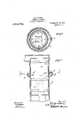
Referring'to the drawings, which accompany the specification, Figure l, is a transverse section, and Fig. 2 is a longitudinal section of the invention applied to the piston of an internal explosive engine, the various valve mechanisms and other parts, which are not part of this invention, being omitted from the drawings. Fig.3 is a longitudinal section, partly broken, showing a tumbling chamber applied to the wall of the cylinder, and Fig. 4 is a transverse section on the irregular line 45-4 of Fig. 3. Fig. 5 is a longitudinal'section showing a tumbling chamber on the piston and on the cylinder of an engine.
Referring to Figs. 1 and 2, the piston A, B, is of the-usual construction. In the periphery of said piston, A is the tumbling chamber d, which is preferably a peripheral groove or recess around said piston. As hereinbefore stated, said tumbling chamber'constitutes a chamber'for granular or powdered non-fluid lubricating substance, and I prefer to connect said tumbling chamber with the reservoir f by passages g. Said reservoir f is closed by any suitable closure,
as screw cap h, and said chamber may be of any size and shape, and larger or smaller than indicated in said Fig. 2, and located at any convenient place in said piston A. The wall of saidtumbling chamber d is prefe'rably inclined or curved in cross section to aid in forcing or wedging the particles of the lubricating substance against the wall" of cylinder C as said piston A reciprocates. Said tumbling chamber will be preferably filled only tosuch degree that the particles of said substance are more or less mobile in said tumbling chamber, and, as said piston reciprocates, certain of said particles will be pressed into contact with the wall of said cylinder C, and the attrition of said particles with said wall and with'each other, as also with the wall of said tumbling cham her, will grind said particles, and there will be reduced a fine film of the substance of said particles all over the wall ofsaid cylinder within thelimits of the stroke of said the inner side of said wall,'and wlth curved or sloping walls to aid in forcing or wedg-= ing the particles of the lubricant against. the
piston-A, A'J Said tumbling chamber at is preferablyconnected with a reservoir 7) for the lubricating substance, by ports 0. There may be one .or more reservoirs for the lubrivided with the tumbling chamber d in the piston A, A, and with the tumbling cham-' ber d on the wall of the cylinder C, the arcatmg substance, and the said reservoir or reservoirs are preferably, but not necessarily, formed in a boss or bosses integral with said cylinder C. One or more suitable orifices, closed by any suitable closures g ma'y be provided for filling said reservoir or reservoirs. It will be clear from the descrip tion and explanations hereinbefore given, that as the piston .reciprocates the attrition of the particles on each other, on the walls of the tumbling chamber 03' and on the surface of the piston will resultin applying a thin coating or film of the lubricating substance to the piston and cylinder wall,
: ,whereby excellent lubrication will be attained, and it will also be evident that the amount of lubrication will be automatically regulated according to the work done by the engine.
Referring to Fig. 5, the engine is prorangement of said. tumbling chambers, and
their connection with'their respective reservoirs being preferably as hereinbefore described in connection with Figs. 1 and 2, and with Figs. 3 and 4. The operation of the devices Will be clear from the explanaw tions hereinbefore given. It-Will be evident that the tumbling chambers may be used-without the reservoirs,
since the tumbling chambers contain suffiy cient lubricating material to properlylubricate the engine for considerable spaces of time, and claims are therefore hereinafter inserted to cover the invention both with and without reservoirs.
Now having described my improvements,
I claim as my invention:
1. In combination with a piston en 'ne, 8. tumbling chamber containing loose an movable particles of non-fluid lubricating material adapted to be tumbled about b the movements ofthe piston, substantial y as described. I v
2. The combination withthe cylinder and 'piston of an en 'ine, of a tumbling chamber and loose movable particles of non-fluid lubricant therein adapted to be tumbled about by the movement of said piston, and said tumbling chamber having walls adapted to inducetumbling motions in the particles of said lubricating material, substantially as described.
3. The combination in an engine of a cylinder and piston, a tumbling chamber in said piston, and a reservoir for non-fluid lubricant operatively connected with said tumbling chamber, substantially. as described.
4. The combination with a piston and cylinder, of a tumbling chamber, a reservoir for non-fluid lubricant operatively connected with said tumbling chamber, and a closure for said reservoir, substantially as described.
5. The combination with a piston and cylinder, of'a tumbling chamber in the cylinder, a reservoir for non-fluid lubricant operatively connected with said tumbling chamber, and a closure for said reservoir, substantially as described.
6. The combination with a piston and a cylinder of tumbling chambers on said piston and cylinder adapted to contain nonfluid lubricant, and having walls adapted to induce motion in the particles of said lubricant, substantialy as described. 7. The combination with a piston and a cylinder of lubricating chambers on said piston and cylinders, having walls adapted to induce tumbling motion 1n the particles of'the lubricating material, and reservoirs for non-fluid lubricating material operatively connected with said chambers, substantially as described.
Signed at New York city, in the county of New York and State of New York this I 23d day of. February A. D. 1911.
CHARLES S. BAVIER. Witnesses v G. W. HorkINs, WALTER Y. .I-IARRIs.
Priority Applications (1)
| Application Number | Priority Date | Filing Date | Title |
|---|---|---|---|
| US61161611A US1014744A (en) | 1911-03-01 | 1911-03-01 | Lubricating device. |
Applications Claiming Priority (1)
| Application Number | Priority Date | Filing Date | Title |
|---|---|---|---|
| US61161611A US1014744A (en) | 1911-03-01 | 1911-03-01 | Lubricating device. |
Publications (1)
| Publication Number | Publication Date |
|---|---|
| US1014744A true US1014744A (en) | 1912-01-16 |
Family
ID=3083050
Family Applications (1)
| Application Number | Title | Priority Date | Filing Date |
|---|---|---|---|
| US61161611A Expired - Lifetime US1014744A (en) | 1911-03-01 | 1911-03-01 | Lubricating device. |
Country Status (1)
| Country | Link |
|---|---|
| US (1) | US1014744A (en) |
Cited By (3)
| Publication number | Priority date | Publication date | Assignee | Title |
|---|---|---|---|---|
| US3204536A (en) * | 1963-11-18 | 1965-09-07 | Taylor William Raymond | Renewable piston |
| US4005763A (en) * | 1975-03-19 | 1977-02-01 | Wallis Bernard J | Lubricating means for gas-operated cylinders |
| US4771758A (en) * | 1985-04-01 | 1988-09-20 | Utec B.V. | Air weapon with air compression system having grooves for air transfer |
-
1911
- 1911-03-01 US US61161611A patent/US1014744A/en not_active Expired - Lifetime
Cited By (3)
| Publication number | Priority date | Publication date | Assignee | Title |
|---|---|---|---|---|
| US3204536A (en) * | 1963-11-18 | 1965-09-07 | Taylor William Raymond | Renewable piston |
| US4005763A (en) * | 1975-03-19 | 1977-02-01 | Wallis Bernard J | Lubricating means for gas-operated cylinders |
| US4771758A (en) * | 1985-04-01 | 1988-09-20 | Utec B.V. | Air weapon with air compression system having grooves for air transfer |
Similar Documents
| Publication | Publication Date | Title |
|---|---|---|
| US1014744A (en) | Lubricating device. | |
| US1579409A (en) | Engine piston and method of packing and lubricating the same | |
| US1147266A (en) | Emergency lubricating device. | |
| US1064542A (en) | Piston-support. | |
| US2140956A (en) | Pump | |
| US354936A (en) | Packing for piston-rods | |
| US1028426A (en) | Pump-plunger. | |
| RU1800211C (en) | Device for lubrication of friction surface | |
| US313964A (en) | swain | |
| US1869933A (en) | Seal for rotating shafts | |
| US1438546A (en) | Rod packing for hydraulic doorchecks | |
| US911891A (en) | Crank-box of gasolene-engines. | |
| US987962A (en) | Pump. | |
| US2168122A (en) | Piston pump | |
| US685922A (en) | Lubricator. | |
| US838380A (en) | Lubricating device. | |
| US810994A (en) | Connecting-rod for engines. | |
| US978611A (en) | Piston-rod stuffing-box and lubricator. | |
| US947449A (en) | Lubricating mechanism. | |
| US760686A (en) | Lubricating stuffing-box. | |
| US1572601A (en) | Friction material | |
| US690510A (en) | Lubricator for steam-engine pistons. | |
| US240214A (en) | Joseph l | |
| US368702A (en) | bischoff | |
| US1258901A (en) | Packing-box. |