US10145337B2 - Electrode ignition and control of electrically operated propellants - Google Patents
Electrode ignition and control of electrically operated propellants Download PDFInfo
- Publication number
- US10145337B2 US10145337B2 US15/197,421 US201615197421A US10145337B2 US 10145337 B2 US10145337 B2 US 10145337B2 US 201615197421 A US201615197421 A US 201615197421A US 10145337 B2 US10145337 B2 US 10145337B2
- Authority
- US
- United States
- Prior art keywords
- propellant
- electrodes
- ignition
- ignition surface
- electrically operated
- Prior art date
- Legal status (The legal status is an assumption and is not a legal conclusion. Google has not performed a legal analysis and makes no representation as to the accuracy of the status listed.)
- Active, expires
Links
- 239000003380 propellant Substances 0.000 title claims abstract description 216
- 230000003247 decreasing effect Effects 0.000 claims abstract description 18
- 238000002485 combustion reaction Methods 0.000 claims description 63
- 239000007800 oxidant agent Substances 0.000 claims description 16
- VLTRZXGMWDSKGL-UHFFFAOYSA-M perchlorate Inorganic materials [O-]Cl(=O)(=O)=O VLTRZXGMWDSKGL-UHFFFAOYSA-M 0.000 claims description 11
- VLTRZXGMWDSKGL-UHFFFAOYSA-N perchloric acid Chemical compound OCl(=O)(=O)=O VLTRZXGMWDSKGL-UHFFFAOYSA-N 0.000 claims description 11
- 239000002482 conductive additive Substances 0.000 claims description 9
- 230000008878 coupling Effects 0.000 claims 7
- 238000010168 coupling process Methods 0.000 claims 7
- 238000005859 coupling reaction Methods 0.000 claims 7
- 239000000654 additive Substances 0.000 abstract description 13
- 230000000996 additive effect Effects 0.000 abstract description 11
- 239000007789 gas Substances 0.000 description 41
- 238000010586 diagram Methods 0.000 description 10
- 239000000446 fuel Substances 0.000 description 6
- 238000012360 testing method Methods 0.000 description 6
- 238000009413 insulation Methods 0.000 description 5
- 239000011230 binding agent Substances 0.000 description 4
- 239000012141 concentrate Substances 0.000 description 4
- 238000009472 formulation Methods 0.000 description 4
- 239000000203 mixture Substances 0.000 description 4
- 230000007423 decrease Effects 0.000 description 3
- 230000005611 electricity Effects 0.000 description 3
- CRJZNQFRBUFHTE-UHFFFAOYSA-N hydroxylammonium nitrate Chemical compound O[NH3+].[O-][N+]([O-])=O CRJZNQFRBUFHTE-UHFFFAOYSA-N 0.000 description 3
- 239000000463 material Substances 0.000 description 3
- 238000005259 measurement Methods 0.000 description 3
- 239000007787 solid Substances 0.000 description 3
- GDDNTTHUKVNJRA-UHFFFAOYSA-N 3-bromo-3,3-difluoroprop-1-ene Chemical compound FC(F)(Br)C=C GDDNTTHUKVNJRA-UHFFFAOYSA-N 0.000 description 2
- 230000008033 biological extinction Effects 0.000 description 2
- 239000011248 coating agent Substances 0.000 description 2
- 238000000576 coating method Methods 0.000 description 2
- 239000007788 liquid Substances 0.000 description 2
- 239000002184 metal Substances 0.000 description 2
- 238000013459 approach Methods 0.000 description 1
- QVGXLLKOCUKJST-UHFFFAOYSA-N atomic oxygen Chemical compound [O] QVGXLLKOCUKJST-UHFFFAOYSA-N 0.000 description 1
- 230000008859 change Effects 0.000 description 1
- 238000004891 communication Methods 0.000 description 1
- 238000013461 design Methods 0.000 description 1
- 230000000694 effects Effects 0.000 description 1
- 230000001747 exhibiting effect Effects 0.000 description 1
- 239000012212 insulator Substances 0.000 description 1
- 150000002500 ions Chemical class 0.000 description 1
- 238000000034 method Methods 0.000 description 1
- 238000012544 monitoring process Methods 0.000 description 1
- 239000001301 oxygen Substances 0.000 description 1
- 229910052760 oxygen Inorganic materials 0.000 description 1
- 239000004033 plastic Substances 0.000 description 1
- 239000000843 powder Substances 0.000 description 1
- 230000008569 process Effects 0.000 description 1
- 230000031070 response to heat Effects 0.000 description 1
- 238000012546 transfer Methods 0.000 description 1
Images




Classifications
-
- F—MECHANICAL ENGINEERING; LIGHTING; HEATING; WEAPONS; BLASTING
- F02—COMBUSTION ENGINES; HOT-GAS OR COMBUSTION-PRODUCT ENGINE PLANTS
- F02K—JET-PROPULSION PLANTS
- F02K9/00—Rocket-engine plants, i.e. plants carrying both fuel and oxidant therefor; Control thereof
- F02K9/08—Rocket-engine plants, i.e. plants carrying both fuel and oxidant therefor; Control thereof using solid propellants
- F02K9/26—Burning control
-
- B—PERFORMING OPERATIONS; TRANSPORTING
- B60—VEHICLES IN GENERAL
- B60R—VEHICLES, VEHICLE FITTINGS, OR VEHICLE PARTS, NOT OTHERWISE PROVIDED FOR
- B60R21/00—Arrangements or fittings on vehicles for protecting or preventing injuries to occupants or pedestrians in case of accidents or other traffic risks
- B60R21/02—Occupant safety arrangements or fittings, e.g. crash pads
- B60R21/16—Inflatable occupant restraints or confinements designed to inflate upon impact or impending impact, e.g. air bags
- B60R21/26—Inflatable occupant restraints or confinements designed to inflate upon impact or impending impact, e.g. air bags characterised by the inflation fluid source or means to control inflation fluid flow
- B60R21/264—Inflatable occupant restraints or confinements designed to inflate upon impact or impending impact, e.g. air bags characterised by the inflation fluid source or means to control inflation fluid flow using instantaneous generation of gas, e.g. pyrotechnic
-
- F—MECHANICAL ENGINEERING; LIGHTING; HEATING; WEAPONS; BLASTING
- F02—COMBUSTION ENGINES; HOT-GAS OR COMBUSTION-PRODUCT ENGINE PLANTS
- F02K—JET-PROPULSION PLANTS
- F02K9/00—Rocket-engine plants, i.e. plants carrying both fuel and oxidant therefor; Control thereof
- F02K9/94—Re-ignitable or restartable rocket- engine plants; Intermittently operated rocket-engine plants
-
- F—MECHANICAL ENGINEERING; LIGHTING; HEATING; WEAPONS; BLASTING
- F02—COMBUSTION ENGINES; HOT-GAS OR COMBUSTION-PRODUCT ENGINE PLANTS
- F02K—JET-PROPULSION PLANTS
- F02K9/00—Rocket-engine plants, i.e. plants carrying both fuel and oxidant therefor; Control thereof
- F02K9/95—Rocket-engine plants, i.e. plants carrying both fuel and oxidant therefor; Control thereof characterised by starting or ignition means or arrangements
-
- F—MECHANICAL ENGINEERING; LIGHTING; HEATING; WEAPONS; BLASTING
- F42—AMMUNITION; BLASTING
- F42C—AMMUNITION FUZES; ARMING OR SAFETY MEANS THEREFOR
- F42C19/00—Details of fuzes
- F42C19/08—Primers; Detonators
- F42C19/0819—Primers or igniters for the initiation of rocket motors, i.e. pyrotechnical aspects thereof
-
- B—PERFORMING OPERATIONS; TRANSPORTING
- B60—VEHICLES IN GENERAL
- B60R—VEHICLES, VEHICLE FITTINGS, OR VEHICLE PARTS, NOT OTHERWISE PROVIDED FOR
- B60R21/00—Arrangements or fittings on vehicles for protecting or preventing injuries to occupants or pedestrians in case of accidents or other traffic risks
- B60R21/02—Occupant safety arrangements or fittings, e.g. crash pads
- B60R21/16—Inflatable occupant restraints or confinements designed to inflate upon impact or impending impact, e.g. air bags
- B60R21/26—Inflatable occupant restraints or confinements designed to inflate upon impact or impending impact, e.g. air bags characterised by the inflation fluid source or means to control inflation fluid flow
- B60R2021/26029—Ignitors
Definitions
- This invention relates to electrically operated propellants, and more particularly to controlling the ignition conditions of the propellant to efficiently and controllably ignite, burn and consume the electrically operated propellants in a manner that is scalable to combust an increased propellant mass for larger gas generation systems.
- All propellants are a combination of oxidizer, fuel, binder and additives.
- the oxidizer provides oxygen required to burn the fuel.
- the binder provides a structural material to bind the fuel and oxidizer.
- the binder itself is a fuel. Additional fuel may or may not be required.
- Additives may be used for a variety of purposes including to assist curing of the propellant, to control the burn rate, etc.
- Propellant may be used for gas generators, rocket motors, air bags and the like. It is desirable that substantially all of the propellant is or can be consumed.
- Solid rocket motor (SRM) propellants are ignited thermally and burn vigorously to completion of the propellant. SRM propellants typically exhibit a designed burn rate and consume substantially all of the propellant. However, the burn rate cannot be independently controlled. Furthermore, once ignited, SRM propellants cannot be “turned off” except by a violent and uncontrolled depressurization.
- the most common oxidizer for SRM propellants is a solid ammonium perchlorate (AP). The resulting SRM propellant ignites in response to heat but is electrically inert.
- Electrically operated propellants are ignited by application of an electric input.
- a voltage is applied between parallel wires embedded in the propellant.
- the current density J must exceed an ignition threshold of the propellant to ignite and burn.
- the oxidizer is “ionic” in the sense of providing free-flowing ions necessary for electrical control.
- the burn rate of the propellant may be controlled via the electric input.
- Certain formulations of the propellant, and more specifically the oxidizer, allow combustion to be extinguished by interruption of the electric input as long as the chamber pressure remains less than a self-sustaining threshold pressure.
- the propellant may be reignited by reapplication of the electric input.
- Sawka's hydroxyl-ammonium nitrate (HAN) based propellant (U.S. Pat. No. 8,857,338) exhibits a threshold of about 150 psi.
- Villarreal's perchlorate-based propellant U.S. Pat. No. 8,950,329) can be configured to exhibit a threshold greater than 200, 500, 1.500 and 2,000 psi. These higher threshold pressures allow for more practical applications in which the combustion may be turned on and off at elevated chamber pressures.
- a challenge to achieve wide spread use is to provide an electrode configuration that provides for control of the burn rate and efficient consumption of substantially all of the propellant, and one that is scalable to combust greater propellant mass to support larger gas generation systems.
- U.S. Pat. No. 8,857,338 “Electrode Ignition and Control of Electrically Ignitable Materials” also discloses an apparatus for providing electrically initiated and/or controlled combustion of electrically ignitable propellants is provided.
- the apparatus includes a volume of electrically ignitable propellant (solid and/or liquid), which is capable of self-sustaining combustion, and two (or more) electrodes operable to ignite the propellant.
- the apparatus may further include a power supply and controller in electrical communication with the electrodes for supplying a potential across the electrodes to initiate combustion of the propellant and/or control the rate of combustion of the propellant. For instance, by increasing or decreasing the power and current supplied through the propellant the rate of combustion may be varied.
- the electrodes are in electrical contact with the electrically ignitable propellant and are supplied a direct current, which may cause combustion of the electrically ignitable propellant at the contact location of the positive electrode with the electrically ignitable propellant.
- the electrodes are supplied an alternating current, which may initiate nearly simultaneously combustion of the electrically ignitable propellant at the contact locations of the electrodes with the electrically ignitable propellant.
- one or more of the electrodes may include an insulator material insulating a portion of the electrode from the electrically ignitable propellant (which may burn away with combustion of the propellant).
- a center insulated wire electrode is positioned along the axis of a cylindrical electrode in a coaxial configuration around the propellant ( FIGS. 1 a -1 b ). As combustion of the propellant is initiated, the insulation burns away and the propellant regresses along the axis.
- parallel plate electrodes are positioned to either side of the propellant ( FIGS. 3 a -3 b ).
- one of the parallel plate electrodes is insulated to produce combustion of the propellant to spread across the gain-end to the outer cathode. The combustion of the propellant propagates to the left along the axis of the structure, in a generally uniform manner as illustrated.
- both of the plate electrodes are un-insulated.
- the propellant is broadly ignited along much of or the entire length of the positive electrode.
- the present invention provides electrode ignition and control of electrically operated propellants that efficiently consumes the available propellant and is scalable to combust increased propellant mass for larger gas generation systems.
- the contour of the ignition surface is designed and built to match the contour of current lines between the electrodes. At least 95% of the available mass of the propellant is consumed. If combustion is interrupted, that means at least 95% of the available mass up to the point of extinguishment.
- a gas generation system may be configured to consume at least 10 grams, 100 grams, 1,000 grams or more of electrically operated propellant.
- the electrically operated propellant comprises an ionic perchlorate-based oxidizer such that the propellant has a self-sustaining threshold pressure of at least 500 psi at which the propellant once ignited by the electrical input cannot be extinguished and below which the propellant can be extinguished by interruption of the electrical input. Combustion may be turned off and on per application requirements.
- the self-sustaining threshold may be 1,000, 1,500, 2,000 psi or higher.
- the pair of electrodes are angled at greater than 0 degrees and less than 90 degrees with respect to each other such that a cross-section of the propellant between the electrodes increases in area along the axis normal to the ignition surface. In another embodiment, the angle between the electrodes is between 20 and 60 degrees.
- the electrodes may be symmetric or asymmetric about the axis.
- a conducting or non-conducting additive is added to the electrically operated propellant.
- concentration of the additive follows a gradient along the axis normal to the ignition surface.
- a conductive additive may be a metal powder and a non-conducting additive may be an electrical insulating plastic. This produces the decreasing gradient in current density J along the axis.
- the electrodes may be configured as parallel plate or angled electrodes.
- each of the electrodes comprises a plurality of sub-electrodes.
- a network of relays and switches selectively activate one pair of sub-electrodes at a time to propagate the electrical signal along the axis.
- the current density J constitutes a maximum pulse at the activated pair of sub-electrodes followed by a null current density at the following un-activated pairs of sub-electrodes.
- the pulse propagates down the axis to ignite the ignition surface as the propellant regresses.
- This approach may be combined with either or both of the angled electrodes and conductive/non-conductive additive.
- the gas generation system is configured as a radial burning rocket motor.
- An even number of four or more electrodes is spaced radially about a longitudinal axis of the cylindrical rocket fuselage embedded in the electrically operated propellant.
- Each adjacent pair of said four or more electrodes is angled at greater than 0 degrees and less than 90 degrees with respect to each other such that a cross-section of the propellant between the electrodes increases in area along an axis normal to an ignition surface that regresses radially along the axis away from the longitudinal axis.
- the gas generation system is configured as an end-burning rocket motor.
- the electrodes extend axially along the length of the longitudinal axis of the cylindrical rocket fuselage.
- the electrodes may, for example, be concentric cylindrical electrodes or parallel electrodes.
- a conducting or non-conducting additive is added to the electrically operated propellant to create a gradient current density J that is maximum at an open end of the rocket motor.
- An electrical signal ignites the ignition surface at the open end, which burns and regresses along the longitudinal axis.
- the gas generation system is configured with a conductive coating between the electrically operated propellant and the electrodes. This conductive coating will aid in the efficient transfer of the current and provide for mechanical bonding of the electrically operated propellant to the electrodes.
- the gas generation system is configured as an airbag deployment system.
- the electrically operated propellant suitably comprises an ionic perchlorate-based oxidizer that exhibits a self-sustaining threshold of at least 1,000 psi. Combustion of the electrically operated propellant generates pressured gas that is exhausted from the chamber to inflate the airbag. Chamber pressures remain below the self-sustaining threshold such that interruption of the electrical input extinguishes combustion to control the inflation of the airbag.
- FIG. 1 is a plot of current density J along an axis normal to the ignition surface exhibiting a decreasing gradient
- FIG. 2 is a plot of the approximately constant current density J across the contour of the ignition surface
- FIGS. 3 a -3 c are plots of current density J as the ignition surface regresses along the axis;
- FIG. 4 is diagram of the current lines between a pair of parallel wire electrodes embedded in electrically operated propellant
- FIGS. 5 a and 5 b are different views of the current lines between a center electrode and a cylindrical electrode in a coaxial configuration in which is embedded electrically operated propellant;
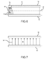
- FIG. 6 is a diagram of the current lines between a pair of parallel plate electrodes in which one plate is insulated and burns away as the propellant is consumed;
- FIG. 7 is a diagram of the current lines between a pair of parallel plate electrodes
- FIG. 8 is a diagram of an embodiment of a gas generation system
- FIG. 9 is a diagram of an embodiment of angled electrodes that create a current density gradient along an axis normal to an ignition surface
- FIG. 10 is a diagram of an embodiment in which the electrically operated propellant includes an additive that creates a current density gradient along an axis normal to an ignition surface;
- FIG. 11 is a diagram of an embodiment of segmented parallel electrodes that are switched to propagate an electrical input through the electrically operated propellant
- FIG. 12 is a diagram of a radial burning rocket motor with an even number of angled electrodes positioned radially about the rocket motor;
- FIG. 13 is a diagram an end burning rocket motor
- FIG. 14 is a diagram of a gas generation system using a radial configuration of angled electrodes to inflate an airbag.
- FIGS. 1, 2 and 3 a - 3 c different configurations of electrode structures and electrically operable propellant in a gas generation system must provide an ignition condition at an ignition surface between a pair of electrodes that satisfies three criteria to effectively control burn rate, efficiently consume the available propellant and do so in a manner that is scalable to greater propellant mass.
- a current density J 10 along an axis 12 normal to the ignition surface exhibits a decreasing gradient.
- the gradient can be produced by, for example, angling and/or segmenting the electrodes and or adding a gradient concentration of a conducting/non-conducting additive to the propellant.
- the gradient forces combustion to be initiated at the ignition surface having the maximum current density and to regress along the axis normal to the ignition surface in the direction of the decreasing gradient.
- a current density J 20 across the ignition surface 22 is approximately constant. If this condition is satisfied, the entire ignition surface should ignite. Otherwise, the propellant will only ignite at or near the point of maximum current density J, typically at the surface of one of the electrodes or near the middle of the two electrodes, which hinders the ability to control the burn rate and leaves a lot of propellant unconsumed.
- the contour of the ignition surface is designed and built to match the contour of current lines between the electrodes. To do this, the current lines are calculated for a given electrode configuration and electrically operated propellant. The contour of the ignition surface is then designed to match the contour of the current lines. Contouring the ignition surface can change the current lines.
- the process may be iterated until any effects are negligible.
- the contour of the ignition surface as built matches the field lines to the limits of manufacturability. In theory, the design of the contour should exactly match the current lines and the contour as built should exhibit less than a 2% deviation. Satisfying this criterion, substantially all (>95%) of the ignition surface should be consumed as the ignition surface regresses.
- the current density J 30 at the exposed ignition surface must exceed the ignition threshold 34 to combust.
- the current density J at any cross-section in the bulk of the propellant may or may not exceed ignition threshold 34 . Even if current density J in the bulk exceeds the ignition threshold because the current density J exhibits a decreasing gradient along the axis normal to the ignition surface per the first criterion, ignition will initiate at the exposed ignition surface corresponding to the maximum current density J.
- Configurations that satisfy all criteria and particularly the second criterion are critical to scalability, efficiency and controllability.
- For propellant masses of at least 10 grams, 100 grams, 1,000 grams or more establishing and maintaining the gradient is required to concentrate the available power such that the current density J at the ignition surface exceeds the ignition threshold to sustain ignition.
- the spacing between electrodes increases. Matching the contour of the ignition surface to the current lines such that the current density J is approximately constant across the surface is required to ignite and combust substantially all of the ignition surface.
- a pair of parallel wires 40 and 42 are embedded in an electrically operated propellant 44 .
- Current flows from the positive electrode, wire 42 , to the negative electrode, wire 40 , along current lines 46 .
- the spacing of current lines 46 dictates the current density J. The closer the current lines 46 , the higher the current density J. In this configuration, the current density J is the highest at wire 40 .
- the current density J is uniform along an axis into the propellant parallel to the wires. Testing has demonstrated that application of an electrical input to the wires creates an ignition condition in which the propellant at the surface of wire 40 is ignited and the amount of propellant that combusts is very small. The propellant burns for only a small distance away from wire 40 and extinguishes.
- the parallel wires provide neither the current density J gradient along the axis nor the approximately constant current density J across an ignition surface required to ignite an ignition surface between the wires and cause the ignition surface to regress along the axis.
- a coaxial electrode configuration includes a cylindrical positive electrode 50 and a negative electrode 52 along the axis 54 of the positive electrode.
- Current flows from positive electrode 50 to negative electrode 52 along current lines 56 .
- the current density is a maximum at the concentration of current lines 56 at negative electrode 52 .
- the negative electrode 52 is provide with an insulative sleeve 58 that serves to further concentrate the current lines 56 at an exposed end 60 of negative electrode 52 .
- Testing has demonstrated that application of an electrical input to the coaxial electrode configuration creates an ignition condition in which the propellant at an ignition surface 62 at end 60 ignites. This burns back the insulative sleeve 58 allowing ignition surface 62 to regress along axis 54 .
- the coaxial electrode structure creates a current density J that is maximum at the center and falls off as 1/radius. This non-uniformity is further exacerbated by the insulative sleeve that concentrates the field lines at the center. For coaxial electrode structures on the order of 1 ⁇ 8′′ in diameter, the electrical input is sufficient to overcome this non-uniformity and ignite the entire ignition surface. However as the diameter increases the current density J is too low to ignite and combustion is limited to a small area around the center electrode.
- a parallel plate electrode configuration includes a positive plate electrode 70 and a negative plate electrode 72 with a bare end 74 and insulation 76 . Similar to the coaxial configuration, the insulation concentrates current lines 78 at the bare end 74 of negative plate electrode 72 .
- Testing has demonstrated that application of an electrical input to the parallel plate configuration creates an ignition condition in which the propellant at an ignition surface 80 at end 74 ignites. This burns back insulation 76 allowing ignition surface 80 to regress along an axis 82 between the plates. However, the testing demonstrated that this only holds for very small amounts of propellant, less than 1 gram, and very small electrodes spaces, about 1 ⁇ 8′′ between the parallel plates. If the spacing is scaled up to accommodate larger propellant mass, the propellant ignites only at or near the insulated negative plate electrode 72 leaving much of the propellant unconsumed.
- the parallel plate structure itself would creates a current density J was uniform across the ignition surface.
- concentration of the current lines at the bare end of the negative plate electrode 72 produces a non-uniformity in the current density J, which peaks at the negative plate electrode 72 and falls off towards positive plate electrode 70 .
- the electrical input is sufficient to overcome this non-uniformity and ignite the entire ignition surface.
- the plate spacing increases the current density J is too low to ignite and combustion is limited to a small area near negative plate electrode 72 .
- a parallel plate electrode configuration includes a positive plate electrode 90 and a negative plate electrode 92 . Because neither plate is insulated, current lines 94 match the contour of a desired ignition surface such that the current density J is constant across the ignition surface. However, the current density J is also constant throughout the bulk of the electrically operable propellant 96 . This requires a lot of current, i.e., power, to raise the current density J above the ignition threshold to initiate combustion. Furthermore, if the power is sufficient to exceed the ignition threshold testing has demonstrated that the bulk of the electrically operated propellant will all ignite at once. This configuration, without the insulation, does not create a preferential ignition surface to ignite and regress in a controlled manner along an axis between the plates.
- the present invention provides different configurations of electrode structures and electrically operable propellant in a gas generation system that provide an ignition condition at an ignition surface between a pair of electrodes that satisfies the three criteria of current density J that exhibits a decreasing gradient along an axis normal to an ignition surface, is constant across the ignition surface and exceeds an ignition threshold at the ignition surface.
- the configurations are useful for all varieties of electrical operated propellants.
- the configurations may be used with electrical operated propellants that exhibit no ability to be extinguished, propellants with a HAN-based oxidizer that exhibit a low self-sustaining threshold of about 150 psi, propellants with a perchlorate-based oxidizer that exhibit self-sustaining thresholds above 500, 1,000, 1,500 or event 2,000 psi.
- U.S. Pat. No. 8,950,329 which details the formulation of the perchlorate-based electrically operated propellant is hereby incorporated by reference.
- the gas generation systems may be configured to simply burn the entire electrically operated propellant to extinction at a given burn rate, to control the burn rate and burn to extinction, to turn the combustion on and off, and back on again.
- An exemplary electrically operated propellant includes a metal-based fuel of approximate 5 to 30 percent of the mass of the propellant, a liquid perchlorate-based ionic oxidizer of approximately 50 to 90 percent of the mass and a binder of approximately 10 to 30 percent of the mass.
- a gas generation system 100 includes a gas generator 102 , a controller 104 and a power source 106 such as a battery, generator or the like.
- Gas generator 102 is usable to provide a source of pressurized gas for a rocket motor, attitude and control systems, gas compressors, ignition systems, airbag inflation systems and the like.
- Gas generator 102 includes a combustion chamber 108 having an electrically operated propellant 110 positioned therein. Two or more electrodes 112 extend into the electrically operated propellant 110 within the combustion chamber 112 . A nozzle 114 is coupled to combustion chamber 112 . Electrically operated propellant 110 includes a formulation that allows for the ignition and extinguishing of the propellant in a variety of conditions according to the application (and interruption of the application) of electricity through the electrodes 112 . For instance, the electrically operated propellant 110 is configured to ignite with the application of voltage across the electrodes 112 .
- the electrically operated propellant 110 is extinguished with the interruption of the voltage at a range of chamber pressures (e.g., from 500 psi to 2000 psi) less than the self-sustaining threshold pressure.
- the two or more electrodes 112 and electrically operated propellant 110 are configured to produce an ignition condition that satisfies the three criteria. Ignition and combustion of the electrically operated propellant 110 produces elevated chamber pressures. Gas is exhausted through nozzle 114 to generate high pressure/high velocity gas for a particular application.
- Controller 104 is shown as including in one example a generation module 120 (e.g., a flight module for a rocket or airbag inflation module for a vehicle).
- the generation module 120 is coupled with a voltage control module 122 and a power measurement module 124 .
- the generation module 120 is a flight module, and the flight module is configured to control the amount of thrust provided as part of a rocket motor. For instance, as ignition, extinguishing and throttling of thrust output from the gas generator 102 is desired, the flight module is configured to provide this control by way of management of the electrical output to the gas generator through control of the voltage control module 122 .
- the voltage control module 122 is coupled along the electrical circuit between the power source 106 and the gas generator 102 .
- the voltage control module 122 is in one example coupled with the power measurement module 124 .
- the power measurement module is configured to measure the output of the power source and thereby facilitate control and administration of the appropriate amount of electricity such as voltage, current or the like to the gas generator through the voltage control module.
- the generation module 120 includes one or more of an ignition module 130 to control the application of the electrical input to the electrically operated propellant via the electrodes, an extinguishing module 132 to interrupt the application of the electrical input to extinguish combustion, a throttling module 134 to vary the electrical input to increase or decrease the burn rate and a pressure monitoring module 134 to measure the chamber pressure to provide feedback to the other modulates to control ignition, extinguishment and throttling.
- an ignition module 130 to control the application of the electrical input to the electrically operated propellant via the electrodes
- an extinguishing module 132 to interrupt the application of the electrical input to extinguish combustion
- a throttling module 134 to vary the electrical input to increase or decrease the burn rate
- a pressure monitoring module 134 to measure the chamber pressure to provide feedback to the other modulates to control ignition, extinguishment and throttling.
- Each of these modules controls various corresponding functions of the gas generator 102 .
- an embodiment of an electrode configuration for a gas generator comprises a pair of plate electrodes 200 and 202 that are angled between 0 and 90 degrees, and more typically between 20 and 60 degrees, with respect to each other such that a cross section 204 of an electrically operated propellant 206 increases in area along an axis 208 normal to an ignition surface 210 .
- the increasing diameter of cross-section 204 creates a gradient in the current density J (in a given cross-section) that decreases along the axis.
- the applied electrical signal, conductivity of the electrically operated propellant and the angle of the pair of electrodes establish a current density J at the ignition surface that exceeds an ignition threshold.
- the ignition surface is contoured to match the contour of current lines 212 between the plate electrodes.
- the plate electrodes are “angled” (not parallel), the contour that matches the current lines is not flat. The amount of curvature is dictated by the angle between the plates.
- the current density J at a narrow end 214 will be the highest and will decrease along axis 208 to a lowest value at a wide end 216 .
- ignition surface 210 at narrow end 214 will ignite across substantially all of the surface and regress along axis 208 normal to the ignition surface. Unless the electrical signal is interrupted to extinguish combustion, combustion will continue along the axis to burn substantially all of the propellant.
- an embodiment of an electrode configuration for a gas generator comprises a pair of parallel plate electrodes 230 and 232 on either side of an electrically operated propellant 234 .
- a conducting or non-conductive additive 236 is added to the electrically operated propellant.
- the additive 236 has a gradient concentration along an axis 238 normal to an ignition surface 240 , which modifies the conductivity of the propellant to have a decreasing gradient along the axis, which in turn produces a current density J with a decreasing gradient along the axis.
- a conducting additive would have maximum concentration at the ignition surface decreasing along the axis.
- a non-conductive additive (as shown) would have a minimum concentration at the ignition surface increasing along the axis.
- the current lines 242 between the parallel plate electrodes 230 and 232 are normal to axis 238 and evenly spaced. Accordingly, the ignition surface has a flat contour to match the current lines.
- ignition surface 240 Upon application of an electrical input between the pair of plate electrodes 230 and 232 , ignition surface 240 will ignite across substantially all of the surface at the maximum current density J and regress along axis 238 normal to the ignition surface. Unless the electrical signal is interrupted to extinguish combustion, combustion will continue along the axis to burn substantially all of the propellant.
- an embodiment of an electrode configuration for a gas generator comprises a pair of parallel plate electrodes 250 and 252 on either side of an electrically operated propellant 253 .
- Each of the electrodes 250 and 252 comprises a plurality of sub-electrodes 254 a , 254 b , . . . and 256 a , 256 b , . . . .
- a network of relay 258 and switches 260 selectively activate one pair of sub-electrodes 254 a / 256 a , 254 b / 256 b . . .
- the decreasing gradient of current density J constitutes a pulse 262 at the activated pair of sub-electrodes followed by a null at the following unactivated pairs of sub-electrodes.
- the pulse 262 propagates down the axis 258 to ignite the ignition surface 261 as the propellant regresses.
- the same concept of using segmented electrodes and a network of relays and switches to propagate a pulse through the electrically operated propellant may be applied to angled electrodes or concentric electrodes.
- any two or more of the angled electrodes, non-conducting/conducting additive to the electrically operated propellant and segmented electrodes may be combined.
- Other configurations of electrode structures and propellant conductivity may be envisioned that satisfy the three criteria for efficient, controllable and scalable combustion of the electrically operated propellant.
- an embodiment of a radial burning rocket motor 300 comprises an even number of four or more electrodes 302 is spaced radially about a longitudinal axis 304 of a cylindrical rocket fuselage 306 and embedded in a electrically operable propellant 308 .
- Each adjacent pair of said four or more the electrodes is angled at greater than 20 degrees and less than 90 degrees with respect to each other such that a cross-section 310 of the propellant between the electrodes increases in diameter along an axis 312 normal to an ignition surface 314 that regresses radially along the axis 312 away from the longitudinal axis 304 .
- Field lines 316 extend from the positive electrodes to the negative electrodes. The resulting pressurized gas is exhausted through a nozzle to produce thrust.
- an embodiment of an end-burning rocket motor 400 comprises concentric circular electrodes 402 and 404 about a longitudinal axis 406 of a cylindrical rocket fuselage 408 , which extend the length of an electrically operable propellant 410 embedded between the inner and outer circular electrodes.
- Electrically operable propellant 408 is provided with an additive that varies its conductance to create a gradient current density that is a maximum at an ignition surface 412 at an end 414 of the rocket motor.
- Application of an electrical signal to the concentric circular electrodes ignites ignition surface 412 only at end 414 .
- the ignition surface 412 burns and regresses axially along longitudinal axis 404 to consume the electrically operable propellant.
- the resulting pressurized gas is exhausted through a nozzle to produce thrust.
- the electrodes may be configured as parallel plates with a rectangular cross-section.
- an embodiment of an airbag inflation system 500 includes a gas generation system 502 that uses an electrically operated propellant 508 within a combustion chamber 504 configured to pressurize the chamber and exhaust high-pressure gas through an opening 512 to inflate an airbag 513 .
- Opening 512 may be or may not be formed as a nozzle.
- the electrically operated propellant 508 includes a formulation (e.g., a perchlorate-based ionic oxidizer) that allows for the ignition and extinguishing of the propellant in a variety of conditions according to the application (and interruption of the application) of electricity a chamber pressures below a self-sustaining threshold pressure of at least 1,000 psi.
- Electrodes 510 are spaced radially about a longitudinal axis 515 and embedded in an electrically operable propellant 514 .
- Each adjacent pair of said four or more the electrodes is angled at greater than 20 degrees and less than 90 degrees with respect to each other such that a cross-section of the propellant between the electrodes increases in diameter along an axis normal to an ignition surface that regresses radially along the axis away from the longitudinal axis 515 .
- the electrodes alternate as + and ⁇ electrodes.
- the + electrodes are connected to an external positive electrode 522 and the ⁇ electrodes are connected to an external negative 524 for connection to a power supply.
- an electrical input is applied through positive and negative electrodes 522 and 524 to alternating electrodes 510 to produce a current density J at the interior ignition surface 520 between each pair of electrodes 510 that exceeds an ignition threshold.
- Each ignition surface ignites and regresses along axis normal to the ignition surface.
- the combustion of the electrically operated propellant generates pressured gas in combustion chamber 504 . Pressure levels in the chamber reaching more than 500 psi but never more than the self-sustaining threshold pressure. Pressurized gas I the chamber is exhausted through opening 512 to inflate airbag 513 .
- the electrical input is varied to vary a rate of combustion, hence varying the pressure levels in the chambers to control a pressure profile of the airbag.
- the electrical signal is interrupted to extinguish combustion of the propellant to control a total pressure impulse delivered to the airbag. Combustion may be turned on and off by application and interruption of the electrical signal
Landscapes
- Engineering & Computer Science (AREA)
- General Engineering & Computer Science (AREA)
- Mechanical Engineering (AREA)
- Chemical & Material Sciences (AREA)
- Combustion & Propulsion (AREA)
- Physics & Mathematics (AREA)
- Fluid Mechanics (AREA)
- Feeding, Discharge, Calcimining, Fusing, And Gas-Generation Devices (AREA)
- Air Bags (AREA)
Priority Applications (4)
| Application Number | Priority Date | Filing Date | Title |
|---|---|---|---|
| US15/197,421 US10145337B2 (en) | 2016-06-29 | 2016-06-29 | Electrode ignition and control of electrically operated propellants |
| ES17800960T ES2904790T3 (es) | 2016-06-29 | 2017-06-09 | Sistema generador de gas |
| PCT/US2017/036803 WO2018022203A1 (en) | 2016-06-29 | 2017-06-09 | Electrode ignition and control of electrically operated propellants |
| EP17800960.1A EP3433567B1 (de) | 2016-06-29 | 2017-06-09 | Gasgeneratorsystem |
Applications Claiming Priority (1)
| Application Number | Priority Date | Filing Date | Title |
|---|---|---|---|
| US15/197,421 US10145337B2 (en) | 2016-06-29 | 2016-06-29 | Electrode ignition and control of electrically operated propellants |
Publications (2)
| Publication Number | Publication Date |
|---|---|
| US20180003130A1 US20180003130A1 (en) | 2018-01-04 |
| US10145337B2 true US10145337B2 (en) | 2018-12-04 |
Family
ID=60388111
Family Applications (1)
| Application Number | Title | Priority Date | Filing Date |
|---|---|---|---|
| US15/197,421 Active 2037-04-11 US10145337B2 (en) | 2016-06-29 | 2016-06-29 | Electrode ignition and control of electrically operated propellants |
Country Status (4)
| Country | Link |
|---|---|
| US (1) | US10145337B2 (de) |
| EP (1) | EP3433567B1 (de) |
| ES (1) | ES2904790T3 (de) |
| WO (1) | WO2018022203A1 (de) |
Families Citing this family (2)
| Publication number | Priority date | Publication date | Assignee | Title |
|---|---|---|---|---|
| US9457761B2 (en) * | 2014-05-28 | 2016-10-04 | Raytheon Company | Electrically controlled variable force deployment airbag and inflation |
| CN114991999B (zh) * | 2022-05-31 | 2025-02-11 | 西安近代化学研究所 | 一种不含烟火剂的电点火装置 |
Citations (15)
| Publication number | Priority date | Publication date | Assignee | Title |
|---|---|---|---|---|
| US5711546A (en) * | 1994-03-18 | 1998-01-27 | Oea, Inc. | Hybrid inflator with coaxial chamber |
| US6474684B1 (en) * | 1997-04-24 | 2002-11-05 | Talley Defense Systems, Inc. | Dual stage inflator |
| US20040050283A1 (en) * | 2002-09-12 | 2004-03-18 | Sami Daoud | Dual-stage gas generator utilizing eco-friendly gas generant formulation for military applications |
| US20060011276A1 (en) * | 2002-04-24 | 2006-01-19 | Charles Grix | Electrically controlled solid propellant |
| US7337856B2 (en) * | 2003-12-02 | 2008-03-04 | Alliant Techsystems Inc. | Method and apparatus for suppression of fires |
| US20080087003A1 (en) | 2002-01-16 | 2008-04-17 | Michael Dulligan | Methods of controlling solid propellant ignition, combustion, and extinguishment |
| US20080134924A1 (en) | 2004-12-17 | 2008-06-12 | Sawka Wayne N | Controllable digital solid state cluster thrusters for rocket propulsion and gas generation |
| US7404288B2 (en) * | 2004-10-28 | 2008-07-29 | Spacedev, Inc. | High propulsion mass fraction hybrid propellant system |
| US8857338B2 (en) | 2008-05-16 | 2014-10-14 | Digital Solid State Propulsion Llc | Electrode ignition and control of electrically ignitable materials |
| US8950329B2 (en) | 2012-12-24 | 2015-02-10 | Raytheon Company | Electrically operated propellants |
| US20150343988A1 (en) * | 2014-05-28 | 2015-12-03 | Raytheon Company | Electrically controlled variable force deployment airbag and inflation |
| US20170253536A1 (en) * | 2016-03-01 | 2017-09-07 | Raytheon Company | Solid propellant with integral electrodes, and method |
| US20170284339A1 (en) * | 2016-04-05 | 2017-10-05 | Raytheon Company | Thruster with segmented propellant |
| US20180051657A1 (en) * | 2016-08-18 | 2018-02-22 | Raytheon Company | Microwave ignition of electrically operated propellants |
| US20180058377A1 (en) * | 2016-08-25 | 2018-03-01 | Raytheon Company | Actuator structure and method of ignition of electrically operated propellant |
-
2016
- 2016-06-29 US US15/197,421 patent/US10145337B2/en active Active
-
2017
- 2017-06-09 ES ES17800960T patent/ES2904790T3/es active Active
- 2017-06-09 EP EP17800960.1A patent/EP3433567B1/de active Active
- 2017-06-09 WO PCT/US2017/036803 patent/WO2018022203A1/en not_active Ceased
Patent Citations (16)
| Publication number | Priority date | Publication date | Assignee | Title |
|---|---|---|---|---|
| US5711546A (en) * | 1994-03-18 | 1998-01-27 | Oea, Inc. | Hybrid inflator with coaxial chamber |
| US6474684B1 (en) * | 1997-04-24 | 2002-11-05 | Talley Defense Systems, Inc. | Dual stage inflator |
| US20080087003A1 (en) | 2002-01-16 | 2008-04-17 | Michael Dulligan | Methods of controlling solid propellant ignition, combustion, and extinguishment |
| US20060011276A1 (en) * | 2002-04-24 | 2006-01-19 | Charles Grix | Electrically controlled solid propellant |
| US20040050283A1 (en) * | 2002-09-12 | 2004-03-18 | Sami Daoud | Dual-stage gas generator utilizing eco-friendly gas generant formulation for military applications |
| US7337856B2 (en) * | 2003-12-02 | 2008-03-04 | Alliant Techsystems Inc. | Method and apparatus for suppression of fires |
| US7404288B2 (en) * | 2004-10-28 | 2008-07-29 | Spacedev, Inc. | High propulsion mass fraction hybrid propellant system |
| US8464640B2 (en) | 2004-12-17 | 2013-06-18 | Digital Solid State Propulsion Llc | Controllable digital solid state cluster thrusters for rocket propulsion and gas generation |
| US20080134924A1 (en) | 2004-12-17 | 2008-06-12 | Sawka Wayne N | Controllable digital solid state cluster thrusters for rocket propulsion and gas generation |
| US8857338B2 (en) | 2008-05-16 | 2014-10-14 | Digital Solid State Propulsion Llc | Electrode ignition and control of electrically ignitable materials |
| US8950329B2 (en) | 2012-12-24 | 2015-02-10 | Raytheon Company | Electrically operated propellants |
| US20150343988A1 (en) * | 2014-05-28 | 2015-12-03 | Raytheon Company | Electrically controlled variable force deployment airbag and inflation |
| US20170253536A1 (en) * | 2016-03-01 | 2017-09-07 | Raytheon Company | Solid propellant with integral electrodes, and method |
| US20170284339A1 (en) * | 2016-04-05 | 2017-10-05 | Raytheon Company | Thruster with segmented propellant |
| US20180051657A1 (en) * | 2016-08-18 | 2018-02-22 | Raytheon Company | Microwave ignition of electrically operated propellants |
| US20180058377A1 (en) * | 2016-08-25 | 2018-03-01 | Raytheon Company | Actuator structure and method of ignition of electrically operated propellant |
Also Published As
| Publication number | Publication date |
|---|---|
| US20180003130A1 (en) | 2018-01-04 |
| EP3433567B1 (de) | 2021-11-10 |
| WO2018022203A1 (en) | 2018-02-01 |
| ES2904790T3 (es) | 2022-04-06 |
| EP3433567A1 (de) | 2019-01-30 |
Similar Documents
| Publication | Publication Date | Title |
|---|---|---|
| US20180058377A1 (en) | Actuator structure and method of ignition of electrically operated propellant | |
| JP4908629B2 (ja) | 単元推進薬を用いるロケットエンジン用の電解式点火器 | |
| US10359189B2 (en) | Electrodynamic combustion control with current limiting electrical element | |
| JP4908628B2 (ja) | 液体推進薬を用いるロケットエンジン用の電解式点火器 | |
| US20150047526A1 (en) | Electrode ignition and control of electrically ignitable materials | |
| WO2008060255A3 (en) | Electrically controlled extinguishable solid propellant motors | |
| US10145337B2 (en) | Electrode ignition and control of electrically operated propellants | |
| CN113187622B (zh) | 一种电-化学混合动力空间推力器 | |
| CN113123901A (zh) | 基于电阻加热及燃烧室高温引燃的离子推进剂电点火方法 | |
| CN114718765A (zh) | 一种用于微纳卫星的电弧点火器 | |
| EP3500545B1 (de) | Mikrowellenzündung elektrisch betriebener treibstoffe | |
| JP2016536520A (ja) | 電気的に点火され、スロットル調整された焦電性推進剤ロケットエンジン | |
| CN115822814A (zh) | 同轴环形多电极电控固体推力器 | |
| KR102633337B1 (ko) | 고체에어로졸 소화기용 기동장치 | |
| US3032978A (en) | Magnetic compression engine | |
| WO1997036463A1 (fr) | Source de molecules neutres rapides | |
| JP3136903B2 (ja) | 熱電池 | |
| JPH0670407B2 (ja) | プラズマジェット生成法とプラズマ発生器 | |
| US20260096005A1 (en) | Plasma generation system with plasma generator having short electrode protrusion and/or disconnectable portion | |
| CA2220920A1 (en) | Method and apparatus for blasting hard rock | |
| CN121539405A (zh) | 一种微小卫星用化电混合模式固体推进装置 | |
| CN121775776A (zh) | 一种电激发电路、装置、固体化学氧气发生器及供氧系统 | |
| JPH06243878A (ja) | 熱電池 | |
| Pavlov et al. | A three-point ignition of ablative pulse discharge in vacuum |
Legal Events
| Date | Code | Title | Description |
|---|---|---|---|
| AS | Assignment |
Owner name: RAYTHEON COMPANY, MASSACHUSETTS Free format text: ASSIGNMENT OF ASSIGNORS INTEREST;ASSIGNORS:SUMMERS, MATT H.;VILLARREAL, JAMES K.;LANGHENRY, MARK T.;AND OTHERS;SIGNING DATES FROM 20160627 TO 20160629;REEL/FRAME:039046/0907 |
|
| STCF | Information on status: patent grant |
Free format text: PATENTED CASE |
|
| MAFP | Maintenance fee payment |
Free format text: PAYMENT OF MAINTENANCE FEE, 4TH YEAR, LARGE ENTITY (ORIGINAL EVENT CODE: M1551); ENTITY STATUS OF PATENT OWNER: LARGE ENTITY Year of fee payment: 4 |