US10145144B1 - Electric door lock - Google Patents
Electric door lock Download PDFInfo
- Publication number
- US10145144B1 US10145144B1 US15/792,554 US201715792554A US10145144B1 US 10145144 B1 US10145144 B1 US 10145144B1 US 201715792554 A US201715792554 A US 201715792554A US 10145144 B1 US10145144 B1 US 10145144B1
- Authority
- US
- United States
- Prior art keywords
- cover
- circuit board
- receiving room
- wall
- inner cover
- Prior art date
- Legal status (The legal status is an assumption and is not a legal conclusion. Google has not performed a legal analysis and makes no representation as to the accuracy of the status listed.)
- Active
Links
Images


Classifications
-
- E—FIXED CONSTRUCTIONS
- E05—LOCKS; KEYS; WINDOW OR DOOR FITTINGS; SAFES
- E05B—LOCKS; ACCESSORIES THEREFOR; HANDCUFFS
- E05B9/00—Lock casings or latch-mechanism casings ; Fastening locks or fasteners or parts thereof to the wing
- E05B9/08—Fastening locks or fasteners or parts thereof, e.g. the casings of latch-bolt locks or cylinder locks to the wing
-
- E—FIXED CONSTRUCTIONS
- E05—LOCKS; KEYS; WINDOW OR DOOR FITTINGS; SAFES
- E05B—LOCKS; ACCESSORIES THEREFOR; HANDCUFFS
- E05B3/00—Fastening knobs or handles to lock or latch parts
-
- E—FIXED CONSTRUCTIONS
- E05—LOCKS; KEYS; WINDOW OR DOOR FITTINGS; SAFES
- E05B—LOCKS; ACCESSORIES THEREFOR; HANDCUFFS
- E05B47/00—Operating or controlling locks or other fastening devices by electric or magnetic means
-
- E—FIXED CONSTRUCTIONS
- E05—LOCKS; KEYS; WINDOW OR DOOR FITTINGS; SAFES
- E05B—LOCKS; ACCESSORIES THEREFOR; HANDCUFFS
- E05B47/00—Operating or controlling locks or other fastening devices by electric or magnetic means
- E05B47/0038—Operating or controlling locks or other fastening devices by electric or magnetic means using permanent magnets
- E05B47/0043—Mechanical locks operated by cards having permanent magnets
-
- E—FIXED CONSTRUCTIONS
- E05—LOCKS; KEYS; WINDOW OR DOOR FITTINGS; SAFES
- E05B—LOCKS; ACCESSORIES THEREFOR; HANDCUFFS
- E05B9/00—Lock casings or latch-mechanism casings ; Fastening locks or fasteners or parts thereof to the wing
- E05B9/02—Casings of latch-bolt or deadbolt locks
-
- E—FIXED CONSTRUCTIONS
- E05—LOCKS; KEYS; WINDOW OR DOOR FITTINGS; SAFES
- E05B—LOCKS; ACCESSORIES THEREFOR; HANDCUFFS
- E05B47/00—Operating or controlling locks or other fastening devices by electric or magnetic means
- E05B2047/0048—Circuits, feeding, monitoring
- E05B2047/0057—Feeding
- E05B2047/0058—Feeding by batteries
Definitions
- the disclosure relates to a door lock, and more particularly to an electric door lock.
- the US patent publication No. 2007/0169525 A1 discloses a conventional electric door lock including a lock device, and an electric control device that is mounted to an inner side of the lock device.
- the lock device includes an inner cover seat mounted to an inner side of a door, an outer cover seat mounted to an outer side of the door, a latch bolt, and a handle mechanism mounted between the inner cover seat and the outer cover seat for driving movement of the latch bolt.
- the electric control device controls the handle mechanism to drive the movement of the latch bolt, and includes an outer circuit board received inside the outer cover seat, and an inner circuit board received inside the inner cover seat, and electrically connected to the outer circuit board.
- the outer and inner circuit boards are embedded with different electronic members based on different control manners. For example, when the conventional electric door lock is driven by a magnetic card, the outer circuit board of the conventional electric door lock must have a magnetic card induction function, and when the conventional electric door lock is driven by a fingerprint, the outer circuit board of the conventional electric door lock must have a fingerprint identification function.
- the inner circuit board not only has basic functions to lock or unlock the door, and integrates electronic members which have different functions according to a certain control mode.
- the conventional electric door lock integrates all the electronic members which are disposed for locking or unlocking the door onto the inner circuit board, and the inner circuit board is fixedly received in the inner cover seat.
- the failure rate of the inner circuit board is high.
- an inner handle of the handle mechanism has to be removed first, and the inner cover seat then has to be removed as well.
- a user can check or replace the inner circuit board after the inner cover seat is removed, and the inner handle and the inner cover seat are reassembled after the user checks or replaces the inner circuit board. Since the inner handle and a plurality of door lock members are connected together for driving the movement of the latch bolt, the process to disassemble or assemble the electric door lock is complicated, so that it is inconvenient for the user to repair the inner circuit board.
- the conventional electric door lock requires electric energy from batteries, and the batteries are usually received inside the inner cover seat so that, when the batteries are required to be replaced, the inner handle is also required to be removed and the inner cover seat is also required to be disassembled. Therefore, it is also inconvenient for the user to replace the batteries.
- the object of the disclosure is to provide an electric door lock that can alleviate at least one of the drawbacks of the prior art.
- the electric door lock is adapted to be mounted to a door, and is adapted to lock or unlock the door in an electric control manner.
- the electric door lock includes a lock device and an electric control device.
- the lock device includes a latch bolt, an inner cover seat adapted to be mounted to an inner side of the door, and a handle mechanism adapted to be mounted to the door, driving movement of the latch bolt, and including an inner handle.
- the inner cover seat has an inner cover adapted to be mounted to the door, and having an inner receiving room, and a window that is communicated with the inner receiving room.
- the inner handle of the handle mechanism extends through the inner cover of the inner cover seat.
- the electric control device electrically controls the lock device, and includes a middle circuit board fixedly received in the inner receiving room, and an inner circuit board removably received in the inner receiving room, removably connected to the middle circuit board, corresponding to the window in position, and removable from the inner receiving room through the window.
- FIG. 1 is a fragmentary perspective view of an embodiment of an electric door lock according to the disclosure
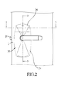
- FIG. 2 is a side view of the embodiment
- FIG. 3 is a sectional view taken along line 3 - 3 in FIG. 2 ;
- FIG. 4 is a partly exploded perspective view of the embodiment
- FIG. 5 is a fragmentary sectional view taken along line 5 - 5 in FIG. 2 ;
- FIG. 6 is a working diagram of an electric control device of the embodiment.
- FIG. 7 is a fragmentary and partly exploded perspective view of the embodiment when the electric door lock is in a repairing operation.
- an electric door lock is adapted to be mounted to a door 1 , and is adapted to lock or unlock the door 1 in an electric control manner.
- the door 1 has an inner surface 11 , an outer surface 12 spaced apart from the inner surface 11 , a side surface 13 vertically connected between the inner and outer surfaces 11 , 12 , and a mounting hole 14 extending through the inner and outer surfaces 11 , 12 .
- the electric door lock includes a lock device 2 adapted to be mounted to the door 1 , and an electric control device 4 received in the lock device 2 , and electrically controlling the lock device 2 .
- the lock device 2 includes a latch bolt 21 movable through the side surface 13 of the door 1 , an inner cover seat 20 adapted to be mounted to the inner surface 11 of the door 1 , an outer cover seat 23 adapted to be mounted to the outer surface 12 of the door 1 , and a handle mechanism 22 adapted to be mounted to the door 1 .
- the handle mechanism 22 drives movement of the latch bolt 21 relative to the side surface 13 of the door 1 , and since the structures of the latch bolt 21 and the handle mechanism 22 , and the connecting relationship between the latch bolt 21 and the handle mechanism 22 are well-known in the art, only the details of related parts will be mentioned in the following description.
- the handle mechanism 22 includes an inner handle unit 221 adapted to be disposed at an inner side of the door 1 , an outer handle unit 222 adapted to be disposed at an outer side of the door 1 , a plurality of coupling members 223 coupling the inner handle unit 221 and the outer handle unit 222 together, and a driving unit 224 adapted to be mounted in the mounting hole 14 of the door 1 , and controlling the movement of the latch bolt 21 .
- the inner handle unit 221 includes an inner fixed seat 225 adapted to be mounted to the inner surface 11 of the door 1 , and an inner handle 226 rotatably mounted to the inner fixed seat 225 .
- the inner fixed seat 225 has a first connecting plate 227 protruding inwardly, and two second connecting plates 228 disposed below the first connecting plate 227 , and protruding inwardly.
- the outer handle unit 222 has an outer fixed seat 229 and an outer handle 220 .
- the coupling members 223 are adapted to fix the inner fixed seat 225 and the outer fixed seat 229 to the door 1 .
- the inner cover seat 20 has an inner cover 24 , a cover body 26 , at least one snap fit mechanism 27 interconnecting the cover body 26 and the inner cover 24 , and a battery box 28 removably mounted to the inner cover 24 . It should be noted that, in this embodiment, the inner cover seat 20 has two snap fit mechanisms 27 , and the number of the snap fit mechanism 27 may be varied in other embodiments.
- the inner cover 24 is adapted to be mounted to the door 1 , and has a cover wall 241 , a surrounding wall 242 extending from the cover wall 241 toward the inner surface 11 of the door 1 , an inner receiving room 243 , and an abutment wall 244 protruding from the cover wall 241 and overlapping the second connecting plates 228 of the handle mechanism 22 .
- the cover wall 241 cooperates with the surrounding wall 242 to define the inner receiving room 243 .
- the cover wall 241 has a handle mounting hole 245 , a window 246 communicated with the inner receiving room 243 , and a button hole 247 formed therethrough and formed between the handle mounting hole 245 and the window 246 .
- the cover wall 241 has a top end defining a bottom end of the window 246 .
- the inner handle 226 of the handle mechanism 22 extends through the handle mounting hole 245 of the inner cover 24 .
- the surrounding wall 242 has two opposite first jointing sections 248 respectively disposed at two opposite sides of the window 246 , a battery opening 249 communicated with a bottom end of the inner receiving room 243 , and a first connecting block 240 disposed proximate to the battery opening 249 .
- the inner cover seat 20 further has a plurality of fixing screws 29 disposed for fixing the inner cover 24 to the inner fixed seat 225 .
- One part of the fixing screws 29 fix the surrounding wall 242 to the first connecting plate 227 , and the remaining part of the fixing screws 29 fix the abutment wall 244 to the second connecting plates 228 .
- the cover body 26 removably covers the window 246 of the inner cover 24 , and has two opposite second jointing sections 261 respectively jointed to the first jointing sections 248 .
- Each of the snap fit mechanisms 27 has a first hook 271 , and a second hook 272 hooked with the first hook 271 .
- the first hooks 271 of the snap fit mechanisms 27 are respectively disposed at the first jointing sections 248 of the inner cover 24
- the second hooks 272 of the snap fit mechanisms 27 are respectively disposed at the second jointing sections 261 of the cap body 26 .
- the configuration of the snap fit mechanism 27 may be varied in other embodiments, for example, a hook may be disposed to engage a groove.
- the battery box 28 is received in the inner receiving room 243 of the inner cover 24 , is removable from the inner receiving room 243 through the battery opening 249 , and has a second connecting block 281 corresponding to the first connecting block 240 in position, and a coupling screw 282 fixing the second connecting block 281 to the first connecting block 240 .
- the outer cover seat 23 has an outer receiving room 230 .
- the electric control device 4 electrically controls the lock device 2 to allow the handle mechanism 22 to drive the movement of the latch bolt 21 .
- the control manner of the electric control device 4 may be varied in different embodiments, for example, image recognition, magnetic card induction, remote control, password control and biological feature identification.
- the magnetic card induction may include RF reception and wireless transmission.
- the remote control may be Bluetooth transmission.
- the biological feature identification may include fingerprint identification and iris identification.
- the electric control device 4 includes a middle circuit board 42 fixedly received in the inner receiving room 243 , and disposed at an outer side of the cover wall 241 of the cover body 24 , an inner circuit board 43 removably received in the inner receiving room 243 , removably connected to the middle circuit board 42 , corresponding to the window 246 in position, and removable from the inner receiving room 243 through the window 246 , at least one power connecting member 40 fixedly mounted to the outer circuit board 43 , and electrically connecting the outer circuit board 43 to the middle circuit board 42 , an outer circuit board 44 received in the outer receiving room 230 , and electrically connected to the middle circuit board 42 , a power source 45 electrically connected to the middle circuit board 42 , a plurality of power supplies 46 received in the battery box 28 , electrically connected to the middle circuit board 42 , and providing electric energy for the power source 45 , and a button 47 mounted to and electrically connected to the middle circuit board 42 , and corresponding to the button hole 247 in position.
- the button 47 is disposed for circuit test and circuit reset.
- the power connecting member 40 is configured as a socket so as to connect the inner circuit board 43 to the middle circuit board 42 , and the configuration of the power connecting member 40 may be varied in other embodiments.
- the middle circuit board 42 drives the power source 45 to allow the handle mechanism 22 to drive the movement of the latch bolt 21 . Since the details of electric control for driving the movement of the latch bolt 21 are well-known in the art, are thus omitted herein for the sake of brevity.
- the inner cover seat 20 further has a plurality of connecting screws 25 fixing the middle circuit board 42 to the inner fixed seat 225 .
- the middle circuit board 42 , the inner circuit board 43 and the outer circuit board 44 can be provided with different electronic members and circuits based on the requirements.
- the disposition of the outer circuit board 44 is based on the control manner requirements, for example, when the electric door lock is driven by a magnetic card, the outer circuit board 44 is provided with the electronic members that can be induced by the magnetic card, and when the electric door lock is driven by a biological feature, the outer circuit board 44 is provided with the electronic members that can identify the biological feature.
- the middle circuit board 42 is preferably provided with the electronic members that is stable and that is not easy to breakdown.
- the middle circuit board 42 is provided with a driving circuit that is connected to the power source 45 and the power supplies 46 , and a connecting circuit that is connected between the inner circuit board 43 and the outer circuit board 44 .
- the inner circuit board 43 is suitable for being provided with the electronic members that may be easy to breakdown, that may be required to be updated, or that may be required to be frequently replaced.
- the power supplies 46 are configured as batteries, and the configuration of the power supplies 46 may be varied in other embodiments such as an indoor power source supply.
- the control manner of the electric door lock is variable, magnetic card induction will be the only one example in the following description.
- the induced signal is firstly transmitted to the inner circuit board 43 through the middle circuit board 42 , and the induced signal is then transmitted back to the outer circuit board 44 through the middle circuit board 42 to drive the outer circuit board 44 to read the data of the magnetic card.
- the read data is then transmitted to the inner circuit board 43 through the middle circuit board 42 to be analyzed.
- the middle circuit board 42 subsequently controls the power source 45 to output a mechanical power to unlock the door 1 , the user can then operate the handle mechanism 22 to drive the movement of the latch bolt 21 .
- the power source 45 will not be driven.
- the control manner is Bluetooth transmission, the inner circuit board 43 will directly drive the middle circuit board 42 to control the power source 45 after receiving the induced signal.
- the user when the power supplies 46 run out of power, the user only requires to remove the coupling screw 282 to remove the battery box 28 from the inner cover 24 , so that the inner handle 226 is also not required to be removed during a battery replacement operation, and such operation is also convenient for the user. Furthermore, since the fixing screws 29 fix the inner cover 24 to the handle mechanism 22 , it is convenient to remove the inner cover 24 from the handle mechanism 22 .
Abstract
Description
Claims (9)
Applications Claiming Priority (3)
| Application Number | Priority Date | Filing Date | Title |
|---|---|---|---|
| TW106207022U TWM547020U (en) | 2017-05-17 | 2017-05-17 | Electronic lock |
| TW106207022 | 2017-05-17 | ||
| TW106207022U | 2017-05-17 |
Publications (2)
| Publication Number | Publication Date |
|---|---|
| US20180334831A1 US20180334831A1 (en) | 2018-11-22 |
| US10145144B1 true US10145144B1 (en) | 2018-12-04 |
Family
ID=60188728
Family Applications (1)
| Application Number | Title | Priority Date | Filing Date |
|---|---|---|---|
| US15/792,554 Active US10145144B1 (en) | 2017-05-17 | 2017-10-24 | Electric door lock |
Country Status (4)
| Country | Link |
|---|---|
| US (1) | US10145144B1 (en) |
| CN (1) | CN207073335U (en) |
| CA (1) | CA2983326C (en) |
| TW (1) | TWM547020U (en) |
Cited By (5)
| Publication number | Priority date | Publication date | Assignee | Title |
|---|---|---|---|---|
| USD883068S1 (en) * | 2018-10-31 | 2020-05-05 | Shenzhen Cnest Electronic Technology Co., Ltd. | Door lock |
| US10704294B1 (en) * | 2017-04-17 | 2020-07-07 | Lockheed Martin Corporation | Wirelessly actuated cover for a structure |
| USD895396S1 (en) * | 2018-05-25 | 2020-09-08 | Sargent Manufacturing Company | Mortise lock translatable status indicator |
| USD896059S1 (en) * | 2018-04-30 | 2020-09-15 | Sargent Manufacturing Company | Mortise lock status indicator |
| USD906086S1 (en) * | 2018-05-23 | 2020-12-29 | Zkteco Co., Ltd. | Smart lock |
Families Citing this family (3)
| Publication number | Priority date | Publication date | Assignee | Title |
|---|---|---|---|---|
| USD889245S1 (en) * | 2018-07-20 | 2020-07-07 | Carrier Corporation | Locking device |
| CN110165103B (en) * | 2019-04-08 | 2021-11-05 | 河南平高电气股份有限公司 | Energy storage device |
| CN112825604B (en) * | 2019-11-20 | 2023-01-06 | 恩坦华产品有限公司 | Modular electronic control unit for vehicle latch and vehicle latch with modular electronic control unit |
Citations (8)
| Publication number | Priority date | Publication date | Assignee | Title |
|---|---|---|---|---|
| US5027629A (en) * | 1990-01-22 | 1991-07-02 | Liu Yin Chic | Control mechanism of electronic lock |
| US20070169526A1 (en) * | 2003-11-20 | 2007-07-26 | Van Der Weide Willibrordus A | Biological fertilizer |
| US20150240530A1 (en) * | 2014-02-25 | 2015-08-27 | Schlage Lock Company Llc | Simplified lever handing apparatus |
| US20160145904A1 (en) * | 2010-02-25 | 2016-05-26 | Sargent Manufacturing Company | Locking device with configurable electrical connector key and internal circuit board for electronic door locks |
| US9822553B1 (en) * | 2016-11-23 | 2017-11-21 | Gate Labs Inc. | Door tracking system and method |
| US20180058103A1 (en) * | 2016-08-26 | 2018-03-01 | Computerized Security Systems, Inc. | Locking system for a door |
| US20180155960A1 (en) * | 2015-06-05 | 2018-06-07 | Sargent & Greenleaf, Inc. | High security electromechanical lock |
| US20180171666A1 (en) * | 2016-12-19 | 2018-06-21 | I-Tek Metal Mfg. Co., Ltd | Modularized Electric Door Lock |
-
2017
- 2017-05-17 TW TW106207022U patent/TWM547020U/en unknown
- 2017-08-02 CN CN201720955841.7U patent/CN207073335U/en not_active Expired - Fee Related
- 2017-10-23 CA CA2983326A patent/CA2983326C/en active Active
- 2017-10-24 US US15/792,554 patent/US10145144B1/en active Active
Patent Citations (8)
| Publication number | Priority date | Publication date | Assignee | Title |
|---|---|---|---|---|
| US5027629A (en) * | 1990-01-22 | 1991-07-02 | Liu Yin Chic | Control mechanism of electronic lock |
| US20070169526A1 (en) * | 2003-11-20 | 2007-07-26 | Van Der Weide Willibrordus A | Biological fertilizer |
| US20160145904A1 (en) * | 2010-02-25 | 2016-05-26 | Sargent Manufacturing Company | Locking device with configurable electrical connector key and internal circuit board for electronic door locks |
| US20150240530A1 (en) * | 2014-02-25 | 2015-08-27 | Schlage Lock Company Llc | Simplified lever handing apparatus |
| US20180155960A1 (en) * | 2015-06-05 | 2018-06-07 | Sargent & Greenleaf, Inc. | High security electromechanical lock |
| US20180058103A1 (en) * | 2016-08-26 | 2018-03-01 | Computerized Security Systems, Inc. | Locking system for a door |
| US9822553B1 (en) * | 2016-11-23 | 2017-11-21 | Gate Labs Inc. | Door tracking system and method |
| US20180171666A1 (en) * | 2016-12-19 | 2018-06-21 | I-Tek Metal Mfg. Co., Ltd | Modularized Electric Door Lock |
Cited By (6)
| Publication number | Priority date | Publication date | Assignee | Title |
|---|---|---|---|---|
| US10704294B1 (en) * | 2017-04-17 | 2020-07-07 | Lockheed Martin Corporation | Wirelessly actuated cover for a structure |
| US10900258B1 (en) | 2017-04-17 | 2021-01-26 | Lockheed Martin Corporation | Wirelessly actuated cover for a structure |
| USD896059S1 (en) * | 2018-04-30 | 2020-09-15 | Sargent Manufacturing Company | Mortise lock status indicator |
| USD906086S1 (en) * | 2018-05-23 | 2020-12-29 | Zkteco Co., Ltd. | Smart lock |
| USD895396S1 (en) * | 2018-05-25 | 2020-09-08 | Sargent Manufacturing Company | Mortise lock translatable status indicator |
| USD883068S1 (en) * | 2018-10-31 | 2020-05-05 | Shenzhen Cnest Electronic Technology Co., Ltd. | Door lock |
Also Published As
| Publication number | Publication date |
|---|---|
| CA2983326C (en) | 2020-08-25 |
| US20180334831A1 (en) | 2018-11-22 |
| CN207073335U (en) | 2018-03-06 |
| TWM547020U (en) | 2017-08-11 |
| CA2983326A1 (en) | 2018-11-17 |
Similar Documents
| Publication | Publication Date | Title |
|---|---|---|
| US10145144B1 (en) | Electric door lock | |
| US10208508B2 (en) | Modularized electric door lock | |
| CA2729544C (en) | Electronic door lock with modular components | |
| AU2012225189B2 (en) | A lock assembly | |
| US20050132766A1 (en) | Lock assembly | |
| US20180058103A1 (en) | Locking system for a door | |
| CN206319716U (en) | Modular electrical minor door lock | |
| CN108915402A (en) | A kind of Fingerprint Lock of double verification | |
| CN208122510U (en) | A kind of fixed device of the smart machine of Europe superscript door lock | |
| CN210598510U (en) | Intelligent electronic drawer lock | |
| KR101513928B1 (en) | Module for Locking Door in Electrical Operation and System Having The Same | |
| CN210714118U (en) | Fingerprint identification handle and door lock system | |
| CN208122511U (en) | A kind of fixed device of the smart machine of knob locks | |
| KR101043933B1 (en) | Door Locking Device | |
| CN209687015U (en) | The unlocking apparatus of mechanical lock | |
| KR101071685B1 (en) | Digital door lock easy to install | |
| CN219352071U (en) | LED display screen | |
| KR100514116B1 (en) | Locking device for electric type door-lock | |
| CN207673142U (en) | Fingerprint lock controller | |
| CN217269449U (en) | A adjust structure, lock subassembly for lock | |
| CN210519220U (en) | Electronic component plug-in positioning device | |
| US11761243B2 (en) | Clutch mechanism and electronic lock having the same | |
| CN210563789U (en) | Intelligent handrail | |
| CN209942410U (en) | Anti-theft structure of intelligence lock | |
| KR101339374B1 (en) | Lock box of the Door locking device and manufacturing method the same |
Legal Events
| Date | Code | Title | Description |
|---|---|---|---|
| AS | Assignment |
Owner name: TUNG LUNG HARDWARE MANUFACTURING CO., LTD., TAIWAN Free format text: ASSIGNMENT OF ASSIGNORS INTEREST;ASSIGNORS:SHYU, SONG-GEN;CHEN, PO-YANG;CHANG, CHIA-CHEN;AND OTHERS;REEL/FRAME:043940/0178 Effective date: 20171010 |
|
| FEPP | Fee payment procedure |
Free format text: ENTITY STATUS SET TO UNDISCOUNTED (ORIGINAL EVENT CODE: BIG.); ENTITY STATUS OF PATENT OWNER: SMALL ENTITY Free format text: ENTITY STATUS SET TO UNDISCOUNTED (ORIGINAL EVENT CODE: BIG.); ENTITY STATUS OF PATENT OWNER: LARGE ENTITY |
|
| STCF | Information on status: patent grant |
Free format text: PATENTED CASE |
|
| AS | Assignment |
Owner name: TLHM CO., LTD., TAIWAN Free format text: CHANGE OF NAME;ASSIGNOR:TUNG LUNG HARDWARE MANUFACTURING CO., LTD.;REEL/FRAME:053222/0909 Effective date: 20200616 |
|
| FEPP | Fee payment procedure |
Free format text: ENTITY STATUS SET TO SMALL (ORIGINAL EVENT CODE: SMAL); ENTITY STATUS OF PATENT OWNER: SMALL ENTITY |
|
| MAFP | Maintenance fee payment |
Free format text: PAYMENT OF MAINTENANCE FEE, 4TH YR, SMALL ENTITY (ORIGINAL EVENT CODE: M2551); ENTITY STATUS OF PATENT OWNER: SMALL ENTITY Year of fee payment: 4 |