US10134097B2 - Controlling the distribution of energy resources on a smart grid - Google Patents
Controlling the distribution of energy resources on a smart grid Download PDFInfo
- Publication number
- US10134097B2 US10134097B2 US14/759,090 US201414759090A US10134097B2 US 10134097 B2 US10134097 B2 US 10134097B2 US 201414759090 A US201414759090 A US 201414759090A US 10134097 B2 US10134097 B2 US 10134097B2
- Authority
- US
- United States
- Prior art keywords
- devices
- resources
- resource
- shiftable
- controllable
- Prior art date
- Legal status (The legal status is an assumption and is not a legal conclusion. Google has not performed a legal analysis and makes no representation as to the accuracy of the status listed.)
- Active, expires
Links
Images


Classifications
-
- G—PHYSICS
- G06—COMPUTING; CALCULATING OR COUNTING
- G06Q—INFORMATION AND COMMUNICATION TECHNOLOGY [ICT] SPECIALLY ADAPTED FOR ADMINISTRATIVE, COMMERCIAL, FINANCIAL, MANAGERIAL OR SUPERVISORY PURPOSES; SYSTEMS OR METHODS SPECIALLY ADAPTED FOR ADMINISTRATIVE, COMMERCIAL, FINANCIAL, MANAGERIAL OR SUPERVISORY PURPOSES, NOT OTHERWISE PROVIDED FOR
- G06Q50/00—Systems or methods specially adapted for specific business sectors, e.g. utilities or tourism
- G06Q50/06—Electricity, gas or water supply
-
- G—PHYSICS
- G06—COMPUTING; CALCULATING OR COUNTING
- G06Q—INFORMATION AND COMMUNICATION TECHNOLOGY [ICT] SPECIALLY ADAPTED FOR ADMINISTRATIVE, COMMERCIAL, FINANCIAL, MANAGERIAL OR SUPERVISORY PURPOSES; SYSTEMS OR METHODS SPECIALLY ADAPTED FOR ADMINISTRATIVE, COMMERCIAL, FINANCIAL, MANAGERIAL OR SUPERVISORY PURPOSES, NOT OTHERWISE PROVIDED FOR
- G06Q10/00—Administration; Management
- G06Q10/04—Forecasting or optimisation specially adapted for administrative or management purposes, e.g. linear programming or "cutting stock problem"
-
- G—PHYSICS
- G06—COMPUTING; CALCULATING OR COUNTING
- G06Q—INFORMATION AND COMMUNICATION TECHNOLOGY [ICT] SPECIALLY ADAPTED FOR ADMINISTRATIVE, COMMERCIAL, FINANCIAL, MANAGERIAL OR SUPERVISORY PURPOSES; SYSTEMS OR METHODS SPECIALLY ADAPTED FOR ADMINISTRATIVE, COMMERCIAL, FINANCIAL, MANAGERIAL OR SUPERVISORY PURPOSES, NOT OTHERWISE PROVIDED FOR
- G06Q30/00—Commerce
- G06Q30/02—Marketing; Price estimation or determination; Fundraising
- G06Q30/0201—Market modelling; Market analysis; Collecting market data
- G06Q30/0206—Price or cost determination based on market factors
-
- G—PHYSICS
- G06—COMPUTING; CALCULATING OR COUNTING
- G06Q—INFORMATION AND COMMUNICATION TECHNOLOGY [ICT] SPECIALLY ADAPTED FOR ADMINISTRATIVE, COMMERCIAL, FINANCIAL, MANAGERIAL OR SUPERVISORY PURPOSES; SYSTEMS OR METHODS SPECIALLY ADAPTED FOR ADMINISTRATIVE, COMMERCIAL, FINANCIAL, MANAGERIAL OR SUPERVISORY PURPOSES, NOT OTHERWISE PROVIDED FOR
- G06Q50/00—Systems or methods specially adapted for specific business sectors, e.g. utilities or tourism
- G06Q50/10—Services
-
- H—ELECTRICITY
- H02—GENERATION; CONVERSION OR DISTRIBUTION OF ELECTRIC POWER
- H02J—CIRCUIT ARRANGEMENTS OR SYSTEMS FOR SUPPLYING OR DISTRIBUTING ELECTRIC POWER; SYSTEMS FOR STORING ELECTRIC ENERGY
- H02J3/00—Circuit arrangements for ac mains or ac distribution networks
- H02J3/12—Circuit arrangements for ac mains or ac distribution networks for adjusting voltage in ac networks by changing a characteristic of the network load
- H02J3/14—Circuit arrangements for ac mains or ac distribution networks for adjusting voltage in ac networks by changing a characteristic of the network load by switching loads on to, or off from, network, e.g. progressively balanced loading
-
- H02J2003/143—
-
- H02J2003/146—
-
- H—ELECTRICITY
- H02—GENERATION; CONVERSION OR DISTRIBUTION OF ELECTRIC POWER
- H02J—CIRCUIT ARRANGEMENTS OR SYSTEMS FOR SUPPLYING OR DISTRIBUTING ELECTRIC POWER; SYSTEMS FOR STORING ELECTRIC ENERGY
- H02J2310/00—The network for supplying or distributing electric power characterised by its spatial reach or by the load
- H02J2310/10—The network having a local or delimited stationary reach
- H02J2310/12—The local stationary network supplying a household or a building
- H02J2310/14—The load or loads being home appliances
-
- H—ELECTRICITY
- H02—GENERATION; CONVERSION OR DISTRIBUTION OF ELECTRIC POWER
- H02J—CIRCUIT ARRANGEMENTS OR SYSTEMS FOR SUPPLYING OR DISTRIBUTING ELECTRIC POWER; SYSTEMS FOR STORING ELECTRIC ENERGY
- H02J2310/00—The network for supplying or distributing electric power characterised by its spatial reach or by the load
- H02J2310/50—The network for supplying or distributing electric power characterised by its spatial reach or by the load for selectively controlling the operation of the loads
- H02J2310/56—The network for supplying or distributing electric power characterised by its spatial reach or by the load for selectively controlling the operation of the loads characterised by the condition upon which the selective controlling is based
- H02J2310/62—The condition being non-electrical, e.g. temperature
- H02J2310/64—The condition being economic, e.g. tariff based load management
-
- Y—GENERAL TAGGING OF NEW TECHNOLOGICAL DEVELOPMENTS; GENERAL TAGGING OF CROSS-SECTIONAL TECHNOLOGIES SPANNING OVER SEVERAL SECTIONS OF THE IPC; TECHNICAL SUBJECTS COVERED BY FORMER USPC CROSS-REFERENCE ART COLLECTIONS [XRACs] AND DIGESTS
- Y02—TECHNOLOGIES OR APPLICATIONS FOR MITIGATION OR ADAPTATION AGAINST CLIMATE CHANGE
- Y02B—CLIMATE CHANGE MITIGATION TECHNOLOGIES RELATED TO BUILDINGS, e.g. HOUSING, HOUSE APPLIANCES OR RELATED END-USER APPLICATIONS
- Y02B70/00—Technologies for an efficient end-user side electric power management and consumption
- Y02B70/30—Systems integrating technologies related to power network operation and communication or information technologies for improving the carbon footprint of the management of residential or tertiary loads, i.e. smart grids as climate change mitigation technology in the buildings sector, including also the last stages of power distribution and the control, monitoring or operating management systems at local level
- Y02B70/3225—Demand response systems, e.g. load shedding, peak shaving
-
- Y02B70/3266—
-
- Y—GENERAL TAGGING OF NEW TECHNOLOGICAL DEVELOPMENTS; GENERAL TAGGING OF CROSS-SECTIONAL TECHNOLOGIES SPANNING OVER SEVERAL SECTIONS OF THE IPC; TECHNICAL SUBJECTS COVERED BY FORMER USPC CROSS-REFERENCE ART COLLECTIONS [XRACs] AND DIGESTS
- Y04—INFORMATION OR COMMUNICATION TECHNOLOGIES HAVING AN IMPACT ON OTHER TECHNOLOGY AREAS
- Y04S—SYSTEMS INTEGRATING TECHNOLOGIES RELATED TO POWER NETWORK OPERATION, COMMUNICATION OR INFORMATION TECHNOLOGIES FOR IMPROVING THE ELECTRICAL POWER GENERATION, TRANSMISSION, DISTRIBUTION, MANAGEMENT OR USAGE, i.e. SMART GRIDS
- Y04S20/00—Management or operation of end-user stationary applications or the last stages of power distribution; Controlling, monitoring or operating thereof
- Y04S20/20—End-user application control systems
- Y04S20/222—Demand response systems, e.g. load shedding, peak shaving
-
- Y04S20/224—
-
- Y—GENERAL TAGGING OF NEW TECHNOLOGICAL DEVELOPMENTS; GENERAL TAGGING OF CROSS-SECTIONAL TECHNOLOGIES SPANNING OVER SEVERAL SECTIONS OF THE IPC; TECHNICAL SUBJECTS COVERED BY FORMER USPC CROSS-REFERENCE ART COLLECTIONS [XRACs] AND DIGESTS
- Y04—INFORMATION OR COMMUNICATION TECHNOLOGIES HAVING AN IMPACT ON OTHER TECHNOLOGY AREAS
- Y04S—SYSTEMS INTEGRATING TECHNOLOGIES RELATED TO POWER NETWORK OPERATION, COMMUNICATION OR INFORMATION TECHNOLOGIES FOR IMPROVING THE ELECTRICAL POWER GENERATION, TRANSMISSION, DISTRIBUTION, MANAGEMENT OR USAGE, i.e. SMART GRIDS
- Y04S20/00—Management or operation of end-user stationary applications or the last stages of power distribution; Controlling, monitoring or operating thereof
- Y04S20/20—End-user application control systems
- Y04S20/242—Home appliances
-
- Y—GENERAL TAGGING OF NEW TECHNOLOGICAL DEVELOPMENTS; GENERAL TAGGING OF CROSS-SECTIONAL TECHNOLOGIES SPANNING OVER SEVERAL SECTIONS OF THE IPC; TECHNICAL SUBJECTS COVERED BY FORMER USPC CROSS-REFERENCE ART COLLECTIONS [XRACs] AND DIGESTS
- Y04—INFORMATION OR COMMUNICATION TECHNOLOGIES HAVING AN IMPACT ON OTHER TECHNOLOGY AREAS
- Y04S—SYSTEMS INTEGRATING TECHNOLOGIES RELATED TO POWER NETWORK OPERATION, COMMUNICATION OR INFORMATION TECHNOLOGIES FOR IMPROVING THE ELECTRICAL POWER GENERATION, TRANSMISSION, DISTRIBUTION, MANAGEMENT OR USAGE, i.e. SMART GRIDS
- Y04S50/00—Market activities related to the operation of systems integrating technologies related to power network operation or related to communication or information technologies
- Y04S50/10—Energy trading, including energy flowing from end-user application to grid
-
- Y—GENERAL TAGGING OF NEW TECHNOLOGICAL DEVELOPMENTS; GENERAL TAGGING OF CROSS-SECTIONAL TECHNOLOGIES SPANNING OVER SEVERAL SECTIONS OF THE IPC; TECHNICAL SUBJECTS COVERED BY FORMER USPC CROSS-REFERENCE ART COLLECTIONS [XRACs] AND DIGESTS
- Y04—INFORMATION OR COMMUNICATION TECHNOLOGIES HAVING AN IMPACT ON OTHER TECHNOLOGY AREAS
- Y04S—SYSTEMS INTEGRATING TECHNOLOGIES RELATED TO POWER NETWORK OPERATION, COMMUNICATION OR INFORMATION TECHNOLOGIES FOR IMPROVING THE ELECTRICAL POWER GENERATION, TRANSMISSION, DISTRIBUTION, MANAGEMENT OR USAGE, i.e. SMART GRIDS
- Y04S50/00—Market activities related to the operation of systems integrating technologies related to power network operation or related to communication or information technologies
- Y04S50/14—Marketing, i.e. market research and analysis, surveying, promotions, advertising, buyer profiling, customer management or rewards
Definitions
- the present invention relates to a smart grid system and a method for distributing resources in the smart grid system.
- a smart grid system is aimed at decreasing power consumption. Technologies turning devices on or off are generally disclosed for the reduction of power consumption, as described in Korean publication No. 2012-0097551.
- the prior smart grid system does not provide an appropriate method for distributing energy in order to use energy efficiently.
- an aspect of the present invention is to maximize the resource usage efficiency with reducing the cost.
- a smart grid system comprises at least one non-shiftable device; at least one controllable device; and at least one shiftable device; wherein price data are provided at each stage, the non-shiftable device is always provided with its resource requirements, the controllable device is provide with resources in the range of its resource requirements, and the shiftable device has its resource requirements but not allowed to be provided with resources at the stage when resource price is highest.
- a resource distribution method of smart grid system comprises determining available resources based on price data; and distributing the available resources differently to at least one device of a plurality of devices; wherein considering priority, fairness, and cost, given weighting factors, respectively, in the distribution of the available resources, and the weighting factors being more than zero.
- a resource distribution method of smart grid system comprises determining reserved resources for each device based on historical data including resource information used during previous stages; comparing the determined reserved resources with resources required by the each device; and classifying the devices based on the comparison results; wherein the devices are classified into S-device with surplus resources if the determined reserved resources are more than the required resources, while the devices are classified into D-device with deficiency resources if the determined reserved resources are less than the required resources.
- a resource distribution method of smart grid system comprises determining available resources based on price data at stage; selecting an optimal strategy among the pre-specified strategies; and distributing the determined available resources to devices according to the selected strategy; wherein the price data are provided from stage to stage, the selected strategy has the highest satisfaction level of resource usage of the devices at the stage.
- the present invention can optimize the efficiency of resource usage since the system and method of the present invention distribute the resource (energy) from the utility to the devices appropriately according to the characteristics of devices, and provide the surplus resources to the deficiency devices.
- the present invention can reduce the cost of resource consumption since the system of the invention do not provide the resource to the shiftable devices at the stage when the price is high, and provides the resource to the shiftable devices at the stage when the price is low.
- the present invention can reduce the load of utility and avoid a blackout accordingly since the resource consumption decreases at the time when a great deal of energy is consumed in an aspect of the utility company.
- FIG. 1 is a diagram of a smart grid system according to the present invention.
- FIG. 2 is a flowchart of resource distribution process in a smart grid system according to the first embodiment of the present invention.
- FIG. 3 is a flowchart of resource distribution process in a smart grid system according to the second embodiment of the present invention.
- FIG. 4 is a flowchart of resource distribution process in a smart grid system according to the third embodiment of the present invention.
- FIGS. 5 and 6 are flowcharts of resource distribution process in a smart grid system according to the fourth embodiment of the present invention.
- FIG. 7 is a block diagram of a resource usage management unit according to the present invention.
- FIG. 8 is a block diagram of an interface according to the present invention.
- FIG. 9 depicts a graph of hourly price data according to the present invention.
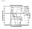
- FIGS. 10 to 14 depict the simulation results using various strategies according to the present invention.
- FIG. 15 depicts the simulation results using an optimal strategy for each stage according to the present invention.
- FIG. 16 depicts the cost comparison results according to the present invention.
- the invention discloses a smart grid system for reducing the cost to maximize energy efficiency.
- the smart grid system presents the method which minimizes the cost to maximize power (resource) usage efficiency in the smart grid environments.
- the resource price may be changed at each of the predetermined unit time (e.g., 30 minutes or hourly). Accordingly, it is important to reduce the cost to maximize resource usage efficiency by reducing the resource consumption when the resource price is high while increasing the resource consumption when the resource price is low.
- the smart grid system of the invention can distribute the resource appropriately considering the smart grid environments (e.g., characteristics of building and individual devices).
- the invention presents a system in which surplus devices (S-devices) bargain with deficiency devices (D-devices), wherein S-devices are the devices having their requirement less than the reserved resources and D-devices having their requirement more than the reserved resources. Accordingly, the invention is able to maximize the utility of resource without a waste of resource though the same resources are provided to the buildings and so on.
- S-devices surplus devices
- D-devices deficiency devices
- the smart grid system of the invention establishes the strategies at each stage.
- the invention establishes a plurality of strategies in advance and uses a method to choose an appropriate strategy among the plurality of strategies pre-specified to maximize the utility efficiency.
- the chosen strategy may be an optimal strategy to maximize the resource usage satisfaction of the devices at the corresponding stage.
- the system can reduce the user's payments with maximizing the resource efficiency and improve the operation efficiency of the devices because it can provide their required resources to the devices to which the resource consumption is essential.
- the present invention divides the devices (the loads) into three classes.
- the devices include non-shiftable devices, controllable devices and shiftable devices.
- Non-shiftable devices must consume an uninterrupted resource regardless of the resource cost.
- Controllable devices require a resource consumption but can adjust their amount of resource to be consumed.
- Shiftable devices can schedule their operation during off-peak hours avoiding expensive on-peak hours. Examples of non-shiftable devices include office PCs, alarm system and refrigerators in homes.
- Controllable devices include dimming lighting and HVAC units.
- Non-shiftable device include dishwashers and plug-in hybrid electric vehicles.
- the devices may be divided into different classes, and it will be understood by those skilled in the art that various changes in class may be made therein without departing from the spirit and scope of the invention.
- non-shiftable devices have first priority
- controllable device have second priority
- shiftable devices have third priority
- Non-shiftable devices have the highest priority in resource distribution.
- FIG. 1 illustrates a smart grid system according to the present invention.
- the smart grid system includes a utility side for providing a resource (energy) and a consumer side for consuming a resource and paying.
- the utility provides an interface ( 100 ) of the consumer side with the unit price data.
- the consumer sends the consumption data to the utility via the interface ( 100 ).
- the consumption data include resource consumption data from the individual devices in the consumer side.
- the interface ( 100 ) manages a resource consumption of the individual devices in building based on the unit price data from the utility, and provides the consumption data to the utility.
- the interface ( 100 ) may be ESI (Energy Service Interface) located in the consumer side.
- the consumption data may be collected from each device by mirroring at each stage, and are transferred to the utility via the interface ( 100 ). Therefore, the utility can identify the current resource amount of consumers based on the consumption data.
- the consumption data are transferred to a resource usage manager ( 102 ) to estimate the future usage amount of resources.
- the resource usage manager ( 102 ) (not shown in the FIG. 1 ) is located at the consumer side to be connected to the interface ( 100 ), and can totally control the operations such as resource distribution, bargaining, strategy planning and so on based on the price data, consumption data, historical data, etc. for the efficiency of resource usage.
- the resource usage manager ( 102 ) may be ESR (Energy System Regulator).
- the historical data are calculated from the consumption data on a daily and hourly basis, which have the information for the resource usage of each device.
- the historical data are stored at the resource usage manager ( 102 ) or may be stored at the separate EMS (Energy Management System).
- the resource usage manager ( 102 ) manages the data or information such as the unit price data, consumption data, the historical data, priority data, available budget, device information and strategies.
- the available budget is specified monthly, daily or hourly in light of the needs of each customer, who can consume its resources in the range of the specified available budget.
- the resource usage manager ( 102 ) classifies the devices into non-shiftable devices, controllable devices and shiftable devices.
- the resource amount of non-shiftable devices may be a fixed value, that of controllable devices may vary in the predetermined range, and that of shiftable device is specified nominally but may not be guaranteed.
- Controllable devices have maximum and minimum values of resource requirements, wherein the minimum value is guaranteed.
- the resource usage manager ( 102 ) assigns the priority to each device. For example, higher priority is always given to non-shiftable devices, followed by controllable devices and shiftable devices.
- the resources are distributed to the devices based on the priority of devices which depends upon their characteristics and importance, as well as the stage in which they are operated. The priority of the same device is determined differently for each consumer or at each stage. Also, the consumers can change the priority at random.
- the resource usage manager ( 102 ) calculates the available resources to be distributed to the devices based on the unit price data received from the utility, allocates resources to each device temporally, determines S-devices and D-devices based on the history of resource consumption, and redistributes surplus resources of S-devices to D-devices
- the resource usage manager ( 102 ) does not distribute resources to shiftable devices at the peak stage when the resource price is high, and can provide resources to shiftable devices at the stage when the resource price is low; thus the invention can reduce the total cost by decreasing resource consumption at the peak stage.
- the invention can reduce the load of utility by decreasing resource consumption as described earlier.
- the resource usage manager ( 102 ) includes predetermined strategies, and can choose one of strategies at each stage.
- the strategy chosen by the unit ( 102 ) is a strategy which maximizes the resource consumption satisfaction of device at the corresponding stage.
- the choice of strategies are realized by scoring strategies at each stage.
- the interface ( 100 ) is the ESI and the resource usage manager ( 102 ) is the ESR.
- FIG. 2 is a flowchart of resource distribution process in the smart grid system according to the first embodiment of the present invention.
- the ESR ( 102 ) classifies the devices in buildings into the three classes, i.e., non-shiftable devices, controllable devices and shiftable devices (Step 200 ). These classes may be categorized considering the characteristics of devices and buildings.
- the ESR ( 102 ) calculates available resources based on the price data received from the utility (Step 202 ). That is, the ESR ( 102 ) calculates resources available at the current stage. The available resources are calculated based on the price data and available cost, which will be described in detail later.
- the ESR ( 102 ) performs a control operation to distribute resources to each device (Step 204 ).
- the ESR ( 102 ) is configured to provide all resource requirements to non-shiftable devices, to provide resources to controllable devices in the range of resource requirements, and to provide resource requirements to shiftable devices at the stage when the price is low, while not to provide resource requirements to shiftable devices at the stage when the price is high.
- the ESR ( 102 ) is configured to provide resources to non-shiftable devices with a higher priority when resources are not sufficient, and to provide resources to controllable devices and shiftable devices in order when resources still remain.
- the smart grid system of the invention classifies the devices into the three classes, assigns a priority to the classified devices and distributes resources based on the priority.
- FIG. 3 is a flowchart of resource distribution process in the smart grid system according to the second embodiment of the present invention.
- the ESI ( 100 ) reserves resources for the different devices, using the history data (Step 300 ).
- the ESI ( 100 ) may not distribute as much resources as the reserved to the devices.
- the ESR ( 102 ) calculates resource surplus and deficiency for the different devices (Step 302 ). Concretely, the ESR ( 102 ) calculates difference between resources reserved for the different devices and resources required by the devices. The ESR ( 102 ) determines surplus if the reserved resource amount is more than the required while it determines deficiency if the reserved resource amount is less than the required.
- the ESR ( 102 ) bargains surplus resources (Step 304 ).
- the ESR ( 102 ) performs a control operation to provide surplus resource of the S-devices to the D-devices.
- the ESR ( 102 ) can provide surplus resources to non-shiftable device which is deficient in resources with a higher priority.
- the smart grid system of the invention distributes surplus resource of the S-devices to the D-devices, it can avoid an unnecessary consumption of resources and enables D-devices to operate ordinarily. Thus, it can address the improved usage efficiency without a waste of resource consumption.
- FIG. 4 is a flowchart of resource distribution process in the smart grid system according to the third embodiment of the present invention.
- an algorithm for resource distribution algorithm starts at the 1 st day, i.e., at 00:00 A.M (Step 400 ).
- the ESR ( 102 ) selects an optimal strategy among the pre-specified strategies in stage 1 which is first stage during the 1 st day (Step 402 ).
- the optimal strategy is a strategy which maximizes the efficiency of resource usage in stage 1 , i.e., having the highest satisfaction level of resource usage of devices.
- the ESR ( 102 ) selects a strategy having the highest score after scoring the strategies in the corresponding stage.
- the ESR ( 102 ) calculates the bargaining utility which indicates the level of satisfaction of devices, for each pre-specified strategy, as described later.
- the ESR ( 102 ) selects the bargaining utility having the highest (i.e., the optimal bargaining utility) value comparing the calculated bargaining utility, so that a strategy having the selected bargaining utility results in an optimal strategy in stage 1 .
- the pre-specified strategies may be the same in all stages, or different in some stages. Also, other indicators may be used to select the optimal strategy among the pre-specified strategies, except the bargaining utility.
- the ESR ( 102 ) applies the selected strategy to the devices. That is, the ESR ( 102 ) distributes available resources to the devices based on the selected strategy (Step 404 ).
- stage 1 ends and stage 2 starts, the ESR ( 102 ) selects an optimal strategy among the pre-specified strategies (Step 406 ).
- the ESR ( 102 ) calculates the bargaining utility for each pre-specified strategy, and selects the optimal bargaining utility among the calculated bargaining utilities, so that a strategy having the selected bargaining utility is selected as an optimal strategy in stage 2
- the ESR ( 102 ) applies the selected strategy to the devices. That is, the ESR ( 102 ) distributes available resources to the devices based on the selected strategy (Step 404 ).
- the ESR ( 102 ) iterates the process in the same way as described above to the last stage of the 1 st day. That is, the ESR ( 102 ) iterates the process until it compares the bargaining utility in the last stage of 1 st day to choose an optimal strategy and apply it to the devices (steps 410 and 412 ). For instance, one day consists of twenty-four stages if a stage is an hour. Accordingly, the process to choose an optimal strategy and apply it to the devices is performed from stage 1 to stage 24 during the 1 st day. That is, the ESR ( 102 ) iterates the process for each stage. The stage may be divided on the unit basis other than daily basis.
- steps 400 to 412 are performed again.
- the process to choose an optimal strategy and apply it to the devices is performed iteratively from stage 1 to stage 24 during the next day.
- the process may be performed iteratively daily.
- the smart grid system of the invention pre-specifies the strategies, chooses an optimal strategy among the pre-specified strategies and applies it to the devices at each stage.
- This process to choose an optimal strategy and apply it to the devices is performed iteratively and infinitely for each stage, so that it can address an improved efficiency of strategy.
- FIGS. 5 and 6 are flowcharts of resource distribution process in the smart grid system according to the fourth embodiment of the present invention. For ease of illustration, it is assumed that stage is on an hourly basis.
- the ESR ( 102 ) determines the available resource R j ava and reference resource RR j i for each device at stage j (Step 500 ).
- the ESR ( 102 ) receives the price data from the utility company, determines the cost at stage j, and calculates the available resource R j ava for stage j as follows:
- R j ava Hourly ⁇ ⁇ budget ⁇ ⁇ ( $ ) Hourly ⁇ ⁇ Unit ⁇ ⁇ Rate ⁇ ⁇ ( $ ⁇ / ⁇ kWh ) ( 1 )
- the unit price data varies from stage to stage, since the utility forecasts the unit rates based on consumption data collected during previous stages.
- the available resource R j ava varies from stage to stage according to (1)
- the reference resource RR j i for device i at stage j is used to estimate requirements for each device at each stage.
- historical data are used to calculate reference resources, since the daily requirements for each device do not vary a great deal from one day to the next.
- the ESR ( 102 ) calculates the reference resource RR j i , using linear prediction model.
- the reference resource RR j i is determined from the following model:
- m RR j i denotes the reference resource of device i at stage j, calculated m days ago.
- the model for the reference resource may be calculated separately for weekdays and weekends.
- the ESI ( 100 ) reserves resources for the different devices (Step 502 ).
- the reserved resource ⁇ j i is calculated from the following formula:
- the main reason for including the reference resource in (3) is to reduce the number of transactions during the bargaining process.
- the ESR ( 102 ) calculates resource surplus/deficiency R j i,sd for each device and the total surplus R j ss (Step 504 ).
- the required resource is a fixed value for an non-shiftable device, the minimum required resources for a controllable device, and not specified for a shiftable-device.
- the devices are classified into S-device with surplus resources and D-device with resource deficiency according to (4).
- the resource surplus for each device is calculated according to (4), and then the total resource surplus is calculated, summing the calculated surplus.
- the ESR ( 102 ) determines if the surplus satisfies the non-shiftable devices (Step 506 ).
- the ESR ( 102 ) determines if the surplus satisfies the non-shiftable D-devices.
- the ESR ( 102 ) increases the cost (Step 508 ) and returns to Step 500 because resources for non-shiftable devices are essential.
- the ESR ( 102 ) determines that the amount of resource surplus is sufficient for the non-shiftable D-devices (Step 510 ).
- the ESR ( 102 ) determines if the surplus satisfies the controllable devices (Step 512 ).
- the ESR ( 102 ) determines if the surplus satisfies the minimum requirements of controllable D-devices.
- the ESR ( 102 ) increases the cost (Step 508 ) and returns to Step 500 .
- the ESR ( 102 ) chooses a particular strategy among the pre-specified strategies and applies it to the devices (Step 600 ). If the surplus remains, the ESR ( 102 ) determines if the remained surplus satisfies the maximum requirements of controllable D-devices and the requirements of shiftable devices, and then chooses a strategy.
- the ESR ( 102 ) performs a bargaining process.
- the ESR ( 102 ) determines if the resource surplus remains (Step 602 ).
- the ESR ( 102 ) determines the reserved bargaining resources (Step 610 ).
- the ESR calculates the resource bargaining unit RBU i k (Step 604 ).
- the resource bargaining unit is iteratively distributed to all D-devices. For controllable devices, the size of the resource bargaining unit at k-th iteration of stage j is given by
- RBU_C j k min ⁇ [ min C k ⁇ ⁇ j k , R jk ss C k ] ( 5 )
- R jk ss is the total surplus of the k-th iteration in the bargaining process at stage j
- C k is the number of controllable devices whose resources do not reach their maximum requirements in the k-th iteration
- ⁇ j k is the gap between the current resource allocation and the maximum requirements of a controllable device.
- RBU_S j k min ⁇ [ min S k ⁇ ⁇ j k , R jk ss S k ] ( 6 )
- R jk ss is the total surplus of the k-th iteration in bargaining process at stage j
- S k is the number of shiftable devices whose resources do not reach their nominal requirements at the k-th iteration
- ⁇ j k is the gap between the current resource allocation and the nominal requirements of a shiftable device.
- the ESR ( 102 ) provides the resource bargaining unit (Step 606 ).
- the ESR ( 102 ) determines if the resource surplus satisfies controllable devices (Step 608 ).
- the ESR ( 102 ) returns to step 602 if the resource surplus do not satisfy controllable devices, while ESR ( 102 ) calculates the reserved bargaining resource ⁇ j i (B x ) for each device (Step 610 ).
- the ESR ( 102 ) initiates resource bargaining among the different kinds of devices.
- the resource bargaining unit RBU i k is iteratively distributed to D-devices that need more resources.
- the ESR ( 102 ) subtracts RBU i k from RBU ss jk . This process continues until all devices have been satisfied or the surplus has been exhausted.
- the ESR ( 102 ) calculates the bargaining utility U J (B x ) for each strategy x at stage j (Step 612 ).
- the bargaining utility is a dimensionless quantity that describes the satisfaction level of devices for a given set of strategies.
- the bargaining utility function is also system-dependent, and may be determined by energy management policies of buildings and so on.
- the ESR ( 102 ) determines if new strategies are available or not (Step 614 ).
- the ESR ( 102 ) returns to step 600 if the new strategies are available, while the ESR ( 102 ) calculates the equilibrium utility from all the strategies, and determines the equilibrium strategy based on the calculation results if the new strategies are not available (Step 616 ).
- the ESR ( 102 ) calculates the bargaining solution that maximizes the satisfaction of devices based on the calculation of U J (B x ) using different strategies, and determines the strategy based on the calculated bargaining solution.
- the bargaining solution can be calculated via the following formula:
- the smart grid system of the invention distributes the surplus to the devices at the resource bargaining unit, and determines the strategy that maximizes the satisfaction of devices
- the surplus resources are provided to the D-device with highest priority.
- the surplus resources are firstly provided to the controllable D-devices, and next to the shiftable devices if the surplus resources still remain.
- the smart grid system of the invention provides RBUs (Resource Bargaining Unit) to the controllable D-device with highest priority until its maximum requirement has been satisfied, and then to the controllable D-device with next highest priority until its maximum requirement has been satisfied.
- RBUs Resource Bargaining Unit
- the surplus resources are firstly provided to the controllable D-devices, and next to the shiftable devices if the surplus resources still remain.
- the smart grid system of the invention provides one RBU to the controllable D-device with highest priority, and then to the controllable D-device with next highest priority, instead of satisfying one controllable D-device at a time.
- the surplus resources are provided to controllable D-devices until all controllable D-devices have been satisfied, and then to shiftable D-devices if the surplus resources still remain after all controllable D-devices have been satisfied. This process ceases if the surplus has been exhausted or all shiftable D-devices have been satisfied.
- the smart grid system of the invention provides one RBU to the controllable D-device with highest priority, and then to the controllable D-device with next highest priority. After distributing one RBU to all controllable D-devices, all shiftable devices are provided with one RBU in the same way. After that, if the surplus resources remains, the process returns to the controllable D-devices and repeat itself, continuing until the surplus has been exhausted or all shiftable D-devices have been satisfied
- the smart grid system of the invention provides the surplus resources to devices with smaller gaps between their current resources and maximum/nominal resources.
- the smart grid system of the invention provides RBUs to the controllable D-device with smallest gap until its maximum requirement has been satisfied, and then to the controllable D-device with next smallest gap. After all controllable D-devices have been satisfied, if the surplus resources remain, the process continues to the shiftable D-devices. The process ceases if the surplus has been exhausted or all shiftable D-devices have been satisfied.
- the smart grid system of the invention provides firstly the surplus resources to the shiftable D-devices, and then to the controllable D-devices if the surplus still remains.
- the smart grid system of the invention RBUs to the shiftable D-device with highest priority until its nominal requirement has been satisfied, and then to the shiftable D-device with next highest priority until its nominal requirement has been satisfied.
- the process continues to the controllable D-devices. The process ceases if the surplus has been exhausted or all controllable D-devices have been satisfied.
- the smart grid system of the invention may include various strategies except the strategies described above, and present one strategy by combining the above strategies.
- the smart grid system of the invention can simultaneously apply Strategy 1 to controllable D-devices and Strategy 2 to shiftable D-devices as a new single strategy.
- P i j is the priority of device at stage j.
- ER i j is the midpoint between the maximum and minimum required resources for a controllable device, or the midpoint between nominal requirement and zero (no resource is reserved) for a shiftable device, at stage j.
- the bargaining utility U J (B x ) is determined in (8) based on the priority, the fairness, and the efficiency of energy consumption (cost).
- P j in (9) will increase when higher-priority D-devices receive more resources.
- F j will increase when the reserved bargaining resource ⁇ j i (B x ) in (10) is reduced (i.e., electrical resources are more evenly distributed among the devices).
- the efficiency of energy consumption will be increased when ⁇ j i (B x ) becomes smaller.
- the smart grid of the invention provides the best strategy that is determined based on the priority, fairness and cost for each stage.
- the weights of priority, fairness and cost are specified, depending on the specific requirements of smart gird system. Of course, other elements than the priority, fairness and cost may be considered when choosing the strategy.
- FIG. 7 is a block diagram of the resource usage manager ( 102 ) according to the invention.
- the resource usage manager ( 102 ) (e.g., the ESR) comprises a controller 700 , a device classifier 702 , a prioritization 704 , a resource distribution decision 706 , a strategy manager 708 , a resource manager 710 , and a database 712 .
- the prioritization 704 assigns and manages priorities for each device.
- the resource distribution decision 706 determines resource distribution methods which are determined based on the particular strategy chosen by it.
- the strategy manager 708 manages the strategies.
- the resource manager 710 performs a bargaining process based on the strategies determined by the resource distribution decision 706 .
- the database 712 stores various data such as device information, unit price data, and consumption data.
- the controller 700 controls the operation of each element included in the resource usage manager ( 102 ).
- FIG. 8 is a block diagram of the interface ( 100 ) according to the invention.
- the interface ( 100 ) (e.g., the ESI) comprises a controller 800 , a transceiver 802 , price data manager 804 , consumption data collector 806 , a resource reservation 808 , and a memory 810 .
- the transceiver 802 provides a communication link between the utility and the devices
- the price data manager 804 manages the price data provided from the utility.
- the consumption data collector 806 collects the consumption data from the devices, and provides the collected consumption data to the utility.
- the resource reservation 808 reserves resources based on the historical data.
- the controller 800 controls the operation of each element included in the interface ( 100 ).
- FIG. 9 depicts a graph of hourly price data according to the present invention.
- FIGS. 10 to 14 depict the simulation results using various strategies according to the present invention.
- FIG. 15 depicts the simulation results using an optimal strategy for each stage according to the present invention.
- FIG. 16 depicts the cost comparison results according to the present invention.
- the ICT Information Communication Technology
- the ICT Information Communication Technology
- Non-shiftable Fire Alarm System NS1 1 100 watts/h 24 hours
- ICT System NS2 2 100 watts/h 7 a.m to 5 p.m
- Controllable Shared Place Lighting C1 3 100 watts/h 7 a.m to 5 p.m
- HVAC C2 4 100 watts/h 7 a.m to 5 p.m Shiftable PHEV S1 5 100 watts/h 24 hours
- Water heating S2 6 100 watts/h 24 hours
- the algorithm is assumed to start at 1:00 A.M. every day, and proceeds according to the procedures of FIG. 5 and FIG. 6 .
- the average hourly budget to be $0.029
- the unit price for the first stage is $0.023/kWh.
- the available resource R j ava for the first stage is calculated as 1.26 kWh, using (1).
- the coefficients of the AR (5) model, ⁇ 1 to ⁇ 5 were specified as 0.3, 0.25, 0.2, 0.15, and 0.1, respectively.
- We employed the required resources given in table 1 as the initial values of reference resources RR j i for the 1 st day.
- the simulation results showed that the value of RR j i becomes saturated/stable from the 17 th day onward.
- the saturated RR j i for the non-shiftable and controllable devices were 40, 40, 20, and 28 (watts) respectively.
- the reserved resources ⁇ j i for each non-shiftable and controllable device. For example, in stage 9 , the price is $0.0528, and hence the available resource R j ava is calculated as 549.1 watts. Based on the RR j i calculated in last step, the results for the reserved resource ⁇ j i are 171.6, 171.6, 85.8, and 120.1 (watts) for NS 1 , NS 2 , C 1 , and C 2 .
- stage 14 the peak price is $0.09665/kWh, all devices are D-devices, and the total surplus is zero. Accordingly, the ESR ( 102 ) increases the budget (cost)
- the controllable devices are satisfied first, based on their priority.
- the lowest-priority S 2 device is the first to be preempted (in stage 9 ), while the controllable devices continue to receive their required maximum resources.
- S 1 is also preempted (in stage 11 ), while the lower-priority C 2 device reduces its resource to the minimum.
- C 1 device also reduces its resource to the minimum as the unit price peaks (in stages 14 to 16 ).
- C 1 is the first to increase its resource allotment, due to its higher priority.
- the reserved resources of both S 1 and S 2 begin to decrease, and C 1 and C 2 receive their resources because the aim of this strategy is to provide a fair share of the resources to all devices within same class, irrespective of their priorities. Accordingly, the S 1 and S 2 resource curves overlap.
- the reserved resources of S 1 and S 2 are preempted (zero).
- the reserved resources of C 1 and C 2 are the minimum during the peak hour of stage 14 . After the peak has passed, C 1 and C 2 regain some resources.
- this strategy treats all devices fairly, distributing one RBU per iteration to each device from the first controllable device to the last shiftable device. All devices follow a similar decreasing trend as the unit price increases gradually from stage 9 .
- C 1 reduces its resources earlier than C 2 . This is because C 2 has a lower resource requirement for reaching its maximum level. After the peak has passed, C 2 is the first device to increase its resource allotments.
- the reserved resources of C 2 are reduced to its minimum in stage 9 .
- S 1 decreases its resource to zero (i.e., S 1 is shut down) during the peak hour, while the lower-priority S 2 gradually decreases its resource to zero.
- the controllable devices continues to operate at their minimum resource level. Although the controllable loads are not able to attain their maximum share, the overall system efficiency is increased.
- S 1 is the first to regain its resource allotment.
- the resource usage manager ( 102 ) calculates the bargaining utility U J (B x ) for each strategy at stage j.
- FIG. 9 shows the bargaining utility for each strategy at stage j.
- the resource usage manager ( 102 ) is free to choose any strategy during these peak hours.
- stage 8 the available resources decrease as the price gradually increases, and the five strategies begin to exhibit different utilities.
- FIG. 15 shows, aside from Strategy 5, there is little difference between most of the strategies, since the system designer would normally allot more resources to the lighting and HVAC systems in the early morning, to make the working environment more comfortable, rather than sacrifice their share to shiftable devices.
- Strategies 1 and 4 are slightly superior to the others, but exhibit the same utility value.
- stage 9 since the environment has already been adjusted to a comfortable level, and the price increases little, the resource usage manager ( 102 ) can implement fairness, using Strategy 3 to give more resources to the shiftable class.
- stage 10 the price increases further, and resources are less abundant than in the previous stages, but still not sharply limited. Accordingly, in this stage, the resource usage manager ( 102 ) balances class priority and fairness, using Strategy 2.
- stage 13 the resources are quite limited, due to the high price. Moreover, the temperature rises uncomfortably during stage, and hence the resource usage manager ( 102 ) should allocate a greater share of the resources to the C 2 (HVAC), rather than other devices. Therefore, Strategy 4 is selected, since it gives priority to C 2 (HVAC), which has the smallest gap between current and maximum resource.
- stages 14 and 15 as the price reaches a peak, both C 1 and C 2 are reduced to the minimum, while S 1 and S 2 are preempted.
- the available resources are much less than the normal requirements, and hence all strategies attain the same utility. Accordingly, the resource usage manager ( 102 ) is free to choose any strategy during these peak hours.
- stage 16 the price decreases and the temperature is lower, so we can reinstate fairness for all devices, selecting Strategy 3 to share some resources with the shiftable loads.
- the resource usage manager ( 102 ) can choose the different strategies according to the specific requirements in the corresponding stage.
- FIG. 16 indicates, the peak-hour cost is reduced efficiently if applying the strategy in this way.
- the FIG. 16 shows the simulation results (cost results) with and without DR algorithm.
- the resource usage manager ( 102 ) specifies an average hourly cost (budget) for each stage, and selects the optimal strategy for allocating the available resources. In this case, the peak consumption is reduced considerably, while actual requirements of the devices are also met via the selection of an appropriate strategy. We can see that the cost of all stages except stages 14 and 15 are always below or substantially equal to the average cost line.
- the total daily costs without and with the proposed DR algorithm are $0.6462 and $0.4719, respectively, resulting in a daily cost reduction of almost 26.9% by using the proposed algorithm.
- the green bar indicates the cost savings; the total amount is $0.2278 per day.
- the total budget increment is $0.0037 for stages 14 and 15 , but the budget increment can be completely compensated by the cost savings during off-peak hours.
- the smart grid system of the invention can address the improved efficiency of energy consumption and the cost reduction, using the DR algorithm which provides the optimal strategy based on the unit price.
Applications Claiming Priority (5)
| Application Number | Priority Date | Filing Date | Title |
|---|---|---|---|
| KR10-2013-0000579 | 2013-01-03 | ||
| KR20130000579 | 2013-01-03 | ||
| KR10-2013-0041072 | 2013-04-15 | ||
| KR1020130041072A KR20140088829A (ko) | 2013-01-03 | 2013-04-15 | 스마트 그리드 시스템 및 이에 있어서 자원 분배 방법 |
| PCT/KR2014/000050 WO2014107044A1 (ko) | 2013-01-03 | 2014-01-03 | 스마트 그리드 시스템 및 이에 있어서 자원 분배 방법 |
Publications (2)
| Publication Number | Publication Date |
|---|---|
| US20150372484A1 US20150372484A1 (en) | 2015-12-24 |
| US10134097B2 true US10134097B2 (en) | 2018-11-20 |
Family
ID=51737212
Family Applications (1)
| Application Number | Title | Priority Date | Filing Date |
|---|---|---|---|
| US14/759,090 Active 2034-11-13 US10134097B2 (en) | 2013-01-03 | 2014-01-03 | Controlling the distribution of energy resources on a smart grid |
Country Status (2)
| Country | Link |
|---|---|
| US (1) | US10134097B2 (ko) |
| KR (2) | KR20140088829A (ko) |
Families Citing this family (6)
| Publication number | Priority date | Publication date | Assignee | Title |
|---|---|---|---|---|
| JP6157739B2 (ja) * | 2014-06-24 | 2017-07-05 | 三菱電機株式会社 | エネルギーマネジメントシステムおよび電力融通方法 |
| KR101672507B1 (ko) * | 2015-02-06 | 2016-11-03 | 주식회사 티앤엠테크 | 에너지 관리 장치 및 방법 |
| KR101647060B1 (ko) * | 2015-03-04 | 2016-08-10 | 서강대학교산학협력단 | 스마트 그리드 시스템 |
| WO2019211826A1 (en) * | 2018-05-01 | 2019-11-07 | Eitan Peled | System and method for managing a hierarchic power distribution grid |
| CN112054924B (zh) * | 2020-08-27 | 2024-04-26 | 深圳供电局有限公司 | 一种一体化电网的资源分配方法 |
| CN113766446B (zh) * | 2020-11-04 | 2023-05-30 | 国网安徽省电力有限公司 | 基于5g网络的智能电网信息采集的数据调度与资源分配方法 |
Citations (35)
| Publication number | Priority date | Publication date | Assignee | Title |
|---|---|---|---|---|
| KR20050023187A (ko) | 2003-08-27 | 2005-03-09 | 한국전자통신연구원 | 전력에 따른 패킷 스케줄링 방법 |
| US20100094476A1 (en) * | 2008-10-15 | 2010-04-15 | Hamilton Ii Rick Allen | Energy usage monitoring method and system |
| US20100106332A1 (en) * | 2008-09-29 | 2010-04-29 | Battelle Memorial Institute | Using bi-directional communications in a market-based resource allocation system |
| US20100141153A1 (en) * | 2006-03-28 | 2010-06-10 | Recker Michael V | Wireless lighting devices and applications |
| US20100179704A1 (en) * | 2009-01-14 | 2010-07-15 | Integral Analytics, Inc. | Optimization of microgrid energy use and distribution |
| US20110010016A1 (en) * | 2009-07-07 | 2011-01-13 | Giroti Sudhir K | Enterprise Smart Grid and Demand Management Platform and Methods for Application Development and Management |
| US20110121654A1 (en) * | 2006-03-28 | 2011-05-26 | Recker Michael V | Remote switch sensing in lighting devices |
| US20110133655A1 (en) * | 2006-03-28 | 2011-06-09 | Recker Michael V | Autonomous grid shifting lighting device |
| KR20110061871A (ko) | 2009-12-02 | 2011-06-10 | 한양대학교 산학협력단 | 에너지 관리 장치 및 시스템 |
| US20110231028A1 (en) * | 2009-01-14 | 2011-09-22 | Ozog Michael T | Optimization of microgrid energy use and distribution |
| US20110283121A1 (en) | 2010-05-12 | 2011-11-17 | Canon Kabushiki Kaisha | Management apparatus, system including the management apparatus and multiple devices, and method of controlling the apparatus and the system |
| US20120080944A1 (en) * | 2006-03-28 | 2012-04-05 | Wireless Environment, Llc. | Grid Shifting System for a Lighting Circuit |
| US20120166008A1 (en) | 2010-12-22 | 2012-06-28 | Electronics And Telecommunications Research Institute | Smart grid power controller and power control method for the same |
| KR20120082652A (ko) | 2011-01-14 | 2012-07-24 | 삼성전자주식회사 | 스마트 전자제품의 전력 제어 방법 및 장치, 그 스마트 전자제품 |
| KR20120097551A (ko) | 2011-02-25 | 2012-09-05 | 컨스핀 주식회사 | 인터넷과 연동하는 스마트그리드 제어장치 및 방법 |
| US20120271437A1 (en) * | 2011-03-10 | 2012-10-25 | Accenture Global Services Limited | Electrical distribution network improvement for plug-in electric vehicles |
| US20120278220A1 (en) * | 2011-04-28 | 2012-11-01 | Battelle Memorial Institute | Forward-looking transactive pricing schemes for use in a market-based resource allocation system |
| US20120278221A1 (en) * | 2011-04-28 | 2012-11-01 | Battelle Memorial Institute | Preventing conflicts among bid curves used with transactive controllers in a market-based resource allocation system |
| US20120316688A1 (en) * | 2011-06-08 | 2012-12-13 | Alstom Grid | Coordinating energy management systems and intelligent electrical distribution grid control systems |
| US20130073387A1 (en) * | 2011-09-15 | 2013-03-21 | Stephan HEATH | System and method for providing educational related social/geo/promo link promotional data sets for end user display of interactive ad links, promotions and sale of products, goods, and/or services integrated with 3d spatial geomapping, company and local information for selected worldwide locations and social networking |
| US20130138468A1 (en) * | 2010-06-08 | 2013-05-30 | The Chugoku Electric Power Co., Inc. | Power demand plan coordination device, power demand plan coordination method, and program |
| US20130134780A1 (en) * | 2011-05-26 | 2013-05-30 | Ice Energy, Inc. | System and method for improving grid efficiency utilizing statistical distribution control |
| US20130144455A1 (en) * | 2010-06-08 | 2013-06-06 | The Chugoku Electric Power Co., Inc. | Hydroelectric power generation plan adjustment device, hydroelectric power generation plan adjustment method, and program |
| US20130346768A1 (en) * | 2012-06-20 | 2013-12-26 | Joseph W. Forbes, Jr. | System and Methods for Actively Managing Electric Power Over an Electric Power Grid |
| US20130345888A1 (en) * | 2012-06-20 | 2013-12-26 | Joseph W. Forbes, Jr. | Method and apparatus for actively managing electric power over an electric power grid |
| US20130345884A1 (en) * | 2012-06-20 | 2013-12-26 | Joseph W. Forbes, Jr. | System and Methods for Actively Managing Electric Power Over an Electric Power Grid and Providing Revenue Grade Data Usable for Settlement |
| US20140018969A1 (en) * | 2012-07-14 | 2014-01-16 | Joseph W. Forbes, Jr. | Method and Apparatus for Actively Managing Electric Power Supply for an Electric Power Grid |
| US20140031999A1 (en) * | 2011-03-28 | 2014-01-30 | The Chugoku Electric Power Co., Inc. | Power demand plan adjusting device, power demand plan adjusting method and program |
| US20140081704A1 (en) * | 2012-09-15 | 2014-03-20 | Honeywell International Inc. | Decision support system based on energy markets |
| US20140188689A1 (en) * | 2012-12-31 | 2014-07-03 | Battelle Memorial Institute | Distributed hierarchical control architecture for integrating smart grid assets during normal and disrupted operations |
| US20140297567A1 (en) * | 2011-12-06 | 2014-10-02 | The Chugoku Electric Power Co., Inc. | Power demand plan adjusting device, power demand plan adjusting method and program |
| US20140324237A1 (en) * | 2011-12-06 | 2014-10-30 | The Chugoku Electric Power Co., Inc. | Hydroelectric power generation plan adjusting device, hydroelectric power generation plan adjusting method and program |
| US9252595B2 (en) * | 2006-03-28 | 2016-02-02 | Wireless Environment, Llc | Distributed energy management using grid-shifting devices |
| US20160233682A1 (en) * | 2013-09-30 | 2016-08-11 | Jackseario Antonio Dionisio DO ROSARIO | Power Quality of Service Optimization for Microgrids |
| US9495652B1 (en) * | 2003-06-23 | 2016-11-15 | Daniel M. Cook | Autonomic discrete business activity management method |
-
2013
- 2013-04-15 KR KR1020130041072A patent/KR20140088829A/ko active Application Filing
-
2014
- 2014-01-03 US US14/759,090 patent/US10134097B2/en active Active
-
2015
- 2015-03-19 KR KR1020150038261A patent/KR20150039718A/ko not_active Application Discontinuation
Patent Citations (41)
| Publication number | Priority date | Publication date | Assignee | Title |
|---|---|---|---|---|
| US9495652B1 (en) * | 2003-06-23 | 2016-11-15 | Daniel M. Cook | Autonomic discrete business activity management method |
| KR20050023187A (ko) | 2003-08-27 | 2005-03-09 | 한국전자통신연구원 | 전력에 따른 패킷 스케줄링 방법 |
| US20110133655A1 (en) * | 2006-03-28 | 2011-06-09 | Recker Michael V | Autonomous grid shifting lighting device |
| US20120080944A1 (en) * | 2006-03-28 | 2012-04-05 | Wireless Environment, Llc. | Grid Shifting System for a Lighting Circuit |
| US20110121654A1 (en) * | 2006-03-28 | 2011-05-26 | Recker Michael V | Remote switch sensing in lighting devices |
| US9252595B2 (en) * | 2006-03-28 | 2016-02-02 | Wireless Environment, Llc | Distributed energy management using grid-shifting devices |
| US20100141153A1 (en) * | 2006-03-28 | 2010-06-10 | Recker Michael V | Wireless lighting devices and applications |
| US9087359B2 (en) * | 2008-09-29 | 2015-07-21 | Battelle Memorial Institute | Electric power grid control using a market-based resource allocation system |
| US9129337B2 (en) * | 2008-09-29 | 2015-09-08 | Battelle Memorial Institute | Using bi-directional communications in a market-based resource allocation system |
| US20100106332A1 (en) * | 2008-09-29 | 2010-04-29 | Battelle Memorial Institute | Using bi-directional communications in a market-based resource allocation system |
| US9026473B2 (en) * | 2008-09-29 | 2015-05-05 | Battelle Memorial Institute | Using bi-directional communications in a market-based resource allocation system |
| US20100094476A1 (en) * | 2008-10-15 | 2010-04-15 | Hamilton Ii Rick Allen | Energy usage monitoring method and system |
| US20110231028A1 (en) * | 2009-01-14 | 2011-09-22 | Ozog Michael T | Optimization of microgrid energy use and distribution |
| US20100179704A1 (en) * | 2009-01-14 | 2010-07-15 | Integral Analytics, Inc. | Optimization of microgrid energy use and distribution |
| US20110010016A1 (en) * | 2009-07-07 | 2011-01-13 | Giroti Sudhir K | Enterprise Smart Grid and Demand Management Platform and Methods for Application Development and Management |
| KR20110061871A (ko) | 2009-12-02 | 2011-06-10 | 한양대학교 산학협력단 | 에너지 관리 장치 및 시스템 |
| US20110283121A1 (en) | 2010-05-12 | 2011-11-17 | Canon Kabushiki Kaisha | Management apparatus, system including the management apparatus and multiple devices, and method of controlling the apparatus and the system |
| JP2011239306A (ja) | 2010-05-12 | 2011-11-24 | Canon Inc | 管理装置及び前記管理装置と複数の機器を含むシステム、及びその制御方法 |
| US20130144455A1 (en) * | 2010-06-08 | 2013-06-06 | The Chugoku Electric Power Co., Inc. | Hydroelectric power generation plan adjustment device, hydroelectric power generation plan adjustment method, and program |
| US20130138468A1 (en) * | 2010-06-08 | 2013-05-30 | The Chugoku Electric Power Co., Inc. | Power demand plan coordination device, power demand plan coordination method, and program |
| US20120166008A1 (en) | 2010-12-22 | 2012-06-28 | Electronics And Telecommunications Research Institute | Smart grid power controller and power control method for the same |
| KR20120070903A (ko) | 2010-12-22 | 2012-07-02 | 한국전자통신연구원 | 스마트그리드 전력제어장치 및 그를 이용한 전력 제어방법 |
| KR20120082652A (ko) | 2011-01-14 | 2012-07-24 | 삼성전자주식회사 | 스마트 전자제품의 전력 제어 방법 및 장치, 그 스마트 전자제품 |
| KR20120097551A (ko) | 2011-02-25 | 2012-09-05 | 컨스핀 주식회사 | 인터넷과 연동하는 스마트그리드 제어장치 및 방법 |
| US20120271437A1 (en) * | 2011-03-10 | 2012-10-25 | Accenture Global Services Limited | Electrical distribution network improvement for plug-in electric vehicles |
| US20140031999A1 (en) * | 2011-03-28 | 2014-01-30 | The Chugoku Electric Power Co., Inc. | Power demand plan adjusting device, power demand plan adjusting method and program |
| US20120278221A1 (en) * | 2011-04-28 | 2012-11-01 | Battelle Memorial Institute | Preventing conflicts among bid curves used with transactive controllers in a market-based resource allocation system |
| US20120278220A1 (en) * | 2011-04-28 | 2012-11-01 | Battelle Memorial Institute | Forward-looking transactive pricing schemes for use in a market-based resource allocation system |
| US20130134780A1 (en) * | 2011-05-26 | 2013-05-30 | Ice Energy, Inc. | System and method for improving grid efficiency utilizing statistical distribution control |
| US20120316688A1 (en) * | 2011-06-08 | 2012-12-13 | Alstom Grid | Coordinating energy management systems and intelligent electrical distribution grid control systems |
| US20130073387A1 (en) * | 2011-09-15 | 2013-03-21 | Stephan HEATH | System and method for providing educational related social/geo/promo link promotional data sets for end user display of interactive ad links, promotions and sale of products, goods, and/or services integrated with 3d spatial geomapping, company and local information for selected worldwide locations and social networking |
| US20140297567A1 (en) * | 2011-12-06 | 2014-10-02 | The Chugoku Electric Power Co., Inc. | Power demand plan adjusting device, power demand plan adjusting method and program |
| US20140324237A1 (en) * | 2011-12-06 | 2014-10-30 | The Chugoku Electric Power Co., Inc. | Hydroelectric power generation plan adjusting device, hydroelectric power generation plan adjusting method and program |
| US20130345884A1 (en) * | 2012-06-20 | 2013-12-26 | Joseph W. Forbes, Jr. | System and Methods for Actively Managing Electric Power Over an Electric Power Grid and Providing Revenue Grade Data Usable for Settlement |
| US20130345888A1 (en) * | 2012-06-20 | 2013-12-26 | Joseph W. Forbes, Jr. | Method and apparatus for actively managing electric power over an electric power grid |
| US20130346768A1 (en) * | 2012-06-20 | 2013-12-26 | Joseph W. Forbes, Jr. | System and Methods for Actively Managing Electric Power Over an Electric Power Grid |
| US20140018969A1 (en) * | 2012-07-14 | 2014-01-16 | Joseph W. Forbes, Jr. | Method and Apparatus for Actively Managing Electric Power Supply for an Electric Power Grid |
| US20170147026A1 (en) * | 2012-07-14 | 2017-05-25 | Causam Energy, Inc. | Method and Apparatus for Actively Managing Electric Power Supply for an Electric Power Grid |
| US20140081704A1 (en) * | 2012-09-15 | 2014-03-20 | Honeywell International Inc. | Decision support system based on energy markets |
| US20140188689A1 (en) * | 2012-12-31 | 2014-07-03 | Battelle Memorial Institute | Distributed hierarchical control architecture for integrating smart grid assets during normal and disrupted operations |
| US20160233682A1 (en) * | 2013-09-30 | 2016-08-11 | Jackseario Antonio Dionisio DO ROSARIO | Power Quality of Service Optimization for Microgrids |
Also Published As
| Publication number | Publication date |
|---|---|
| KR20150039718A (ko) | 2015-04-13 |
| KR20140088829A (ko) | 2014-07-11 |
| US20150372484A1 (en) | 2015-12-24 |
Similar Documents
| Publication | Publication Date | Title |
|---|---|---|
| US10134097B2 (en) | Controlling the distribution of energy resources on a smart grid | |
| US10950924B2 (en) | Priority-based energy management | |
| Xiong et al. | Multi-agent based multi objective renewable energy management for diversified community power consumers | |
| O'Neill et al. | Residential demand response using reinforcement learning | |
| US8957634B2 (en) | Network as automation platform for collaborative E-car charging at the residential premises | |
| JP6332276B2 (ja) | 電力需給調整装置、電力システム、および電力需給調整方法 | |
| Hong et al. | A real-time demand response algorithm for heterogeneous devices in buildings and homes | |
| EP2991854B1 (en) | Method for allocating electrical power of a shared energy source and resource management system | |
| US20130066482A1 (en) | Apparatus and method for executing energy demand response process in an electrical power network | |
| EP3493344A1 (en) | Method, system and computer programs for scheduling energy transfer in a distributed peer-to-peer energy network | |
| JP2014502138A (ja) | 電気エネルギー分配装置 | |
| Alizadeh et al. | Grid integration of distributed renewables through coordinated demand response | |
| US11489337B1 (en) | Systems and methods for microutility metering and energy allocation | |
| US10120358B2 (en) | Energy system and method for controlling load balancing therein | |
| JP6116970B2 (ja) | エネルギー管理システム、エネルギー管理装置及びエネルギー管理方法 | |
| WO2018203423A1 (ja) | 電力管理装置及びプログラム | |
| Kato et al. | Adaptive storage battery management based on the energy on demand protocol | |
| WO2022070633A1 (ja) | 電力制御システムおよびプログラム | |
| JP7279435B2 (ja) | 電力管理システム、管理装置、管理方法およびコンピュータプログラム | |
| CN108063438A (zh) | 直流微电网系统的控制方法和装置 | |
| Geng et al. | Electric vehicles as flexible loads: Algorithms to optimize aggregate behavior | |
| JP2002247761A (ja) | 電力貯蔵システムの運転方法 | |
| Ghosh et al. | Control of charging of electric vehicles through menu-based pricing under uncertainty | |
| Zhu et al. | Real time energy storage sharing with load scheduling: a Lyapunov-based approach | |
| Jeddi et al. | Network impact of multiple HEMUs with PVs and BESS in a low voltage distribution feeder |
Legal Events
| Date | Code | Title | Description |
|---|---|---|---|
| AS | Assignment |
Owner name: INDUSTRY-UNIVERSITY COOPERATION FOUNDATION HANYANG Free format text: ASSIGNMENT OF ASSIGNORS INTEREST;ASSIGNORS:HONG, SEUNG-HO;YU, MENGMENG;REEL/FRAME:035972/0601 Effective date: 20150616 |
|
| STCF | Information on status: patent grant |
Free format text: PATENTED CASE |
|
| MAFP | Maintenance fee payment |
Free format text: PAYMENT OF MAINTENANCE FEE, 4TH YR, SMALL ENTITY (ORIGINAL EVENT CODE: M2551); ENTITY STATUS OF PATENT OWNER: SMALL ENTITY Year of fee payment: 4 |