US1012691A - Burglar-alarm. - Google Patents
Burglar-alarm. Download PDFInfo
- Publication number
- US1012691A US1012691A US61784911A US1911617849A US1012691A US 1012691 A US1012691 A US 1012691A US 61784911 A US61784911 A US 61784911A US 1911617849 A US1911617849 A US 1911617849A US 1012691 A US1012691 A US 1012691A
- Authority
- US
- United States
- Prior art keywords
- door
- cable
- push button
- alarm
- ring
- Prior art date
- Legal status (The legal status is an assumption and is not a legal conclusion. Google has not performed a legal analysis and makes no representation as to the accuracy of the status listed.)
- Expired - Lifetime
Links
Images
Classifications
-
- G—PHYSICS
- G08—SIGNALLING
- G08B—SIGNALLING SYSTEMS, e.g. PERSONAL CALLING SYSTEMS; ORDER TELEGRAPHS; ALARM SYSTEMS
- G08B13/00—Burglar, theft or intruder alarms
- G08B13/02—Mechanical actuation
- G08B13/08—Mechanical actuation by opening, e.g. of door, of window, of drawer, of shutter, of curtain, of blind
Definitions
- My invention relates to new and useful improvements in burglar alarms, and has for its object to provide an exceedingly sim ple and effective device of this character which may be applied to electric door bells which are already installed in houses or which may be independent thereof and when applied to either a door or window will cause an alarm to-be sounded should they be opened, and said alarm will continue to ring even though the cable which is attached to the door for operating the alarm, should be cut or broken.
- a further object of, the invention is to produce a burglar alarm which will be simple in construction, inexpensive in the cost of manufacture and one in which, should the portion attached to the door or window become broken, may be readily repaired.
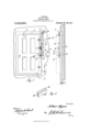
- Figure 1 represents the inside of a door, showing my improved alarm applied thereto.
- Figure 2 a section of the wall adjacent thereto, showing the door frame in elevation, and
- Fig. 3 a perspective view of the holding member.
- (1) represents the wall of a room having a door frame 2 mounted therein, to which is hinged the door 3.
- the attaching member 4 which may be a nail or screw, but which is preferably as here shown, a screw eye.
- a guiding member 5 such as a pulley or other inclosed member but is preferably a screw eye as here shown.
- the cable 10 running from the ring 9 to the fastening member 16 is of greater length than the distance from the ring to the fastening member, so that a certain amount of slack cable remains which is loosely wound about the fastening member to keep said cable in the groove of the push button center but when the door is opened this loosely wound slack portion of the cable will be drawn from the fastening member until only a few coils of the cable remainon said fastening member and these few coils will be drawn very tight and when the cable is drawn taut the ring 9 will have moved the desired distance as will be hereinafter described.
- the ring 9 rests upon the holding member 17 which may be two parallel short strips 18, producing a groove or space therebetween which is straddled by the ring 9, so that the cables 6 and 10 are in alinement with this groove while the ring rests upon the front faces of the members, and these front faces are farther removed from the face of the door jamb than the surfaces of the guide members, causing the cables to run at an angle from the guide members to the ring.
- a block 20 is utilized, this block being grooved or channeled as at 21 which is the same as that formed by the two parallel members 18, but by using a holding member as here described one screw may be passed through the bottom wall thereof and the holding member will be fastened in place.
- the alarm is then set. If the door is opened, the distance between the attaching member 4 and the guide 5 is increased which will cause the cable 6 to pull the ring 9 toward the guide 8 until said ring is passed over the ends of the holding member 17, at which time said ring will drop behind the ends of said holding member because of the guide 8 being closer to the door jamb than the holding member 17.
- the same device may be utilized upon the window, and when fastened to the upper sash will be exactly as shown for the door, so that any downward movement thereof will increase the distance between the fastening member 4 and the guide 5, but for use upon the lower sash the fastening means 4 would have to be above the guide 5 so that the distance between the two would be increased by any upward movement of the sash.
- a burglar alarm an electric bell, wires attached thereto and having a battery situated in their course, a push button attached to said wires, a push button center having a groove therein, a cable passing through said groove and having one end permanently fastened, another cable having one end attached to the door, a link for connecting said cables, and means on which said link operates for holding said link in a certain position after the door has been opened.
- a burglar alarm an electric bell, wires attached thereto and having a battery situated in their course, a push button attached to said wires, a push button center having a groove therein, a cable passing through said groove and having one end permanently fastened, another cable having one end attached to the door, a link for connecting said cables, and a holding member, said link resting upon the front face of said holding member and adapted to engage its end when the door is opened.
- a burglar alarm an electric bell, wires attached thereto and having a battery situated in their course, a push button at tached to said wires, a push button center having a groove therein, an attaching means, a pair of guide members, one of which is mounted upon each side of the push button, a cable secured to said attaching means and passing through said guides and the groove in the push button center, a fastening means attached to the door, a number of guide members mounted upon the door jamb, one of which is adjacent the fastening means, a cable secured to said fastening means and passing through the guide members, a ring to which the ends of the cables are fastened, and a holding member, the front face of which is a greater
Landscapes
- Physics & Mathematics (AREA)
- General Physics & Mathematics (AREA)
- Burglar Alarm Systems (AREA)
Description
' A. MYERS.
BURGLAR ALARM. APPLICATION FILED MAR. 30, 1911.
1,012,691. Patented Dec.26, 1911.
' 51mm vi /4%?) Wye/'15 COLUMBIA PLANO-GRAPH co wAsmNmo'v n c ARTHUR MYERS, OF PHILADELPHIA, PENNSYLVANIA.
BURGLAR-ALARM.
Specification of Letters Patent.
Patented Dec. 26, 1911.
Application filed March 30, 1911. Serial No. 617,849.
To all whom it may concern.-
Be it known that I, ARTHUR MYERS, a subject of Roumania, residing at Philadelphia, in the county of Philadelphia and State of Pennsylvania, have invented a certain new and useful Improvement in Burglar-Alarms, of which the following is a specification.
My invention relates to new and useful improvements in burglar alarms, and has for its object to provide an exceedingly sim ple and effective device of this character which may be applied to electric door bells which are already installed in houses or which may be independent thereof and when applied to either a door or window will cause an alarm to-be sounded should they be opened, and said alarm will continue to ring even though the cable which is attached to the door for operating the alarm, should be cut or broken.
A further object of, the invention is to produce a burglar alarm which will be simple in construction, inexpensive in the cost of manufacture and one in which, should the portion attached to the door or window become broken, may be readily repaired.
With these ends in view, this invention consists in the details of construction and combination of elements hereinafter set forth and then specifically designated by the claims.
In order that those skilled in the art to which this invention appertains may understand how to make and use the same, I will describe its construction in detail, referring by letter to the accompanying drawing forming a part of this specification, in which Figure 1, represents the inside of a door, showing my improved alarm applied thereto. Fig. 2, a section of the wall adjacent thereto, showing the door frame in elevation, and Fig. 3, a perspective view of the holding member.
In carrying out my invention as here embodied, (1) represents the wall of a room having a door frame 2 mounted therein, to which is hinged the door 3. To some suitable part of the door is fastened the attaching member 4, which may be a nail or screw, but which is preferably as here shown, a screw eye. In line with this attaching member upon the door frame 2, is placed a guiding member 5 such as a pulley or other inclosed member but is preferably a screw eye as here shown.
6 is a string, wire or other cable, one end of which is fastened to the attaching member 4, it then running through the button to a fastening member 16 at which point it is secured. The cable 10 running from the ring 9 to the fastening member 16 is of greater length than the distance from the ring to the fastening member, so that a certain amount of slack cable remains which is loosely wound about the fastening member to keep said cable in the groove of the push button center but when the door is opened this loosely wound slack portion of the cable will be drawn from the fastening member until only a few coils of the cable remainon said fastening member and these few coils will be drawn very tight and when the cable is drawn taut the ring 9 will have moved the desired distance as will be hereinafter described.
The ring 9 rests upon the holding member 17 which may be two parallel short strips 18, producing a groove or space therebetween which is straddled by the ring 9, so that the cables 6 and 10 are in alinement with this groove while the ring rests upon the front faces of the members, and these front faces are farther removed from the face of the door jamb than the surfaces of the guide members, causing the cables to run at an angle from the guide members to the ring. Another form of holding member is shown in Fig. 3, in which a block 20 is utilized, this block being grooved or channeled as at 21 which is the same as that formed by the two parallel members 18, but by using a holding member as here described one screw may be passed through the bottom wall thereof and the holding member will be fastened in place.
22 represent the wires running from the push button to the bell 23, having abattery 24 situated in their course. When this bell is utilized as the ordinary door bell the wires 25 are connected to the wires 22 and pass through the door jamb to a push button upon the outside.
In practice, when the end of the cable 6 is fastened to the attaching member 4 which is carried by the door, the alarm is then set. If the door is opened, the distance between the attaching member 4 and the guide 5 is increased which will cause the cable 6 to pull the ring 9 toward the guide 8 until said ring is passed over the ends of the holding member 17, at which time said ring will drop behind the ends of said holding member because of the guide 8 being closer to the door jamb than the holding member 17. As the ring is drawn to the ends of the holding member 17 the push button center '13 is pressed inward, forming a contact in the well known manner, causing the bell 23 to sound the alarm, and since the ring 9 is dropped behind the ends ofthe holding member 17 said bell will continue to ring even though the cable 6 is broken or cut and this cable is the one which would most likely be broken or cut as it works upon the 7 door and could be readily reached. By
winding a portion of the cable 10 loosely around the attaching means 16, said cable will be held comparatively taut over. the push button center and prevent its withdrawal from the groove, but when the door is opened the cable will be drawn tightly about the fastening means, permitting a suflicient amount of said cable to be removed from the fastening means to allow the ring to move over the holding member and en gage its ends.
The same device may be utilized upon the window, and when fastened to the upper sash will be exactly as shown for the door, so that any downward movement thereof will increase the distance between the fastening member 4 and the guide 5, but for use upon the lower sash the fastening means 4 would have to be above the guide 5 so that the distance between the two would be increased by any upward movement of the sash.
Of course I do not wish to be limited to the exact details of construction as here shown, as these may be varied within the limits of the appended claims without de-. parting from the'spirit of my invention.
Having thus fully described my invention, what I claim as new and useful, is
1. A burglar alarm, an electric bell, wires attached thereto and having a battery situated in their course, a push button attached to said wires, a push button center having a groove therein,a cable passing through said groove and attached to the door, and means for holding a portion of said cable tang should the other portion become severe 2. A burglar alarm, an electric bell, wires attached thereto and having a battery situated in their course, a push button attached to said wires, a push button center having a groove therein, a cable passing through said groove and having one end permanently fastened, another cable having one end attached to the door, means for fastening said cables together, and means engaged by the first named means for holding the first named cable taut afterthe' door is opened.
3. A burglar alarm, an electric bell, wires attached thereto and having a battery situated in their course, a push button attached to said wires, a push button center having a groove therein, a cable passing through said groove and having one end permanently fastened, another cable having one end attached to the door, a link for connecting said cables, and means on which said link operates for holding said link in a certain position after the door has been opened.
4. A burglar alarm, an electric bell, wires attached thereto and having a battery situated in their course, a push button attached to said wires, a push button center having a groove therein, a cable passing through said groove and having one end permanently fastened, another cable having one end attached to the door, a link for connecting said cables, and a holding member, said link resting upon the front face of said holding member and adapted to engage its end when the door is opened.
5. A burglar alarm, an electric bell, wires attached thereto and having a battery situated in their course, a push button at tached to said wires, a push button center having a groove therein, an attaching means, a pair of guide members, one of which is mounted upon each side of the push button, a cable secured to said attaching means and passing through said guides and the groove in the push button center, a fastening means attached to the door, a number of guide members mounted upon the door jamb, one of which is adjacent the fastening means, a cable secured to said fastening means and passing through the guide members, a ring to which the ends of the cables are fastened, and a holding member, the front face of which is a greater In testimony whereof, I have hereunto distance from the door jamb than the guide afiixed my signature in the presence of two 10 megllifers, tlfle COIlIlgCtilg ring resting upon subscribing Witnesses.
sai ront ace an a apted to engage the end of the holding member When the door ARTHUR MYERS is opened; causing the push button center Witnesses:
to complete the circuit and continuously ABRAHAM SABLE,
sound the alarm. I JOSEPH I. ORETTFRIED.
Copies of this patent may be obtained for five cents each, by addressing the Commissioner of Patents, Washington, D. O.
Priority Applications (1)
| Application Number | Priority Date | Filing Date | Title |
|---|---|---|---|
| US61784911A US1012691A (en) | 1911-03-30 | 1911-03-30 | Burglar-alarm. |
Applications Claiming Priority (1)
| Application Number | Priority Date | Filing Date | Title |
|---|---|---|---|
| US61784911A US1012691A (en) | 1911-03-30 | 1911-03-30 | Burglar-alarm. |
Publications (1)
| Publication Number | Publication Date |
|---|---|
| US1012691A true US1012691A (en) | 1911-12-26 |
Family
ID=3080999
Family Applications (1)
| Application Number | Title | Priority Date | Filing Date |
|---|---|---|---|
| US61784911A Expired - Lifetime US1012691A (en) | 1911-03-30 | 1911-03-30 | Burglar-alarm. |
Country Status (1)
| Country | Link |
|---|---|
| US (1) | US1012691A (en) |
-
1911
- 1911-03-30 US US61784911A patent/US1012691A/en not_active Expired - Lifetime
Similar Documents
| Publication | Publication Date | Title |
|---|---|---|
| US1012691A (en) | Burglar-alarm. | |
| US793775A (en) | Fire and burglar alarm. | |
| US1452500A (en) | Burglar-alarm apparatus | |
| US783399A (en) | Burglar-alarm. | |
| US945935A (en) | Window-alarm. | |
| US882570A (en) | Burglar-alarm. | |
| US787372A (en) | Burglar and fire alarm. | |
| US978269A (en) | Automatic burglar-alarm. | |
| US357416A (en) | Half to edw | |
| US368336A (en) | Burglar-alarm | |
| US1039142A (en) | Electric burglar-alarm. | |
| US594389A (en) | Burglar and fire alarm | |
| US277738A (en) | Ringing burglar-alarm | |
| US521239A (en) | Burglar-alarm | |
| US517547A (en) | Minthorne t | |
| US1211448A (en) | Time and burglar alarm. | |
| US605779A (en) | Burglar-alarm | |
| US547013A (en) | holding | |
| US1176521A (en) | Burglar-alarm. | |
| US309412A (en) | Burglar-alarm | |
| US315138A (en) | Burglar-alarm | |
| US870063A (en) | Burglar-alarm. | |
| US1078550A (en) | Burglar-alarm. | |
| US1060516A (en) | Burglar-alarm. | |
| US429503A (en) | Sash-holder |