US10125839B2 - Planar linkage, methods of decoupling, mitigating shock and resonance, and controlling agricultural spray booms mounted on ground vehicles - Google Patents
Planar linkage, methods of decoupling, mitigating shock and resonance, and controlling agricultural spray booms mounted on ground vehicles Download PDFInfo
- Publication number
- US10125839B2 US10125839B2 US15/299,383 US201615299383A US10125839B2 US 10125839 B2 US10125839 B2 US 10125839B2 US 201615299383 A US201615299383 A US 201615299383A US 10125839 B2 US10125839 B2 US 10125839B2
- Authority
- US
- United States
- Prior art keywords
- boom
- booms
- vehicle
- center
- mass
- Prior art date
- Legal status (The legal status is an assumption and is not a legal conclusion. Google has not performed a legal analysis and makes no representation as to the accuracy of the status listed.)
- Active, expires
Links
- 239000007921 spray Substances 0.000 title claims abstract description 41
- 238000000034 method Methods 0.000 title abstract description 20
- 230000035939 shock Effects 0.000 title abstract description 8
- 230000000116 mitigating effect Effects 0.000 title description 4
- 238000013016 damping Methods 0.000 claims description 46
- 239000000725 suspension Substances 0.000 abstract description 13
- 238000011068 loading method Methods 0.000 abstract description 9
- 238000010348 incorporation Methods 0.000 abstract description 2
- 238000006073 displacement reaction Methods 0.000 description 25
- 230000008901 benefit Effects 0.000 description 24
- 239000003570 air Substances 0.000 description 21
- 238000013461 design Methods 0.000 description 21
- 238000005507 spraying Methods 0.000 description 10
- 230000001133 acceleration Effects 0.000 description 8
- 230000006870 function Effects 0.000 description 7
- 239000007788 liquid Substances 0.000 description 7
- 230000008093 supporting effect Effects 0.000 description 7
- 230000008859 change Effects 0.000 description 6
- 239000012530 fluid Substances 0.000 description 6
- 125000004122 cyclic group Chemical group 0.000 description 5
- 230000000694 effects Effects 0.000 description 5
- 230000004044 response Effects 0.000 description 5
- 230000009471 action Effects 0.000 description 4
- 230000001066 destructive effect Effects 0.000 description 4
- 230000005484 gravity Effects 0.000 description 4
- 230000001939 inductive effect Effects 0.000 description 4
- 238000009428 plumbing Methods 0.000 description 4
- 238000006243 chemical reaction Methods 0.000 description 3
- 238000012986 modification Methods 0.000 description 3
- 230000004048 modification Effects 0.000 description 3
- 238000000429 assembly Methods 0.000 description 2
- 230000000712 assembly Effects 0.000 description 2
- 238000012937 correction Methods 0.000 description 2
- 230000007812 deficiency Effects 0.000 description 2
- 230000002950 deficient Effects 0.000 description 2
- 238000010586 diagram Methods 0.000 description 2
- 239000000463 material Substances 0.000 description 2
- 230000007246 mechanism Effects 0.000 description 2
- 239000002184 metal Substances 0.000 description 2
- 230000010355 oscillation Effects 0.000 description 2
- 230000032361 posttranscriptional gene silencing Effects 0.000 description 2
- 230000008569 process Effects 0.000 description 2
- 238000005086 pumping Methods 0.000 description 2
- 230000003134 recirculating effect Effects 0.000 description 2
- 239000012080 ambient air Substances 0.000 description 1
- 238000004458 analytical method Methods 0.000 description 1
- 238000013459 approach Methods 0.000 description 1
- 238000005452 bending Methods 0.000 description 1
- 230000009194 climbing Effects 0.000 description 1
- 238000004891 communication Methods 0.000 description 1
- 230000006835 compression Effects 0.000 description 1
- 238000007906 compression Methods 0.000 description 1
- 238000011217 control strategy Methods 0.000 description 1
- 238000013400 design of experiment Methods 0.000 description 1
- 238000005516 engineering process Methods 0.000 description 1
- 239000003337 fertilizer Substances 0.000 description 1
- 239000004519 grease Substances 0.000 description 1
- 230000012447 hatching Effects 0.000 description 1
- 239000004009 herbicide Substances 0.000 description 1
- 230000001976 improved effect Effects 0.000 description 1
- 230000006872 improvement Effects 0.000 description 1
- 239000002917 insecticide Substances 0.000 description 1
- 238000002955 isolation Methods 0.000 description 1
- 230000008407 joint function Effects 0.000 description 1
- 239000003562 lightweight material Substances 0.000 description 1
- 239000000696 magnetic material Substances 0.000 description 1
- 238000012423 maintenance Methods 0.000 description 1
- 238000004519 manufacturing process Methods 0.000 description 1
- 238000012067 mathematical method Methods 0.000 description 1
- 229920001296 polysiloxane Polymers 0.000 description 1
- 230000000452 restraining effect Effects 0.000 description 1
- 238000005096 rolling process Methods 0.000 description 1
- 239000000126 substance Substances 0.000 description 1
- 238000013519 translation Methods 0.000 description 1
Images


Classifications
-
- F—MECHANICAL ENGINEERING; LIGHTING; HEATING; WEAPONS; BLASTING
- F16—ENGINEERING ELEMENTS AND UNITS; GENERAL MEASURES FOR PRODUCING AND MAINTAINING EFFECTIVE FUNCTIONING OF MACHINES OR INSTALLATIONS; THERMAL INSULATION IN GENERAL
- F16F—SPRINGS; SHOCK-ABSORBERS; MEANS FOR DAMPING VIBRATION
- F16F7/00—Vibration-dampers; Shock-absorbers
- F16F7/10—Vibration-dampers; Shock-absorbers using inertia effect
- F16F7/104—Vibration-dampers; Shock-absorbers using inertia effect the inertia member being resiliently mounted
-
- F—MECHANICAL ENGINEERING; LIGHTING; HEATING; WEAPONS; BLASTING
- F16—ENGINEERING ELEMENTS AND UNITS; GENERAL MEASURES FOR PRODUCING AND MAINTAINING EFFECTIVE FUNCTIONING OF MACHINES OR INSTALLATIONS; THERMAL INSULATION IN GENERAL
- F16F—SPRINGS; SHOCK-ABSORBERS; MEANS FOR DAMPING VIBRATION
- F16F9/00—Springs, vibration-dampers, shock-absorbers, or similarly-constructed movement-dampers using a fluid or the equivalent as damping medium
- F16F9/02—Springs, vibration-dampers, shock-absorbers, or similarly-constructed movement-dampers using a fluid or the equivalent as damping medium using gas only or vacuum
-
- A—HUMAN NECESSITIES
- A01—AGRICULTURE; FORESTRY; ANIMAL HUSBANDRY; HUNTING; TRAPPING; FISHING
- A01C—PLANTING; SOWING; FERTILISING
- A01C23/00—Distributing devices specially adapted for liquid manure or other fertilising liquid, including ammonia, e.g. transport tanks or sprinkling wagons
- A01C23/04—Distributing under pressure; Distributing mud; Adaptation of watering systems for fertilising-liquids
- A01C23/047—Spraying of liquid fertilisers
-
- A—HUMAN NECESSITIES
- A01—AGRICULTURE; FORESTRY; ANIMAL HUSBANDRY; HUNTING; TRAPPING; FISHING
- A01G—HORTICULTURE; CULTIVATION OF VEGETABLES, FLOWERS, RICE, FRUIT, VINES, HOPS OR SEAWEED; FORESTRY; WATERING
- A01G25/00—Watering gardens, fields, sports grounds or the like
- A01G25/09—Watering arrangements making use of movable installations on wheels or the like
-
- A—HUMAN NECESSITIES
- A01—AGRICULTURE; FORESTRY; ANIMAL HUSBANDRY; HUNTING; TRAPPING; FISHING
- A01M—CATCHING, TRAPPING OR SCARING OF ANIMALS; APPARATUS FOR THE DESTRUCTION OF NOXIOUS ANIMALS OR NOXIOUS PLANTS
- A01M7/00—Special adaptations or arrangements of liquid-spraying apparatus for purposes covered by this subclass
- A01M7/005—Special arrangements or adaptations of the spraying or distributing parts, e.g. adaptations or mounting of the spray booms, mounting of the nozzles, protection shields
- A01M7/0053—Mounting of the spraybooms
-
- F—MECHANICAL ENGINEERING; LIGHTING; HEATING; WEAPONS; BLASTING
- F16—ENGINEERING ELEMENTS AND UNITS; GENERAL MEASURES FOR PRODUCING AND MAINTAINING EFFECTIVE FUNCTIONING OF MACHINES OR INSTALLATIONS; THERMAL INSULATION IN GENERAL
- F16F—SPRINGS; SHOCK-ABSORBERS; MEANS FOR DAMPING VIBRATION
- F16F9/00—Springs, vibration-dampers, shock-absorbers, or similarly-constructed movement-dampers using a fluid or the equivalent as damping medium
- F16F9/32—Details
- F16F9/38—Covers for protection or appearance
-
- A—HUMAN NECESSITIES
- A01—AGRICULTURE; FORESTRY; ANIMAL HUSBANDRY; HUNTING; TRAPPING; FISHING
- A01M—CATCHING, TRAPPING OR SCARING OF ANIMALS; APPARATUS FOR THE DESTRUCTION OF NOXIOUS ANIMALS OR NOXIOUS PLANTS
- A01M7/00—Special adaptations or arrangements of liquid-spraying apparatus for purposes covered by this subclass
- A01M7/005—Special arrangements or adaptations of the spraying or distributing parts, e.g. adaptations or mounting of the spray booms, mounting of the nozzles, protection shields
- A01M7/0071—Construction of the spray booms
- A01M7/0078—Construction of the spray booms including break-away devices
-
- Y—GENERAL TAGGING OF NEW TECHNOLOGICAL DEVELOPMENTS; GENERAL TAGGING OF CROSS-SECTIONAL TECHNOLOGIES SPANNING OVER SEVERAL SECTIONS OF THE IPC; TECHNICAL SUBJECTS COVERED BY FORMER USPC CROSS-REFERENCE ART COLLECTIONS [XRACs] AND DIGESTS
- Y10—TECHNICAL SUBJECTS COVERED BY FORMER USPC
- Y10T—TECHNICAL SUBJECTS COVERED BY FORMER US CLASSIFICATION
- Y10T403/00—Joints and connections
- Y10T403/32—Articulated members
- Y10T403/32008—Plural distinct articulation axes
Definitions
- the present invention relates to a planar linkage, to the support, isolation and dynamic control of spray booms connected to a tractor, trailer or other vehicle for the purpose of agricultural spraying and to a gas tension spring.
- Agricultural fields are often sprayed with various spraying solutions, such as herbicides, insecticides, fertilizers, etc.
- Sprayers for this purpose are required to have a wide span booms furnished with plumbing and multiple spray nozzles, for the liquids being sprayed, at defined intervals across the boom's span: While contemporary span widths may extend as wide as 120 through to 162 feet, with even wider spans predicted in the future. However, when not being used for spraying, these wide-span booms are required to fold away to a stowed position, typically along either side of the vehicle, to permit the vehicle to navigate field entrance gates and traverse tracks, roads or highways, without exceeding either practical or legal width limits.
- the vehicles which employ these foldable wide span booms may take the form of farm tractors, trailers or specialist vehicles fitted with chemical tanks or reservoirs to carry the liquids being sprayed, and the spray booms themselves may be fitted typically at either the front or rear of such vehicles on each side of the vehicle on a “center-rack” which also supports plumbing and spray nozzles across the short distance that spans the width of the vehicle itself.
- this center-rack along with the booms attached to it, can be elevated or lowered on a four-bar linkage and actuator(s) or other suitable means, to adjust and set the boom/nozzles spray height to achieve to most effective crop spray coverage.
- the booms are arranged to pivot about essentially vertical axes, so that they may be rotated in angular displacement through 90° or so from the spraying position which is normal to the vehicle's longitudinal axis, to the folded, stowed position essentially parallel the vehicle's longitudinal axis when viewed in plan. Because of the great length of the booms, it is customary for the booms to be further folded via hinge points located at around the mid-semi-span of each boom. In some cases, where very high span booms are used, further folding hinge points may be used to shorten the folded boom length.
- the folded boom length may be shortened by having the outer semi span of each boom retract telescopically in to the inner boom semi-span.
- a combination of telescopic and folding boom segments may be employed.
- the folding and unfolding action of the booms is conducted by means of actuators, more commonly, hydraulically operated.
- spray booms are commonly designed to be operated in the part-folded position, with the outboard sections folded alongside the inboard sections.
- a boom system might be referred to as a 132-60, or other similar designation, implying in this case a full span of 132 feet, and a semi-folded span of 60 feet.
- the loads imposed on the booms during operation have a significant effect on their structural design. It is the mass of the booms' structure itself along with its supported loads including pipework, plumbing, spray nozzles, valves, filters, hydraulic cylinders and sundry masses such as touch-down wheels that is responsible for generating the greater part of its structural loading.
- the vehicle's movement about the roll and yaw axes are potentially the greatest.
- the booms effective moment of inertia about these axes can be defined as the sum of an infinite number of discrete mass segments each of whose moment is the product of the segment mass and the square of its distance from the roll axis: Therefore because of the large boom span and the distance-squared function, the polar moment of inertia of the deployed booms is truly massive, notwithstanding that the booms' outboard sections can be comparatively light.
- One way that this is currently done is to arrange to allow angular displacements to readily occur between each inner boom and the center-rack at a lower, acceptable level of force, by having a lower longitudinal pivot between the boom and center-rack.
- Each boom is then maintained in an essentially horizontal position by a hydraulic cylinder that attaches to an upper inboard boom attachment point at one end and to an upper center rack attachment at the other end.
- a level of compliance (springing) in angular roll displacement can be achieved between each of the booms and the center-rack/vehicle.
- each boom can be controlled independently in angular displacement about the vehicle's roll axis; and this can be used, in conjunction with ground-height sensors mounted, typically, at intervals across the span of the booms, as part of a system to control and maintain to booms essentially parallel to the ground during operation. It also permits control recognition of sudden vehicular roll movements and allows active correction of the boom position relative to the vehicle's roll position when such spurious movements occur. While this has proven to be effective, at least to some extent, the active control response is often considered to be too slow to be fully effective in mitigating the movements and forces caused by sudden roll excursions of the vehicle.
- the vehicle speed may have to be reduced to unacceptably slow levels to allow time for the corrective response to take place, or loss of effective control of the outboard boom section heights may take place, giving rise to unnecessarily high boom forces in roll as well as defective spray application and may even cause the boom tips to impact the ground.
- the foregoing active roll correction system is sometimes further improved by linking the hydraulic lines feeding two upper boom hydraulic cylinders on either side of the vehicle together via pressure relief valves:
- the relief valves In the event that the roll forces imposed on the cylinders gives rise to a hydraulic pressure differential between the cylinders that exceeds a given pre-set level, the relief valves then open and hydraulic fluid is transferred automatically between the two cylinders, allowing the vehicle to effectively roll relative to the pair of booms en-masse without having to react further forces.
- This may well be an improvement, but it is not a full solution since typically outer boom height control is still rendered somewhat ineffective in practice.
- a torsionally resilient connection may be used at this point and this may take the form of torsionally acting spring elements or other means to help keep the boom in general horizontal alignment, relative to the vehicle, without the vehicle's short term roll movements significantly deflecting the booms in roll, or generating excessively high reaction forces in the booms at their attachment to the center-rack.
- a further variation on this theme is for the center-rack to be supported by a linkage that results in an effective virtual longitudinal pivot point whose virtual pivotal axis is above the center of gravity of the combined booms and center rack, such that the booms benefit by the pendular stability so generated, at least when travelling on fairly level terrain.
- the upper boom attachment hydraulic cylinders, or a single hydraulic cylinder and linkage serving to replace them, then acts to change the angular displacement of the pair of booms in roll relative to each other, rather than relative to the vehicle.
- a second, independent, control action may then be employed to control the overall position of the linked pair of booms in roll, relative to the ground reference, given by the previously mentioned boom height sensors.
- the booms may not only have the roll forces, otherwise imposed on them by the vehicle movement over undulating or rough ground surfaces, reduced or effectively eliminated, but a comprehensive boom height control system can effectively permit the booms to be maintained at an essentially fixed mean-height above the ground; and also that this mean height can be maintained even when traversing the rounded crest of a hill or ridge, or along a gully by virtue of being able to control the roll position of the booms relative to each other at the same time.
- the spray booms are better able to follow, at an essentially constant mean height above the ground, any gently varying contours of the ground that occurs across the span of the booms during operation.
- the active control force can be applied to control the mean angular position of the linked pair of booms relative to the ground: one is to react the controlling actuator in roll against the vehicle, while typically incorporating an interposed low spring-rate compliant element, such that the reaction force is rendered at least somewhat independent of the relative angular roll axis position of the vehicle: While the other is to change the lateral position of the combined booms' center of gravity relative to the center-rack's roll pivot support, such that gravitational reaction is used.
- This latter concept has the advantage of deriving the boom roll control forces entirely independently of the vehicle's instantaneous roll position.
- one boom design feature that has become almost universally adopted by current wide-span spray boom designs is the “breakaway”.
- This is typically a vertical hinge pivot system applied such that the last outboard 12 to 15 feet or so of the boom, up to the boom tip itself, can pivot back to alleviate damage if the outermost extremities of the boom accidently contact an obstacle, or contact the ground.
- the breakaway section is centered in the fully extended position by pin inclination and gravity or by spring force, or both, so that upon contact with an object, the breakaway section fold back to avoid damage, and re-centers automatically when the object or ground contact has passed.
- touch-down wheels Another practical adaption often used on wide-span agricultural spay booms are so called “touch-down” wheels. These wheels are attached on legs, one on each boom semi-span below and slightly forward of the booms to avoid interference with the spray pattern, fairly well outboard along the boom span. Their purpose is to prevent the booms from encroaching too close to, or touching the ground in the event of the control system failing to adequately maintain the correct height position of the boom. While such touch-down wheels may prevent obvious damage to the booms in the event the height control system failure, their inclusion might be considered as indication of the inadequacies of current spray boom/control system design and control methodologies and the need to address them.
- Structural design is of vital importance to both the affordability and durability of wide-span spray booms. In this respect it is not only the absolute structural strength of the booms that is relevant, but also, and perhaps more critically, the fatigue strength, which on metal boom structures, particularly welded metal boom structures, usually defines the boom's usable life. In this respect the amplitude of the cyclic fatigue loadings applied to the boom, either as imposed loads (from bumps in the terrain reacting the inertia of the boom structure, for example) or as resonance generated loads (from structural modal resonance response) are of great importance.
- semi-active control of the longitudinal and yaw accelerations is also currently practiced, while automatically self-leveling the booms relative to the sensed ground position at a pre-set spray height, combined with compliant boom suspension, effectively results in semi-active vertical boom suspension, there still remain some serious deficiencies in structural and fatigue boom design capabilities.
- the optimal structural design of spray booms typically results in a triangulated braced truss-structure for several reasons.
- the truss type structure is one of the strongest, lightest and most rigid configurations, and secondly, when in the folded position along both sides of the vehicle, the open lattice frame of the truss structure allows the driver a fairly high level of visibility through the structure itself, so enabling safer operation, particularly on roads and highways.
- the open lattice structure also permits ready access to any plumbing, hydraulics, electrical and communication lines, sensors etc. for maintenance or modular adaptability.
- wide-span spray booms be designed using lightweight high-strength materials, so that the booms' span can be maximized while the structural loads, resulting largely from the boom structural mass, can be kept with the limits defined by the operational life requirements.
- boom system It is desirable for the boom system to be able to accurately maintain the optimal, near constant, spray height above the ground, and to follow the smooth contours and undulations in the ground surface profile in span at the highest practical vehicle spraying speed.
- the spray boom structure be of the truss or lattice type, so that the vehicle driver's visibility through the structure is not significantly impeded when the booms are in the folded position along both sides of the vehicle.
- the present invention serves to overcome these deficiencies.
- the current invention discloses several methodologies that mitigate shock loading and propensity to resonance in agricultural spray boom structures. These include a new form of near-planar linkage instrumental in decoupling the boom assembly from the vehicle in pitch, heave and roll. This serves to permit further aspects of the invention to: Use the combined mass of the booms and center section as the tuned mass of a tuned mass damper that can counter the eigenfrequency of the boom system in vertical resonance (flapping): Act as an enabling part of a boom compliant suspension system to mitigate shock loadings otherwise imposed on the boom system, and: Act as an enabling part of an active boom height and roll control systems to permit the accurate navigation of the boom over undulating terrain.
- the planar linkage also has application to other devices and uses.
- wide-span spray booms of the present invention are designed using lightweight high-strength materials. This allows the boom's span to be maximized while the structural loads, resulting largely from the boom structural mass, can be kept with the limits defined by the operational life requirements.
- both the boom-span and vehicle speed be maximized; notwithstanding that both these parameters significantly increase the propensity of the boom structure to flexure and resonance.
- the fatigue strength of the structure in addition to the limit-load strength of the boom structure should be accounted for in a boom design.
- an advantage of the present invention is that structural resonance, particularly in the vertical and longitudinal vehicle axis directions, can be eliminated or reduced to acceptable levels, particularly at the resonant Eigen-frequencies.
- the resulting fatigue strength and structural strength allow for the booms to have a greater width and the vehicle to travel at a faster speed. This results in greater coverage per unit time.
- the spray boom structure is of the truss or lattice type, so that the vehicle driver's visibility through the structure is not significantly impeded when the booms are in the folded position along both sides of the vehicle.
- a near planar linkage is provided according to one aspect of the present invention.
- the near planar linkage can carry weights in a plane without the need for direct contact points such as rollers. It is understood that the motion of an object connected to the linkage can be nearly planar.
- the boom system is able to accurately maintain the optimal, near constant, spray height above the ground, and can follow the smooth contours and undulations in the ground surface profile in span at the highest practical vehicle spraying speed.
- methodologies to mitigate otherwise excessive loads from being imposed on the boom's structure by the vehicle's movement over rough or uneven ground, in the vertical or longitudinal axis directions due to the booms' inertia reacting the vehicle's vertical, longitudinal and yaw displacements are provided.
- the near constant force element is coupled with dampers in parallel to eliminate low rate of oscillation in booms. Hence, the entire boom is damped.
- the angle of the center rack (and hence the booms) can be controlled by an internal pump.
- a controller controls an internal pump to direct air (and hence change pressure) to rotate the boom assembly to the left or right side boom. This is accomplished without adding or removing air (or a gas or a working fluid) from the system.
- the internal pump switches direction of pumping as often as needed to maintain the desired boom angles.
- a positional link is provided.
- the positional link can tilt a secondary section of boom relative to the first section of the boom to maintain a desired spray height. Articulation can be done in real time by the use of sensors and a controller.
- a tension gas spring is provided.
- the tension gas spring inverts action a compression gas strut to form a tension gas spring. This allows an embodiment of the present invention to pull two objects towards each other.
- Damping is provided as two arms pull back towards each other in latter portion of return of the gas strut. It is appreciated that there isn't any appreciable damping as the arms separate from each other, thereby allowing freedom of outward motion.
- two tension gas springs can be used with a breakaway section of a boom to turn the break away into a tuned mass damper.
- one of the two tension gas springs can first separate (without damping) and then provide a damping effect upon the latter part of the return.
- there will be one active damper and one inactive damper depending on the direction of the swing of the breakaway relative the adjacent boom section.
- breakaway section as a tuned mass damper is that it does not add appreciable weight to the boom.
- a tuned mass damper can be bolted or otherwise connected to the boom. This advantageously can address specific problems in primary and secondary (or tertiary) modes remedially (i.e. if they appear).
- the tuned mass damper can be designed so that a single mass can damp in both the vertical and horizontal directions.
- the tuned mass dampers can be passive or active.
- an active damper such as a coil and magnetized mass
- the user can selectably turn on the damper as necessary.
- FIG. 1 is a perspective view of an existing agricultural spray vehicle and boom system in operating position to which the current invention may be applied.
- FIG. 2 is a perspective view of an existing agricultural spray vehicle in folded and boom system, to which the current invention may be applied, with the booms in the stowed position.
- FIG. 3 is a perspective view of an embodiment of a near planar linkage.
- FIG. 4 is a side view of the embodiment illustrated in FIG. 3 .
- FIG. 5 is similar to FIG. 4 , but shows a strut moved away from the centered position but maintaining a position in a similar plane.
- FIG. 6 is a rear perspective view of the embodiment illustrated in FIG. 3 .
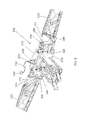
- FIG. 7 is similar to FIG. 6 , but shows a spherical joint at the distal end of the strut in an alternative orientation.
- FIG. 8 is a perspective view of an embodiment of a support assembly including a center rack incorporating near planar linkages.
- FIG. 9 is an alternative view of the embodiment shown in FIG. 8 .
- FIG. 10 is an alternative view of the embodiment shown in FIG. 8 .
- FIG. 11 is an alternative view of the embodiment shown in FIG. 8 .
- FIG. 12 is a perspective view showing an embodiment of a positional connector of the present invention.
- FIG. 13 is similar to FIG. 12 , but shows the second boom section in an elevated angle relative the primary boom section.
- FIG. 14 is similar to FIG. 12 , but shows the second boom section in a declined angle relative the primary boom section.
- FIG. 15 is a high level flow diagram of the controller operation.
- FIG. 16 is a side view of an embodiment of a tension gas spring.
- FIG. 17 is a perspective view of the embodiment illustrated in FIG. 16 .
- FIG. 18 is a side view showing the internal components of the embodiment illustrated in FIG. 16 .
- FIG. 19 is a perspective view of a breakaway tuned mass damper.
- FIG. 20 is similar to FIG. 19 , but shows the breakaway swung in a first direction.
- FIG. 21 is similar to FIG. 19 , but shows the breakaway swung in a second direction.
- FIG. 22 is a perspective view of an embodiment of a tuned mass damper.
- FIG. 23 is a perspective view of an alternative embodiment of a tuned mass damper.
- FIG. 24 is a perspective view of an alternative embodiment of a tuned mass damper.
- FIG. 24A is similar to FIG. 24 but shows a cover in place.
- FIG. 25 is a perspective view of an alternative embodiment of a tuned mass damper.
- FIG. 25A is similar to FIG. 25 but shows a cover in place.
- FIG. 26 is a schematic view of a boom assembly with a left and right boom in a straight position.
- FIG. 27 is similar to FIG. 26 , but shows the booms articulated to match the contour of the ground beneath.
- FIG. 28 is similar to FIG. 26 , but shows the booms articulated to match the contour of the ground beneath.
- FIGS. 1 and 2 show the booms mounted in position on a vehicle.
- FIG. 1 shows them as they would be in the deployed in the full-span and part-span operating position when used for spraying crops
- FIG. 2 shows the invention in its folded position as it would be used for driving to and from the fields being sprayed, maneuvering through field entrances gates, along tracks or on roads or highways.
- the booms 110 and 120 shown in the various embodiments of the current invention comprise three primary identifiable segments: The primary or inner boom, the secondary or outer boom, which incorporates a breakaway.
- the current invention incorporates multiple near planar linkages, or near planar link mechanism, 20 . These linkages are seen in FIGS. 3-7 .
- Each near planar linkage 20 has a body 30 with three body joints 31 , 32 and 33 .
- a center arm 40 is provided having a base 41 with three center arm joints 42 , 43 and 44 .
- a strut 50 upstands from the base 40 .
- the strut 50 has a proximal end 51 and a distal end 52 .
- a spherical joint 53 is at the distal end 52 of the strut.
- a link 60 is provided.
- a spherical joint 62 is at a first end 61 of the link, and a spherical joint 64 is at the second end 63 of the link.
- a link 70 is provided.
- a spherical joint 72 is at a first end 71 of the link, and a spherical joint 74 is at the second end 73 of the link.
- a link 80 is provided.
- a spherical joint 82 is at a first end 81 of the link, and a spherical joint 84 is at the second end 83 of the link.
- the links 60 , 70 and 80 interconnect the body 30 and center arm 40 .
- the first end spherical joint 62 of link 60 is connected to the first body joint 31 .
- the first end spherical joint 72 of link 70 is connected to the second body joint 32 .
- the first end spherical joint 82 of link 80 is connected to the second body joint 33 .
- the second end spherical joint 64 of link 60 is connected to the center arm joint 42 .
- the second end spherical joint 74 of link 70 is connected to the center arm joint 43 .
- the second end spherical joint 84 of link 80 is connected to the center arm joint 44 .
- center arm 40 can more relative the body 30 .
- the distal end 52 of the strut 50 moves generally in an approximate plane 90 .
- the central arm in one example can have a length of about 12 inches measured from the center of the spherical joint at the distal end to the plane of the pitch circle diameter (PCD) of the three other spherical joints at its large end.
- the link lengths center to the center of the spherical joints can be approximately 0.63; the center rod lard end PCD of the three spherical joints is approximately 0.67; and the large ring PCD of the three spherical joints is approximately 1.17.
- the near planar linkage comprises three links each of which is attached at one end by a spherical joint to a main body or support 30 at three approximately equi-distant attachment locations, and to one end of a mid-positioned, longer strut, via three approximately equi-spaced spherical joints.
- the center strut having the three links attached at one end as shown, and a single spherical joint at its distal end, has a longer distance between the plane of the pitch circle diameter of the spherical attachments at its large end to the center of the spherical joint at its distal end, than the length of the three links between their spherical joint centers:
- the pitch circle diameter of the spherical attachments on the main support is larger than the pitch circle diameter of the three spherical attachments at the end of the center strut.
- the length of the three links, spherical joint center to spherical joint center, is less than the pitch circle diameter of the centers of the three spherical joints on the larger end of the center-strut.
- the path that the center of the spherical joint at the distal end of the center-strut follows always remains closely planar to the plane that passes through the pitch circle diameter of the centers of the three spherical joints on main support.
- the mathematical method by which the geometry of the near-planar linkage is generated therefore one of iterative “Design of Experiments” applied typically using computing processes such as Matlab, Mathcad or bespoke computer programming.
- a support assembly 150 is provided to connect to a vehicle 101 four bar linkage 102 .
- the vehicle has a lift actuator 102 .
- the vehicle can have a first boom 110 with an angle actuator 111 for controlling an angle of the boom relative to the center rack and a second boom 120 with an angle actuator 121 for controlling an angle of the boom relative to the center rack.
- the support assembly 150 has a center rack support frame 160 .
- Support frame 160 has four connectors 161 , 162 , 163 and 164 .
- a center rack 170 is further provided having a top 171 , a bottom 172 , sides 173 and 174 , a front 175 and a rear 176 .
- a plurality of near planar linkages preferably four such linkages 180 , 181 , 182 and 183 , are provided. The four linkages are removably secures to the connectors of the support frame, wherein the center rack can move within a plane relative the support assembly without appreciably changing the distance between the components, namely the support frame 160 and the center rack 170 .
- a controller 200 for driving pump 220 .
- a reservoir 240 connected to an air bag 250 with a conduit and a damper 260 parallel with the expansion axis of the bag is further provided.
- a reservoir 2770 connected to an air bag 280 with a conduit, and a damper 290 parallel with the expansion axis of the bag is further provided. It is appreciated that the volume of the reservoirs compared to the distance the bags are inflated result in a near constant force element being provided to support the booms.
- the conduits between the reservoirs and bags can be located inside of other components or outside.
- the pump 220 can rapidly change direction causing the left or right side bags to selectably inflate or deflate (without changing the amount of gas in the system) and accordingly raise the left boom or right boom angularly relative via center rack positioning while the opposite boom is lowered angularly.
- Height sensors 300 are preferably located at the root end of the primary section, the outboard end of the secondary section and the outboard end of the breakaway section on each side boom. Hence, it is preferred to have six sensors. Of course, the number and location of the sensors 300 could change without departing from the broad aspects of the present invention.
- a pressure sensor 310 can also be provided to measure pressure on each side of the center rack within the reservoirs.
- a center rack 170 incorporating four of these planar linkages 180 , 181 , 182 and 183 , one at each corner, is provided.
- Each of these planar linkage center struts are attached, via the spherical joint at the distal end of the center-strut, to the support frame connected to the vehicle by the conventional four-bar lift linkage.
- the center-rack's mass were to be suitably supported, then it would be free to move vertically, horizontally and in angular translation about the vehicle's longitudinal axis, within the movement limitations of the planar linkages, while being constrained in all other degrees of freedom. While four planar linkages are shown, the present invention is not limited to utilizing four such linkages.
- the center rack 170 with booms attached being restrained by the four planar linkages as described, above, but with the weight of the boom assembly being reacted by two resilient suspension elements.
- These suspension elements can be mechanical springs, gas struts, liquid springs, hydraulic struts connected to compressed gas accumulators to act as springs, air springs, Near Constant Force (NCF) elements or any other type of resilient element that would reduce the shock loads that would otherwise be imposed on the boom assembly by vertical or roll displacements of the vehicle.
- NCF Near Constant Force
- These two spring elements may also be mounted in parallel with dampers, in much the same way that car suspension springs and dampers are configured to prevent resonance of the suspended mass (the center-rack and booms) by converting resonance momentum into heat, and dissipating it to their surroundings.
- the spring elements are gas springs configured to act as low K springs, that is, having a very small increase in spring force with displacement. This is achieved by the entrapped volume of the springs being large in relation to the swept volume displaced for a given spring movement.
- These gas springs 250 and 280 may take the form of air-bags similar to those often used for heavy truck and trailer suspension systems, but to increase the displacement/volume ratio, an additional closed reservoir volume may be attached to the airbag via a large bore connecting pipe (to minimize flow losses). Configured in this way, the effective K value of air springs may be lowered to the point that the spring system may be regarded as a Near Constant Force (NCF) element.
- NCF Near Constant Force
- Very low spring rate and NCF elements are advantageous in isolating or decoupling the suspended mass of the boom system from spurious movements of vehicle, but since they have little or no convergent restoring force, they require some form of active control to keep the boom system with the planar linkages limits of operation.
- any lateral forces that would otherwise cause the center-rack and booms to displace sideways under lateral accelerations imposed by the differential vertical movements of the wheels on either side of the vehicle, combined with the height of the boom and center-rack system above the ground, may be countered by spring elements and dampers, positioned to act laterally to restrain the center-rack relative to the center-rack support frame.
- the vertical position of these spring restraints may be constrained to be approximately coincident with the combined booms/center-rack assembly vertical center of mass in order to minimize spurious vertically acting forces from being imposed on the center-rack under lateral loadings or in side slope operation.
- two airbag spring elements instead of the single restraining spring are mounted at each side of the center-rack to restrain it.
- Two airbag type low spring (K) rate or NCF elements supporting the suspended mass of the center-rack and boom system can be provided.
- Height level sensors are fitted to each side of the center-rack, so that the height of each end of the center rack relative to the center-rack's support frame can be determined; accordingly their two signals can be computed to provide a combined mean rack height position. That is to say that the mean height level can be known, irrespective of the any angular displacement in roll between the decoupled center rack and boom system and the vehicle mounted boom support frame.
- the (typically) two actuators (usually hydraulic cylinders) that are fitted to the vehicle's four-bar linkage that raise and lower the center-rack and boom assemblies en-mass, are fitted with positional transducers (typically linear transducers) that enable the center-rack height position to be computed at any time.
- the two inner booms are furnished with a multiplicity of ground proximity height sensors 300 , with at least one sensor at each end of each inner or primary boom section, to measure the height above the ground.
- the secondary and breakaway boom sections are also fitted with ground height proximity sensors: At least one at, or towards the outboard end of the secondary boom section, or on the breakaway section, or both.
- pressure sensors are fitted to each of the air bags to measure the dynamic air pressure within them, or force sensors are used to measure the dynamic force being applied or reacted by each of the two air bags into the boom structure.
- the enclosed volumes of the two airbag springs are interconnected by a large bore tube and a high throughput, bi-directional, positive displacement air pump 220 , such as a Roots pump, is interposed in this interconnecting line, such that when driven in one direction of rotation, air is displaced from the left side airbag into the right side air bag, and when rotated in the opposite direction, air is pumped in the opposite direction, from the right side airbag into the left side air bag.
- a high throughput, bi-directional, positive displacement air pump 220 such as a Roots pump
- a further, smaller positive displacement leveling pump 210 serves to pressurize the whole boom suspension system, while control valves are fitted to operate in conjunction with the leveling pump to increase or decrease the mean pressure within the enclosed volume of air within the airbags, interconnecting pipe and bi-directional positive displacement pump.
- the entire boom system is supported by the two airbag springs, which are pressurized by the leveling pump to lift the center-rack and booms to the correct mean height to optimize the available movement of the four planar linkages.
- the leveling pump may be driven electrically from the vehicle's electrical supply, or driven by a hydraulic motor from the vehicles hydraulic supply.
- the leveling pump may exhaust into a pressurized air reservoir or accumulator from which the control system monitors and controls the pressurized air leveling supply to the enclosed boom suspension system by means of the valves mentioned earlier. Either way, the leveling operation may be controlled electronically using signals processed from positioning sensors mounted between the center-rack and the vehicle mounted support frame to control the pressurized airflow into and out of the enclosed system volume.
- a mechanically operated leveling valve as used to self-level the ride-height of commercial vehicles may be employed.
- the inertia of the booms will typically cause the boom movement to pass the set point, whereupon the direction of rotation of the positive displacement pump will be reversed to correct, and the booms will continuously be “balanced” in this manner, back and forth, although almost imperceptibly, such that the inner boom sections will remain at equal height above the ground on both sides of the vehicle, irrespective of the undulations and topographical contour changes of the ground profile.
- each of the two secondary boom sections is arranged to pivot in the region of their folding hinge point to the inner, or primary boom sections, upwards and downwards about longitudinally disposed pivot axes (in the operating mode): That is, that the primary and secondary boom sections can be articulated relatively to each other to increase or decrease their dihedral/anhedral angle as required to maintain the secondary at the correct mean height above the ground irrespective of the complex and varying span-wise contours of the ground, and the dihedral/anhedral positioning of the inboard boom sections which result from their own contour following capabilities.
- a positional connector 350 is provided.
- the connector 350 connects a primary boom section 360 with longitudinal axis 361 to a secondary boom section 371 with longitudinal axis.
- a folding actuator 380 is shown schematically, which is used to fold the secondary boom section relative to the first boom section.
- a top pivot 390 and a bottom pivot 400 are provided.
- the top pivot is a pivotal connection of a fixed length.
- the bottom pivot 400 has an actuator 401 and a positional control 402 .
- the pivot is rotational as well as linearly adjustable.
- the actuator can have a predetermined stroke, wherein at one end of the stroke the secondary boom section 370 is held on an inclined plane or orientation relative to the primary boom section 360 .
- the secondary boom section 370 is held at a declined plane or orientation relative to the primary boom section 360 .
- the secondary boom section 370 can further be oriented wherein its longitudinal axis 371 is generally parallel to the longitudinal axis 361 of the primary boom section at a point intermediate the two actuator stroke ends.
- the actuator 401 can be controlled by the controller 402 to make adjustments in real time based on inputs from height sensors.
- Actuator 401 is preferably a hydraulic actuator.
- the ground proximity sensor 300 or sensors mounted at the outboard end of the secondary boom section and/or breakaway measures the height of the outboard end above the ground.
- the controller 200 compares this value with the height sensor at the outboard end of the inner or primary boom section, and a deviation signal generated.
- the controller in turn corrects the dihedral/anhedral angle of the outboard boom section and breakaway relative to the boom inboard section by controlling the hydraulic actuator between the two sections, such that outboard end of the secondary and or breakaway boom sections is brought to similar height above the ground to the outer end of the primary section.
- FIG. 15 shows the generic type and location of the minimum number of sensors required to operate the boom leveling and control system.
- the right hand column shows the generic type of input sensors while the lower left column shows process actions with some feedback signals.
- the top configuration table is incorporated to account for significant changes in operational inertia data, such as operating the booms in their short span semi-folded configuration, or to permit the folding and unfolding of the booms under full control while the vehicle is moving.
- any propensity of the boom whole boom system to resonance in the vertical or “flapping” mode, particularly at its Eigenfrequency may be countered by turning the boom system itself into a tuned mass damper, tuned to its own first-order natural frequency, This is achieved by arranging for the spring rate (K) of the combined airbags at the center-rack that support the mass of the boom/center-rack system, to have closely the same natural frequency as the boom span itself.
- the planar linkages allow the free vertical displacement of the center rack to achieve the necessary freedom of movement.
- the dampers that are in parallel with the airbags then serve to dissipate the energy of the resonance—in the manner and function of a tuned mass damper—to reduce the amplitude of resonance to a much lower and far less destructive level.
- the system may be tuned by proportioning the suspending airbag springs appropriately during the design to give the appropriate spring rate and/or adjusting the internal volumes of the air reservoirs attached to each airbag by means of an adjustable piston at the closed end of the reservoir, or by having a hydraulically displaceable diaphragm within the reservoir and pumping the oil entrapped behind the diaphragm in or out in order to vary the internal air volume of the reservoir.
- the tension gas spring 450 has a housing 460 with two ends 461 and 462 .
- a slot 463 or other type of opening is provided spanning generally longitudinally along one or two sides of the housing 460 .
- a gas strut 470 preferably a compressive gas strut with a damping components, is provided and is fixed at the top end 461 of the housing.
- the strut 470 has a first end 471 and a second end 472 .
- the first end 471 is preferably pinned to the housing 460 at or near the first housing end 461 .
- the seal is oriented down wherein the damping fluid can cover the seal when the unit is stored to preserve the integrity of the seal.
- the opposite end 472 of the actuator can move along a longitudinal axis relative to the housing.
- An arm 480 is pivotally connected to the second end 472 of the strut.
- a stirrup 481 can be connected to the end 472 with a bolt.
- a second arm 490 is pivotally connected to the second end 462 of the housing in a fixed longitudinal position.
- a stirrup 491 and bolt 492 are used to connect the arm 490 to the housing. It is understood that the stirrups are pivotally connected to the arms allowing for rotation there between. While stirrups are shown, it is appreciated that alternative connective structures could be used without departing from the broad aspects of the present invention.
- a force can be provided to force the arms away from each other (within the constraints of the gas strut or spring). There is preferably little or no damping provided in this direction.
- the tension spring 450 of the present invention applies a return force to the arms (biasing them towards each other) and provides an amount of damping at the latter end of the return stroke. The amount of damping can be determined by a variety of factors relative to the compressive gas shock used in tension spring.
- a breakaway section tuned mass damper 500 is provided to damp boom resonance in the fore and aft flapping mode.
- the breakaway section tuned mass damper 500 has a secondary boom section 510 , a breakaway boom section 520 and two tension springs 530 and 540 .
- Spring 530 is on one side of the boom with one arm connected to each boom section.
- Spring 540 is on the opposite side of the boom and also has one arm connected to each boom section.
- the breakaway section 520 is free two swing out laterally relative to the secondary section 510 in either direction without encumbrance.
- the breakaway section can retain its intended function.
- the tension springs are used to bias the breakaway section to an orientation back in line with the secondary section ( FIG. 19 ).
- the springs 530 and 540 provide dampening thereby turning the breakaway section into a tuned mass damper (without adding appreciable weight to the system). It is appreciated that depending upon the direction of the swing, that only one of the tension springs 530 or 540 is actively damping the system.
- one or more tuned mass dampers are in or on each boom semi-pan, at a position or positions calculated or measured to place them in fairly close proximity to the anti-nodal regions at the boom system Eigenfrequency and/or at anti-nodal positions of any problematical secondary or tertiary frequencies.
- Tuned mass dampers used for this purpose may be of the passive or active types and may be of a commercially available design, or designed specifically for the purpose. They may be attached externally to the boom's structure or mounted within it.
- the TMDs may be oriented to counter resonance occurring in a single plane, i.e., the horizontal plane to counter resonance in the vertical direction, or operate to counter resonance in more than one plane, i.e., to counter resonance in both the vertical and longitudinal planes.
- FIG. 22 shows the principle of operation of just one of the many TMD configurations that may be used for the purpose of quelling resonant vibrations in spray booms.
- the TMD is of the passive type and serves to operate to counter resonance in both the vertical and longitudinal directions, notwithstanding the Eigenfrequencies may be significantly different in these two resonant modes due to the boom's flexibility characteristics being bound by different structural and dimensional requirements in these two different orientations.
- a tuned mass damper 550 having a base 560 , a mass 565 , a bar spring 570 , a first damping rod 570 and a second damping rod 575 .
- Component 565 is a substantial mass, supported on a rectangular cross-section beam bar spring 570 , which is in turn connected at its fixed end to substantial base 560 .
- the base 560 is bolted solidly to the boom structure though its four mounting holes at a boom span-wise location carefully calculated or empirically determined to render the TMD's function most effective.
- the elongate orientation of bar spring 570 is arranged to be essentially parallel to the elongate direction of the boom.
- the natural frequency of the mass 565 as it oscillates up and down, in essentially vertical displacement on bar spring 570 , when excited by vertical vibratory movements in the boom fed in through base 560 is determined by the sectional characteristics of the bar spring 570 , and can be tuned to a specific frequency by varying the bar spring cross section horizontal width and vertical height, effective beam length and, of course the value of mass 565 . This can be similarly achieved for the natural oscillating frequency in the lateral direction.
- the TMD will be most effective in quelling the resonant frequency of the boom in each of the two resonant directions, vertical and longitudinal (relative to the vehicle axes) when the natural frequency closely matches the booms resonant frequencies in each of these two different directions.
- the TMD mass is appropriately damped and, in the TMD depicted in FIG. 22 , this is achieved by the means of two flexible damping rods, specifically rod 575 for damping in the vertical vibration direction and rod 580 for damping in the lateral vibration direction.
- These damping rods have their fixed ends attached at base 560 , and their free ends that are slidably constrained in tubes embedded in mass 565 .
- damping rod 575 when the mass 565 oscillates in a vertical direction the free end of damping rod 575 is displaced slidably within its respective damping tube in mass 565 , such that viscous shear is induced in a damping medium such as thick silicone grease present within the tube and kept in place by a seal or a flexible bellows serving the same function.
- damping medium such as thick silicone grease present within the tube and kept in place by a seal or a flexible bellows serving the same function.
- damping rod 580 moving within its respective tube in mass 565 , and again having a suitable damping medium sealed in by a seal.
- TMD TMD concept advanced for explanatory purposes only.
- a TMD can be configured, either as a passive device (as shown in FIG. 22 , or as an active device typically using closed loop control and computer interfacing.
- a TMD can also be configured to impose minimal spurious reactive moments on the structure:
- the device depicted in FIG. 22 could be mirrored about the attachment face base 560 to provide a double mass device, reminiscent of a dumbbell, which would not introduce unnecessary vibratory bending moments into the supporting structure.
- the tuned mass damper 600 in FIG. 23 has a base 605 and a bar spring 610 .
- a first section 620 having a mass 621 and two damping rods 622 and 623 are provided.
- a second section 630 is also provided and is opposite of the first section 620 .
- the second section 630 similarly has a mass 631 and two damping rods 632 and 633 .
- Two masses 621 and 631 are shown mounted at either end of a flexible bar spring 610 , which is itself supported at its central common nodal position by base 605 at its Eigenfrequencies in resonance in both the lateral and vertical modes, which effectively divide it into two sections, a first section 620 , and a second section, 630 .
- the supporting base 605 is, in turn, securely connected to the boom structure at, or close to, an anti-nodal position pertaining to the boom's resonant frequency that is to be damped.
- Damping rods 622 and 623 connect to hydraulic kinetic fluidic dampers to damp the first section, 620 , and damping rods 632 and 633 act similarly for the second section 630 .
- the TMD When the boom structure is excited towards resonance, in the horizontal or vertical modes, by imposed acceleration associated with the vehicle traversing rough terrain, or maneuvering terrain, the TMD responds by resonating at the same frequencies but out of phase with the boom structure, while the damping of the TMD acts to damp out both the TMD and boom resonance, dissipating the resonant energy as heat in the TMD's damper systems.
- damping of the oscillating mass or masses can be carried out by a variety of means other than by the viscous damping shown in FIG. 22 to the kinetic fluidic damping described in FIG. 23 .
- friction (coulomb) damping, magnetic, electromagnetic or other damping methods can readily be employed.
- FIGS. 24 and 24A show a classical passive linear TMD which, in this embodiment of the invention, may be incorporated into a spray boom's structure to mitigate damaging resonance.
- the tuned mass damper 650 has a housing 660 with two ends 661 and 662 as well as a cover 663 .
- the cover 663 is shown in breakaway view so that the internal components can be readily viewed.
- a slider rod 670 , a mass 675 operable on the slider rod 670 , and two springs 680 and 685 are provided.
- the housing 660 can be filled with an amount of fluid 690 that provides damping to the tuned mass damper 650 .
- the mass 675 is freely slidably mounted on slider rod 670 , and constrained by spring 680 on one side and spring 685 on the other.
- the mass 675 , slider rod 670 and the springs 680 and 685 are themselves contained in a housing 660 , which has ends 661 and 662 which directly support slider rod 670 at its outer ends, and also act as end restraints for springs 680 and 685 at their outer ends, while the same springs serve to restrain the mass 675 at their inner ends.
- inertial movement of the mass 675 in sliding motion on slider rod 670 against one or other of the springs can be defined mathematically in terms of resonant frequency movement, if undamped.
- the damping fluid may be a gas such as air, or a liquid. As a liquid, it may full fill or only partially fill the entrapped volume.
- FIGS. 25 and 25A illustrate another example of an embodiment of the current invention that embraces and demonstrates two principles: That of electromagnetic damping and/or active TMD control.
- a tuned mass damper 700 has a housing 710 with two ends 711 and 712 and a cover 713 .
- the cover is shown in breakaway view (with hatching) so that the interior components can be illustrated.
- the cover is mated with and has a diameter similar to the round ends of the housing.
- a slider rod 720 , a mass 725 operable thereon, two springs 730 and 735 and a coil 740 are provided.
- the inductive coil 740 entirely encapsulates the housing around the full perimeter of the mass 725 .
- the housing 710 having ends 711 and 712 , and containing slider rod 720 , mass 725 , and springs 730 and 735 , is similar to that depicted in FIG. 24 .
- the housing, 710 (shown sectioned to show the internal components) supports an inductive coil 740 (also sectioned for the same reason), that serves the function of damping.
- mass 750 being constructed of magnetic material and being magnetized, or containing within it a magnet or magnets of the permanent or electromagnetic types.
- the linear bearing surface between the mass 725 and the slider may be of the plain bearing type, or of the gas-bearing or recirculating rolling element types to minimize wear and/or reduce friction.
- the outer cover 713 may or may not be hermetically sealed, but does not contain a damping liquid.
- the medium within the housing 710 would be ambient air, vented to minimize damping, or a sealed housing enabling the mass 725 to move freely in a vacuum for example.
- the primary source of damping for this form of TMD is caused by the electromagnetic inductance generated between the magnetic mass 725 and the inductive coil 740 . Since this is controllable between effectively shorting-out the coil output and dissipating the resonant energy as heat within the inductive coil, or dissipating the energy elsewhere using as part of a comprehensive control strategy, this methodology is defined as an active TMD.
- the primary and secondary boom sections are readily adjustable by the structures and methods of the present invention.
- the left and right primary booms can conventionally be angularly adjusted relative to the center rack with hydraulic cylinders.
- the center rack can be adjusted in a plane or near plane relative to a support assembly. By shifting air to one side of the other, the center rack can twist relative to the support frame while remaining in a same plane and generally parallel to the to support frame.
- the present invention can be used to create a boom pair that can maintain a desired spray height.
Landscapes
- Engineering & Computer Science (AREA)
- Life Sciences & Earth Sciences (AREA)
- General Engineering & Computer Science (AREA)
- Environmental Sciences (AREA)
- Mechanical Engineering (AREA)
- Water Supply & Treatment (AREA)
- Insects & Arthropods (AREA)
- Pest Control & Pesticides (AREA)
- Wood Science & Technology (AREA)
- Zoology (AREA)
- Soil Sciences (AREA)
- Catching Or Destruction (AREA)
Abstract
Description
Claims (4)
Priority Applications (2)
| Application Number | Priority Date | Filing Date | Title |
|---|---|---|---|
| US15/299,383 US10125839B2 (en) | 2013-03-15 | 2016-10-20 | Planar linkage, methods of decoupling, mitigating shock and resonance, and controlling agricultural spray booms mounted on ground vehicles |
| US16/188,147 US20190186575A1 (en) | 2013-03-15 | 2018-11-12 | Planar Linkage, Methods of Decoupling, Mitigating Shock and Resonance, and Controlling Agricultural Spray Booms Mounted on Ground Vehicles |
Applications Claiming Priority (3)
| Application Number | Priority Date | Filing Date | Title |
|---|---|---|---|
| US201361794655P | 2013-03-15 | 2013-03-15 | |
| US14/213,145 US9504211B2 (en) | 2013-03-15 | 2014-03-14 | Planar linkage, methods of decoupling, mitigating shock and resonance, and controlling agricultural spray booms mounted on ground vehicles |
| US15/299,383 US10125839B2 (en) | 2013-03-15 | 2016-10-20 | Planar linkage, methods of decoupling, mitigating shock and resonance, and controlling agricultural spray booms mounted on ground vehicles |
Related Parent Applications (1)
| Application Number | Title | Priority Date | Filing Date |
|---|---|---|---|
| US14/213,145 Division US9504211B2 (en) | 2013-03-15 | 2014-03-14 | Planar linkage, methods of decoupling, mitigating shock and resonance, and controlling agricultural spray booms mounted on ground vehicles |
Related Child Applications (1)
| Application Number | Title | Priority Date | Filing Date |
|---|---|---|---|
| US16/188,147 Continuation US20190186575A1 (en) | 2013-03-15 | 2018-11-12 | Planar Linkage, Methods of Decoupling, Mitigating Shock and Resonance, and Controlling Agricultural Spray Booms Mounted on Ground Vehicles |
Publications (2)
| Publication Number | Publication Date |
|---|---|
| US20170067526A1 US20170067526A1 (en) | 2017-03-09 |
| US10125839B2 true US10125839B2 (en) | 2018-11-13 |
Family
ID=51523246
Family Applications (3)
| Application Number | Title | Priority Date | Filing Date |
|---|---|---|---|
| US14/213,145 Active 2034-11-14 US9504211B2 (en) | 2013-03-15 | 2014-03-14 | Planar linkage, methods of decoupling, mitigating shock and resonance, and controlling agricultural spray booms mounted on ground vehicles |
| US15/299,383 Active 2034-03-28 US10125839B2 (en) | 2013-03-15 | 2016-10-20 | Planar linkage, methods of decoupling, mitigating shock and resonance, and controlling agricultural spray booms mounted on ground vehicles |
| US16/188,147 Abandoned US20190186575A1 (en) | 2013-03-15 | 2018-11-12 | Planar Linkage, Methods of Decoupling, Mitigating Shock and Resonance, and Controlling Agricultural Spray Booms Mounted on Ground Vehicles |
Family Applications Before (1)
| Application Number | Title | Priority Date | Filing Date |
|---|---|---|---|
| US14/213,145 Active 2034-11-14 US9504211B2 (en) | 2013-03-15 | 2014-03-14 | Planar linkage, methods of decoupling, mitigating shock and resonance, and controlling agricultural spray booms mounted on ground vehicles |
Family Applications After (1)
| Application Number | Title | Priority Date | Filing Date |
|---|---|---|---|
| US16/188,147 Abandoned US20190186575A1 (en) | 2013-03-15 | 2018-11-12 | Planar Linkage, Methods of Decoupling, Mitigating Shock and Resonance, and Controlling Agricultural Spray Booms Mounted on Ground Vehicles |
Country Status (2)
| Country | Link |
|---|---|
| US (3) | US9504211B2 (en) |
| CA (1) | CA2846913A1 (en) |
Families Citing this family (30)
| Publication number | Priority date | Publication date | Assignee | Title |
|---|---|---|---|---|
| US9848592B2 (en) * | 2013-06-12 | 2017-12-26 | Specialty Enterprises, Llc | Agricultural spray boom |
| US9511644B2 (en) * | 2014-09-18 | 2016-12-06 | Cnh Industrial America Llc | Liquid dispensing equipment with active suspension system |
| US9632282B2 (en) * | 2014-11-20 | 2017-04-25 | Raytheon Company | Secondary mirror positioning mechanism |
| GB2534391B (en) * | 2015-01-21 | 2021-03-31 | Holme Farm Supplies Ltd | A motion regulation system to control relative motion between a vehicle and a boom mounted to said vehicle |
| USD837036S1 (en) * | 2015-09-30 | 2019-01-01 | Snap-On Incorporated | Truss arm |
| US9732517B1 (en) * | 2016-06-06 | 2017-08-15 | Chun-Hao Huang | Earthquake resistant and reinforcing device for buildings and bridges |
| DE102017205291A1 (en) * | 2017-03-29 | 2018-10-04 | Deere & Company | Vibration damping of a distribution linkage of an agricultural distribution machine |
| US10517237B2 (en) * | 2017-05-09 | 2019-12-31 | Lindsay Corporation | Lateral irrigation system with improved end-of-run control |
| US10648210B1 (en) * | 2017-09-26 | 2020-05-12 | Apple Inc. | Multi-linkage vehicle door hinge |
| CN107969231B (en) * | 2017-11-21 | 2020-11-27 | 内蒙古农业大学 | MATLAB-based pickup device simulation method and device and electronic equipment |
| US10183542B1 (en) * | 2017-12-11 | 2019-01-22 | Cnh Industrial America Llc | Suspension control system providing orientation control for an agricultural machine |
| CN108541569B (en) * | 2018-04-02 | 2019-12-20 | 湖北景林汇园林工程有限公司 | Plant water jet equipment is used in gardens |
| CN108575679B (en) * | 2018-04-02 | 2019-12-20 | 广东俊彩园林建设有限公司 | Working method of plant water spraying device for gardens |
| CN109220732B (en) * | 2018-10-24 | 2023-06-27 | 黑龙江省水利科学研究院 | Truss-like shower nozzle car with automatic flexible structure of accomodating |
| CN109042255B (en) * | 2018-10-24 | 2023-08-01 | 江苏华源节水股份有限公司 | Truss type spray head vehicle |
| CN109197844A (en) * | 2018-11-12 | 2019-01-15 | 南京林业大学 | A kind of foldable self-balancing damping spray boom |
| DE102019200252A1 (en) | 2019-01-10 | 2020-07-16 | Deere & Company | Vibration dampening of a distributor boom of an agricultural distributor |
| US11284611B2 (en) | 2019-02-28 | 2022-03-29 | Cnh Industrial America Llc | System and method for actuating a boom assembly of an agricultural sprayer |
| US11523602B2 (en) | 2019-04-29 | 2022-12-13 | Cnh Industrial America Llc | Spray boom for an agricultural machine |
| CN110089402B (en) * | 2019-04-30 | 2020-12-15 | 江苏华源节水股份有限公司 | Application method of truss type spray head vehicle with pipe joint structure |
| DE102019123190A1 (en) * | 2019-08-29 | 2021-03-04 | Amazonen-Werke H. Dreyer Gmbh & Co. Kg | Agricultural implement with improved suspension |
| CN110959594B (en) * | 2019-10-31 | 2021-07-30 | 农业农村部南京农业机械化研究所 | High-clearance boom sprayer boom arm balance control device and control method thereof |
| CN111149660B (en) * | 2020-01-14 | 2022-12-27 | 李姗姗 | Agricultural planting irrigation equipment |
| CN111264502B (en) * | 2020-03-17 | 2022-01-04 | 陶曙光 | Insect expelling device for forest plant resource protection |
| EP3900531B1 (en) * | 2020-04-22 | 2022-11-30 | Deere & Company | Agricultural machine |
| CN113100209B (en) * | 2021-04-22 | 2024-01-23 | 吴凯华 | Garden spraying equipment with adjusting mechanism and using method |
| CN112913826B (en) * | 2021-04-27 | 2022-06-28 | 郴州市农业科学研究所 | Grape is planted and is used multi-functional sprinkler |
| CN113455351B (en) * | 2021-07-28 | 2024-05-28 | 新疆农业大学 | Intelligent agricultural irrigation system and method based on informatization management platform |
| CN113661974B (en) * | 2021-08-11 | 2022-12-06 | 六夫丁作物保护有限公司 | A pesticide sprinkler for agricultural |
| CN113906985A (en) * | 2021-10-23 | 2022-01-11 | 惠州市成利园林绿化工程有限公司 | Afforestation is with portable spraying machine of formula of spraying |
Citations (5)
| Publication number | Priority date | Publication date | Assignee | Title |
|---|---|---|---|---|
| US1436079A (en) * | 1921-10-03 | 1922-11-21 | Walter G Black | Shock absorber |
| US1454394A (en) * | 1921-12-07 | 1923-05-08 | Loyd Mfg Co | Adjustable attaching bracket |
| US1606467A (en) * | 1925-11-06 | 1926-11-09 | Edward B Davis | Shock absorber |
| US20040150143A1 (en) * | 2002-12-24 | 2004-08-05 | Martin Zimmer | Damping device |
| US20110253443A1 (en) * | 2008-12-29 | 2011-10-20 | Nhk Spring Co., Ltd. | Tension balancer for overhead wire and tension balancer installation auxiliary device for overhead wire |
Family Cites Families (25)
| Publication number | Priority date | Publication date | Assignee | Title |
|---|---|---|---|---|
| US2995307A (en) * | 1957-07-15 | 1961-08-08 | Custom Spray Equipment Corp | Mobile spraying apparatus |
| FR2559686B3 (en) * | 1984-02-16 | 1986-04-18 | Evrard Ets | DEVICE FOR DAMPING THE OSCILLATIONS OF AN AGRICULTURAL SPRAYING RAMP |
| FR2599941B1 (en) | 1986-06-13 | 1988-08-26 | Berthoud Sa | DEVICE FOR SUSPENDING A RAMP FOR SPREADING PHYTOSANITARY LIQUIDS. |
| DK188788A (en) | 1988-04-07 | 1989-10-08 | Dems Eng | SUSPENSION TO A SPRAY BOOM |
| JPH07501927A (en) | 1991-08-06 | 1995-03-02 | ベネスト・エンジニアリング・リミテッド | Crop spraying methods and equipment |
| US5779010A (en) | 1996-07-12 | 1998-07-14 | Technical Manufacturing Corporation | Suspended low-frequency horizontal pendulum isolator for vibration isolation systems |
| DE19821165A1 (en) * | 1998-05-12 | 1999-11-18 | Volkswagen Ag | Damper for transferring forces and moments esp. in automobiles |
| US20040195356A1 (en) | 2002-11-07 | 2004-10-07 | Mark Ellsworth | Crop spraying device |
| UA64214A (en) | 2003-04-01 | 2004-02-16 | Nat Univ Lvivska Politekhnika | Suspension of a spray boom |
| TWI225452B (en) * | 2003-05-26 | 2004-12-21 | Yi-Hsung Pang | Braking buffer and turning balance apparatus for motor car |
| SE528267C2 (en) * | 2005-02-02 | 2006-10-10 | A2 Acoustics Ab | Device for reducing vibration and noise |
| EP1844249B1 (en) * | 2005-02-02 | 2017-06-07 | A2 Vibcon AB | A device for reducing vibrations and sounds |
| WO2007097779A2 (en) | 2005-08-19 | 2007-08-30 | Oshkosh Truck Corporation | Modular metamorphic vehicle |
| FR2891110B1 (en) | 2005-09-28 | 2007-11-16 | Pommier S C E B P Sa | AMORTIZED SPRAY RAMP |
| FR2894303B1 (en) | 2005-12-02 | 2010-09-03 | Pommier S C E B P | DAMPING HYDRAULIC CYLINDER |
| DE102006003544A1 (en) | 2006-01-24 | 2007-07-26 | John Deere Fabriek Horst B.V. | Device for controlling the movement of a transverse to the direction of travel carrier of an agricultural machine |
| US7740189B2 (en) * | 2006-02-09 | 2010-06-22 | Cnh America Llc | Suspension arrangement for a boom lift assembly of an agricultural sprayer |
| US9038782B2 (en) * | 2009-03-20 | 2015-05-26 | Otis Elevator Company | Elevator load bearing member vibration control |
| US20130061466A1 (en) * | 2009-08-20 | 2013-03-14 | Performed Line Products Company | Multi-response vibration damper assembly |
| FR2963872B1 (en) | 2010-08-18 | 2012-08-03 | Exel Ind | DEVICE AND METHOD FOR DISPENSING A LIQUID PRODUCT FOR PROJECTING ON A SURFACE |
| FR2965454B1 (en) | 2010-10-05 | 2012-09-07 | Exel Ind | AGRICULTURAL SPRAYING MACHINE AND METHOD FOR SPRAYING A PHYTOSANITARY LIQUID ON A CULTIVATED FIELD USING SUCH A GEAR |
| DK201100331A (en) | 2011-04-29 | 2012-10-30 | Univ Syddansk | Active damping system for a spray boom |
| FR2993139B1 (en) | 2012-07-10 | 2014-07-11 | Exel Ind | PULVERIZING RAMP SUSPENSION DEVICE FOR AGRICULTURAL ENGINE |
| FR2993140B1 (en) | 2012-07-12 | 2014-07-18 | Exel Ind | DEVICE FOR PENDULUM SUSPENSION OF SPRAY RAMP FOR AGRICULTURAL ENGINE |
| EP2885530A1 (en) | 2012-07-16 | 2015-06-24 | Aktiebolaget SKF | Rotary mechanism comprising a modified roberts' linkage |
-
2014
- 2014-03-14 CA CA2846913A patent/CA2846913A1/en not_active Abandoned
- 2014-03-14 US US14/213,145 patent/US9504211B2/en active Active
-
2016
- 2016-10-20 US US15/299,383 patent/US10125839B2/en active Active
-
2018
- 2018-11-12 US US16/188,147 patent/US20190186575A1/en not_active Abandoned
Patent Citations (5)
| Publication number | Priority date | Publication date | Assignee | Title |
|---|---|---|---|---|
| US1436079A (en) * | 1921-10-03 | 1922-11-21 | Walter G Black | Shock absorber |
| US1454394A (en) * | 1921-12-07 | 1923-05-08 | Loyd Mfg Co | Adjustable attaching bracket |
| US1606467A (en) * | 1925-11-06 | 1926-11-09 | Edward B Davis | Shock absorber |
| US20040150143A1 (en) * | 2002-12-24 | 2004-08-05 | Martin Zimmer | Damping device |
| US20110253443A1 (en) * | 2008-12-29 | 2011-10-20 | Nhk Spring Co., Ltd. | Tension balancer for overhead wire and tension balancer installation auxiliary device for overhead wire |
Also Published As
| Publication number | Publication date |
|---|---|
| CA2846913A1 (en) | 2014-09-15 |
| US20170067526A1 (en) | 2017-03-09 |
| US20190186575A1 (en) | 2019-06-20 |
| US9504211B2 (en) | 2016-11-29 |
| US20140263766A1 (en) | 2014-09-18 |
Similar Documents
| Publication | Publication Date | Title |
|---|---|---|
| US10125839B2 (en) | Planar linkage, methods of decoupling, mitigating shock and resonance, and controlling agricultural spray booms mounted on ground vehicles | |
| US7029059B2 (en) | Vehicle cab mounting system | |
| US6343661B1 (en) | Suspension system for a work vehicle | |
| US6834736B2 (en) | Active vehicle suspension with a hydraulic spring | |
| CN103918633B (en) | Spray rod type sprayer and spray boom vibration absorber | |
| US8186658B2 (en) | Scissorless suspension system for a seat assembly and machine using same | |
| SE539473C2 (en) | Suspension device for tracked vehicles | |
| US10178863B2 (en) | Positioning system for a sprayer boom | |
| US9688113B2 (en) | System for adjusting frame height of an agricultural vehicle | |
| EP2403331B1 (en) | Boom mounting assembly for an agricultural application machine | |
| EP0469051B1 (en) | Vehicle suspension system | |
| US20100052356A1 (en) | Suspension system for a seat assembly including an array of fluid chambers and machine using same | |
| CN106622773B (en) | Spraying machine profiling spray rod and control method thereof | |
| US7669865B2 (en) | Axle suspension for heavy vehicles | |
| CN106102459B (en) | Spray boom vibration absorber and spray rod type sprayer | |
| WO2001028791A1 (en) | Individual wheel suspension | |
| BR102018005731B1 (en) | SUSPENSION SYSTEM, SELF-PROPELLED AGRICULTURAL PRODUCT APPLICATOR AND METHOD FOR CONTROLLING THE HEIGHT OF A FRAME OF A SELF-PROPELLED AGRICULTURAL PRODUCT APPLICATOR ABOVE A GROUND SURFACE | |
| JP2010525982A (en) | Fifth wheel device to stabilize the roll | |
| CN112974068B (en) | Sprayer spray rod system with ground profiling function | |
| US4153295A (en) | Vehicle seat assembly | |
| CN116161250B (en) | Hip-knee drivable bionic landing leg type six-rotor unmanned aerial vehicle and control method thereof | |
| US9022399B2 (en) | Vehicle cab suspension device | |
| KR20110059507A (en) | Suspension system and arm-wheel type robotic vehicle comprising the same | |
| US11832543B2 (en) | Sprayer boom control for improved ride and control | |
| CA2313900C (en) | Suspension system for a work vehicle |
Legal Events
| Date | Code | Title | Description |
|---|---|---|---|
| AS | Assignment |
Owner name: SPECIALTY ENTERPRISES, LLC, WISCONSIN Free format text: ASSIGNMENT OF ASSIGNORS INTEREST;ASSIGNOR:VENTON-WALTERS, ROY;REEL/FRAME:040081/0616 Effective date: 20140314 |
|
| STCF | Information on status: patent grant |
Free format text: PATENTED CASE |
|
| AS | Assignment |
Owner name: SPECIALTY HOLDING LLC, WISCONSIN Free format text: CHANGE OF NAME;ASSIGNOR:SPECIALTY ENTERPRISES, LLC;REEL/FRAME:057436/0698 Effective date: 20170512 Owner name: SPECIALTY ENTERPRISES LLC, WISCONSIN Free format text: ASSIGNMENT OF ASSIGNORS INTEREST;ASSIGNOR:SPECIALTY HOLDING LLC;REEL/FRAME:056483/0741 Effective date: 20171229 |
|
| MAFP | Maintenance fee payment |
Free format text: PAYMENT OF MAINTENANCE FEE, 4TH YR, SMALL ENTITY (ORIGINAL EVENT CODE: M2551); ENTITY STATUS OF PATENT OWNER: SMALL ENTITY Year of fee payment: 4 |
|
| AS | Assignment |
Owner name: CNH INDUSTRIAL AMERICA LLC, PENNSYLVANIA Free format text: ASSIGNMENT OF ASSIGNORS INTEREST;ASSIGNOR:SPECIALTY ENTERPRISES LLC;REEL/FRAME:060070/0911 Effective date: 20220516 |
|
| FEPP | Fee payment procedure |
Free format text: ENTITY STATUS SET TO UNDISCOUNTED (ORIGINAL EVENT CODE: BIG.); ENTITY STATUS OF PATENT OWNER: LARGE ENTITY |