US10125742B2 - Wind power generation system - Google Patents
Wind power generation system Download PDFInfo
- Publication number
- US10125742B2 US10125742B2 US14/448,536 US201414448536A US10125742B2 US 10125742 B2 US10125742 B2 US 10125742B2 US 201414448536 A US201414448536 A US 201414448536A US 10125742 B2 US10125742 B2 US 10125742B2
- Authority
- US
- United States
- Prior art keywords
- main shaft
- rotary main
- blades
- power generation
- generation system
- Prior art date
- Legal status (The legal status is an assumption and is not a legal conclusion. Google has not performed a legal analysis and makes no representation as to the accuracy of the status listed.)
- Active, expires
Links
- 238000010248 power generation Methods 0.000 title claims abstract description 32
- 230000000694 effects Effects 0.000 description 7
- 238000010586 diagram Methods 0.000 description 5
- 238000005452 bending Methods 0.000 description 3
- 230000008878 coupling Effects 0.000 description 2
- 238000010168 coupling process Methods 0.000 description 2
- 238000005859 coupling reaction Methods 0.000 description 2
- 239000000463 material Substances 0.000 description 2
- 239000013585 weight reducing agent Substances 0.000 description 2
- 238000005516 engineering process Methods 0.000 description 1
- 238000012423 maintenance Methods 0.000 description 1
Images


Classifications
-
- F—MECHANICAL ENGINEERING; LIGHTING; HEATING; WEAPONS; BLASTING
- F03—MACHINES OR ENGINES FOR LIQUIDS; WIND, SPRING, OR WEIGHT MOTORS; PRODUCING MECHANICAL POWER OR A REACTIVE PROPULSIVE THRUST, NOT OTHERWISE PROVIDED FOR
- F03D—WIND MOTORS
- F03D1/00—Wind motors with rotation axis substantially parallel to the air flow entering the rotor
- F03D1/06—Rotors
- F03D1/065—Rotors characterised by their construction elements
-
- F—MECHANICAL ENGINEERING; LIGHTING; HEATING; WEAPONS; BLASTING
- F03—MACHINES OR ENGINES FOR LIQUIDS; WIND, SPRING, OR WEIGHT MOTORS; PRODUCING MECHANICAL POWER OR A REACTIVE PROPULSIVE THRUST, NOT OTHERWISE PROVIDED FOR
- F03D—WIND MOTORS
- F03D1/00—Wind motors with rotation axis substantially parallel to the air flow entering the rotor
- F03D1/06—Rotors
-
- F—MECHANICAL ENGINEERING; LIGHTING; HEATING; WEAPONS; BLASTING
- F03—MACHINES OR ENGINES FOR LIQUIDS; WIND, SPRING, OR WEIGHT MOTORS; PRODUCING MECHANICAL POWER OR A REACTIVE PROPULSIVE THRUST, NOT OTHERWISE PROVIDED FOR
- F03D—WIND MOTORS
- F03D15/00—Transmission of mechanical power
-
- F—MECHANICAL ENGINEERING; LIGHTING; HEATING; WEAPONS; BLASTING
- F03—MACHINES OR ENGINES FOR LIQUIDS; WIND, SPRING, OR WEIGHT MOTORS; PRODUCING MECHANICAL POWER OR A REACTIVE PROPULSIVE THRUST, NOT OTHERWISE PROVIDED FOR
- F03D—WIND MOTORS
- F03D15/00—Transmission of mechanical power
- F03D15/10—Transmission of mechanical power using gearing not limited to rotary motion, e.g. with oscillating or reciprocating members
-
- F—MECHANICAL ENGINEERING; LIGHTING; HEATING; WEAPONS; BLASTING
- F03—MACHINES OR ENGINES FOR LIQUIDS; WIND, SPRING, OR WEIGHT MOTORS; PRODUCING MECHANICAL POWER OR A REACTIVE PROPULSIVE THRUST, NOT OTHERWISE PROVIDED FOR
- F03D—WIND MOTORS
- F03D80/00—Details, components or accessories not provided for in groups F03D1/00 - F03D17/00
- F03D80/80—Arrangement of components within nacelles or towers
- F03D80/88—Arrangement of components within nacelles or towers of mechanical components
-
- F—MECHANICAL ENGINEERING; LIGHTING; HEATING; WEAPONS; BLASTING
- F03—MACHINES OR ENGINES FOR LIQUIDS; WIND, SPRING, OR WEIGHT MOTORS; PRODUCING MECHANICAL POWER OR A REACTIVE PROPULSIVE THRUST, NOT OTHERWISE PROVIDED FOR
- F03D—WIND MOTORS
- F03D9/00—Adaptations of wind motors for special use; Combinations of wind motors with apparatus driven thereby; Wind motors specially adapted for installation in particular locations
- F03D9/20—Wind motors characterised by the driven apparatus
- F03D9/25—Wind motors characterised by the driven apparatus the apparatus being an electrical generator
-
- F—MECHANICAL ENGINEERING; LIGHTING; HEATING; WEAPONS; BLASTING
- F03—MACHINES OR ENGINES FOR LIQUIDS; WIND, SPRING, OR WEIGHT MOTORS; PRODUCING MECHANICAL POWER OR A REACTIVE PROPULSIVE THRUST, NOT OTHERWISE PROVIDED FOR
- F03D—WIND MOTORS
- F03D80/00—Details, components or accessories not provided for in groups F03D1/00 - F03D17/00
- F03D80/70—Bearing or lubricating arrangements
-
- F—MECHANICAL ENGINEERING; LIGHTING; HEATING; WEAPONS; BLASTING
- F05—INDEXING SCHEMES RELATING TO ENGINES OR PUMPS IN VARIOUS SUBCLASSES OF CLASSES F01-F04
- F05B—INDEXING SCHEME RELATING TO WIND, SPRING, WEIGHT, INERTIA OR LIKE MOTORS, TO MACHINES OR ENGINES FOR LIQUIDS COVERED BY SUBCLASSES F03B, F03D AND F03G
- F05B2260/00—Function
- F05B2260/40—Transmission of power
-
- Y—GENERAL TAGGING OF NEW TECHNOLOGICAL DEVELOPMENTS; GENERAL TAGGING OF CROSS-SECTIONAL TECHNOLOGIES SPANNING OVER SEVERAL SECTIONS OF THE IPC; TECHNICAL SUBJECTS COVERED BY FORMER USPC CROSS-REFERENCE ART COLLECTIONS [XRACs] AND DIGESTS
- Y02—TECHNOLOGIES OR APPLICATIONS FOR MITIGATION OR ADAPTATION AGAINST CLIMATE CHANGE
- Y02E—REDUCTION OF GREENHOUSE GAS [GHG] EMISSIONS, RELATED TO ENERGY GENERATION, TRANSMISSION OR DISTRIBUTION
- Y02E10/00—Energy generation through renewable energy sources
- Y02E10/70—Wind energy
- Y02E10/72—Wind turbines with rotation axis in wind direction
-
- Y02E10/721—
-
- Y02E10/726—
Definitions
- the present invention relates to a wind power generation system.
- Wind power generation systems have been introduced widely as a pillar of the renewable energy technology. Wind power generation systems generate power by transmitting the rotating power of blades via the rotation of a hub, which supports the blades, to a main shaft and thereby rotating a generator.
- a nacelle houses a hub that supports blades and rotates with the blades, an elongated rotary main shaft that is located at the inner diameter side of the hub and is connected to the hub through an elastic coupler, a gearbox that is connected to the elongated rotary main shaft, and a generator that receives the rotating power with a speed increased by the gearbox.
- the rotary main shaft can be elongated because the shaft is not subjected to bending stress due to the weight of the rotor.
- the elongated rotary main shaft is connected to the hub through the highly flexible elastic coupler, permitting the elastic coupler and the elongated rotary main shaft to achieve flexible deformation due to the rotor weight and thereby alleviating the bending stress and vibration of the rotary main shaft.
- This system suffers problems, such as an increase in time for connecting work with an increase in the number of components at the connecting portion between the rotary main shaft and the elastic coupler, an increase in weight of the elastic coupler, and an increase in weight of a frame covering the elongated rotary main shaft.
- the system also poses a risk of slipping at the connecting surface between the rotary main shaft and the elastic coupler.
- the connecting surface between the rotary main shaft and the elastic coupler is located at the inner circumference side of the connecting surface between the hub and the elastic coupler, the connecting surface between the rotary main shaft and the elastic coupler needs to have a holding force greater than that of the connecting surface between the hub and the elastic coupler.
- the connecting surface between the rotary main shaft and the elastic coupler poses a greater risk of slipping than the connecting surface between the hub and the elastic coupler, and thus it is necessary to maintain the joint at the connecting surface between the rotary main shaft and the elastic coupler with high reliability.
- a wind power generation system includes: blades configured to receive wind to rotate; a nacelle supporting a load from the blades; a tower supporting the nacelle; a hub supporting the blades and configured to be rotated with the blades; a rotary main shaft configured to be rotated with the rotation of the hub; a gearbox connected to the rotary main shaft and configured to increase a speed of the rotation; and a generator configured to be driven at the rotation speed increased by the gearbox, wherein the rotary main shaft is connected directly to the hub.
- FIG. 1 is an overall view of an external appearance of a wind power generation system
- FIG. 2 is a sectional view of a connection mechanism between a hub and a rotary main shaft in the wind power generation system according to an embodiment of the invention
- FIG. 3 is a sectional view of a connection mechanism between a hub and a rotary main shaft in a wind power generation system according to an embodiment of the invention
- FIG. 4 is a sectional view of a connection mechanism between a hub and a rotary main shaft in a wind power generation system according to an embodiment of the invention
- FIG. 5 is a sectional view of a connection mechanism between a hub and a rotary main shaft in a wind power generation system according to an embodiment of the invention
- FIG. 6 is a sectional view of a connection mechanism between a hub and a rotary main shaft in a wind power generation system according to an embodiment of the invention
- FIG. 7 is a sectional view of a connection mechanism between a hub and a rotary main shaft in a wind power generation system according to an embodiment of the invention.
- FIG. 8A is a diagram of an example hub arrangement in a wind power generation system according to an embodiment of the invention
- FIG. 8B is a diagram of an example hub arrangement in the wind power generation system according to the embodiment of the invention.
- a wind power generation system includes blades 1 that receive wind to rotate, a nacelle 2 that supports a load from the blades 1 , and a tower 3 that supports the nacelle 2 .
- the nacelle 2 is supported rotatably in a substantially horizontal plane with respect to the tower 3 and is rotated in response to the wind direction.
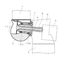
- FIG. 2 is a diagram for describing a connection mechanism between a hub and a rotary main shaft. This diagram corresponds to a region surrounded by a dotted line in FIG. 1 .
- the wind power generation system includes the blades 1 , a hub 4 , a rotary main shaft 5 , a gearbox 6 , a stationary main shaft 7 , and a frame 8 .
- the hub 4 supports the blades 1 and is rotated with the blades 1 .
- the rotary main shaft 5 is connected to the hub 4 to be rotated with the rotation of the hub 4 .
- the gearbox 6 is connected to the rotary main shaft 5 to increase the speed of the rotation.
- the stationary main shaft 7 is located at the outer diameter side of the rotary main shaft 5 with an air gap from the rotary main shaft 5 .
- the frame 8 supports the stationary main shaft 7 and is connected to the tower 3 .
- the gearbox 6 is connected to a generator, which is not shown, so that the rotating power with the rotation speed increased by the gearbox 6 drives a rotor of the generator to generate power.
- the rotary main shaft 5 is connected directly to the hub 4 on a step inside the hub 4 .
- the rotary main shaft 5 has a through hole 9 for wiring or piping for the control of an electrical device inside the hub.
- the stationary main shaft 7 which is connected to the frame 8 so as to enclose part of the rotary main shaft 5 , does not rotate.
- Two bearings 10 a and 10 b are provided between the hub 4 and the stationary main shaft 7 to support the weight of the blades 1 and the hub 4 .
- the hub 4 has an opening 11 in an axial direction of the rotary main shaft 5 at the side opposite to the gearbox 6 .
- the rotary main shaft 5 has a maximum diameter smaller than the inner diameter of the opening 11 , so that the rotary main shaft 5 can be brought into the hub 4 through the opening 11 .
- the rotary main shaft 5 has a bell-mouth shape with its inner and outer diameters expanding in the axial direction of the rotary main shaft 5 from the gearbox 6 side toward a connecting surface of the rotary main shaft 5 to the hub 4 .
- the inner and outer diameters of the rotary main shaft 5 have differences constituting its thicknesses that reduce toward the connecting surface to the hub 4 from the gearbox 6 side, except for an increase in thickness in close proximity to a portion fastened by a bolt to the hub 4 .
- This arrangement permits the rotary main shaft 5 to deform locally at the bell-mouth shaped portion, which is flexible in proximity to the connecting portion to the hub, so that misalignment can accommodated in both of the axial direction and a radial direction of the rotary main shaft 5 .
- the thicknesses described above are set to enhance this accommodating capability.
- the rotary main shaft 5 which is shaped to be shorter than those described in JP 2001-200781 A, can alleviate bending stress and vibration of the rotary main shaft, reducing the size of the frame covering the short rotary main shaft and thereby achieving weight reduction. Additionally, since the elastic coupler described in JP 2001-200781 A is not required, this arrangement eliminates the connecting work for the elastic coupler, achieves weight reduction due to the eliminated elastic coupler and its connecting components, and precludes the risk of slipping between the rotary main shaft and the elastic coupler with the connecting surface therebetween eliminated.
- the direct connection refers to connection not through an elastic coupling material, which is an individual component.
- a washer or the like used between the rotary main shaft 5 and the hub 4 for bolt fastening falls under the direct connection.
- the flexible portion in this embodiment is the bell-mouth shaped portion, which is provided as an example.
- a flexible portion in any other shape produces a similar effect.
- a rotary main shaft 5 in this embodiment is connected to a hub flange 12 , which protrudes in a hub 4 , on a surface thereof facing an opening 11 and opposite to a gearbox 6 .
- the rotary main shaft 5 has a bell mouth with its maximum diameter smaller than that of the first embodiment to reduce the opening 11 of the hub 4 and thereby reduce the weight of the hub 4 in comparison with the first embodiment. This arrangement permits the rotary main shaft 5 to deform locally at the bell-mouth shape, so that misalignment can be accommodated in both of the axial direction and the radial direction of the rotary main shaft 5 .
- a third embodiment will now be described with reference to FIG. 4 . Duplicated description of the arrangements and effects described in the second embodiment will be omitted here. While the rotary main shaft 5 in the second embodiment is connected to the hub flange 12 , which protrudes in the hub 4 , on the surface thereof facing the opening 11 and opposite to the gearbox 6 , a rotary main shaft 5 in this embodiment is connected to a hub flange 12 , which protrudes in a hub 4 , on a surface thereof facing a gearbox 6 and opposite to an opening 11 .
- the rotary main shaft 5 has a bell mouth with its maximum diameter smaller than an inner diameter (the minimum diameter) of a stationary main shaft 7 to permit the rotary main shaft 5 to be brought into the hub 4 from the side at which the stationary main shaft 7 is connected to a frame 8 .
- This arrangement minimizes the opening 11 to a size needed for maintenance access to reduce the weight of the hub 4 in comparison with the first and second embodiments.
- This arrangement permits the rotary main shaft 5 to deform locally at the bell-mouth shape, so that misalignment can be accommodated in both of the axial direction and the radial direction of the rotary main shaft 5 .
- a fourth embodiment will now be described with reference to FIG. 5 . Duplicated description of the arrangements and effects described in the first embodiment will be omitted here.
- This embodiment provides an arrangement including one bearing 13 located in a hub 4 in place of the two bearings in the first embodiment.
- a fifth embodiment will now be described with reference to FIG. 6 . Duplicated description of the arrangements and effects described in the second embodiment will be omitted here.
- This embodiment provides an arrangement including one bearing 13 located in a hub 4 in place of the two bearings in the second embodiment.
- This embodiment provides an arrangement including one bearing 13 located in a hub 4 in place of the two bearings in the third embodiment.
- the rotary main shaft 5 has a flexible portion that allows deformation.
- a flexible portion is also provided in a hub 4 to allow deformation.
- FIG. 8A An example is illustrated in FIG. 8A .
- a hub flange 14 a has a curved-surfaced structure to impart flexibility also to the hub 4 , so that the flexibility can be improved further for the entire structure.
- FIG. 8B is a diagram of a hub flange 14 b observed from the axial direction of a rotary main shaft 5 .
- an air gap 15 may be provided in the hub flange 14 b to impart flexibility also to a hub 4 .
- the flexibility can be improved further for the entire structure.
- This example can also reduce the weight of the hub 4 .
Abstract
A wind power generation system according to the invention includes: blades configured to receive wind to rotate; a nacelle supporting a load from the blades; a tower supporting the nacelle; a hub supporting the blades and configured to be rotated with the blades; a rotary main shaft configured to be rotated with the rotation of the hub; a gearbox connected to the rotary main shaft and configured to increase a speed of the rotation; and a generator configured to be driven at the rotation speed increased by the gearbox. The rotary main shaft is connected directly to the hub.
Description
1. Field of the Invention
The present invention relates to a wind power generation system.
2. Description of the Related Art
Wind power generation systems have been introduced widely as a pillar of the renewable energy technology. Wind power generation systems generate power by transmitting the rotating power of blades via the rotation of a hub, which supports the blades, to a main shaft and thereby rotating a generator.
A conventional wind power generation system is described in JP 2001-200781 A, for example. In this document, a nacelle houses a hub that supports blades and rotates with the blades, an elongated rotary main shaft that is located at the inner diameter side of the hub and is connected to the hub through an elastic coupler, a gearbox that is connected to the elongated rotary main shaft, and a generator that receives the rotating power with a speed increased by the gearbox.
In JP 2001-200781 A, the rotary main shaft can be elongated because the shaft is not subjected to bending stress due to the weight of the rotor.
In the wind power generation system described in JP 2001-200781 A, the elongated rotary main shaft is connected to the hub through the highly flexible elastic coupler, permitting the elastic coupler and the elongated rotary main shaft to achieve flexible deformation due to the rotor weight and thereby alleviating the bending stress and vibration of the rotary main shaft.
This system suffers problems, such as an increase in time for connecting work with an increase in the number of components at the connecting portion between the rotary main shaft and the elastic coupler, an increase in weight of the elastic coupler, and an increase in weight of a frame covering the elongated rotary main shaft. The system also poses a risk of slipping at the connecting surface between the rotary main shaft and the elastic coupler.
Since the connecting surface between the rotary main shaft and the elastic coupler is located at the inner circumference side of the connecting surface between the hub and the elastic coupler, the connecting surface between the rotary main shaft and the elastic coupler needs to have a holding force greater than that of the connecting surface between the hub and the elastic coupler. The connecting surface between the rotary main shaft and the elastic coupler poses a greater risk of slipping than the connecting surface between the hub and the elastic coupler, and thus it is necessary to maintain the joint at the connecting surface between the rotary main shaft and the elastic coupler with high reliability.
It is an object of the invention to provide a wind power generation system with high reliability.
To achieve the object described above, a wind power generation system according to the invention includes: blades configured to receive wind to rotate; a nacelle supporting a load from the blades; a tower supporting the nacelle; a hub supporting the blades and configured to be rotated with the blades; a rotary main shaft configured to be rotated with the rotation of the hub; a gearbox connected to the rotary main shaft and configured to increase a speed of the rotation; and a generator configured to be driven at the rotation speed increased by the gearbox, wherein the rotary main shaft is connected directly to the hub.
With this invention, a wind power generation system with high reliability can be provided.
Some embodiments of the invention will now be described with reference to the drawings. These specific embodiments are provided just as examples, and the invention is not limited thereto.
A first embodiment of the invention will now be described with reference to FIGS. 1 and 2 . In FIG. 1 , a wind power generation system includes blades 1 that receive wind to rotate, a nacelle 2 that supports a load from the blades 1, and a tower 3 that supports the nacelle 2. The nacelle 2 is supported rotatably in a substantially horizontal plane with respect to the tower 3 and is rotated in response to the wind direction.
The stationary main shaft 7, which is connected to the frame 8 so as to enclose part of the rotary main shaft 5, does not rotate. Two bearings 10 a and 10 b are provided between the hub 4 and the stationary main shaft 7 to support the weight of the blades 1 and the hub 4.
The hub 4 has an opening 11 in an axial direction of the rotary main shaft 5 at the side opposite to the gearbox 6. The rotary main shaft 5 has a maximum diameter smaller than the inner diameter of the opening 11, so that the rotary main shaft 5 can be brought into the hub 4 through the opening 11.
The rotary main shaft 5 has a bell-mouth shape with its inner and outer diameters expanding in the axial direction of the rotary main shaft 5 from the gearbox 6 side toward a connecting surface of the rotary main shaft 5 to the hub 4. The inner and outer diameters of the rotary main shaft 5 have differences constituting its thicknesses that reduce toward the connecting surface to the hub 4 from the gearbox 6 side, except for an increase in thickness in close proximity to a portion fastened by a bolt to the hub 4. This arrangement permits the rotary main shaft 5 to deform locally at the bell-mouth shaped portion, which is flexible in proximity to the connecting portion to the hub, so that misalignment can accommodated in both of the axial direction and a radial direction of the rotary main shaft 5. The thicknesses described above are set to enhance this accommodating capability.
With the bell-mouth shape accommodating misalignment, the rotary main shaft 5, which is shaped to be shorter than those described in JP 2001-200781 A, can alleviate bending stress and vibration of the rotary main shaft, reducing the size of the frame covering the short rotary main shaft and thereby achieving weight reduction. Additionally, since the elastic coupler described in JP 2001-200781 A is not required, this arrangement eliminates the connecting work for the elastic coupler, achieves weight reduction due to the eliminated elastic coupler and its connecting components, and precludes the risk of slipping between the rotary main shaft and the elastic coupler with the connecting surface therebetween eliminated.
These effects are produced by the direct connection of the rotary main shaft 5 to the hub 4. Here, the direct connection refers to connection not through an elastic coupling material, which is an individual component. For example, a washer or the like used between the rotary main shaft 5 and the hub 4 for bolt fastening falls under the direct connection.
An elastic coupling material is not required because the rotary main shaft 5 has a flexible portion that allows deformation. The flexible portion in this embodiment is the bell-mouth shaped portion, which is provided as an example. A flexible portion in any other shape produces a similar effect.
A second embodiment will now be described with reference to FIG. 3 . Duplicated description of the arrangements and effects described in the first embodiment will be omitted here. While the rotary main shaft 5 in the first embodiment is connected to the step inside the hub 4, a rotary main shaft 5 in this embodiment is connected to a hub flange 12, which protrudes in a hub 4, on a surface thereof facing an opening 11 and opposite to a gearbox 6. The rotary main shaft 5 has a bell mouth with its maximum diameter smaller than that of the first embodiment to reduce the opening 11 of the hub 4 and thereby reduce the weight of the hub 4 in comparison with the first embodiment. This arrangement permits the rotary main shaft 5 to deform locally at the bell-mouth shape, so that misalignment can be accommodated in both of the axial direction and the radial direction of the rotary main shaft 5.
A third embodiment will now be described with reference to FIG. 4 . Duplicated description of the arrangements and effects described in the second embodiment will be omitted here. While the rotary main shaft 5 in the second embodiment is connected to the hub flange 12, which protrudes in the hub 4, on the surface thereof facing the opening 11 and opposite to the gearbox 6, a rotary main shaft 5 in this embodiment is connected to a hub flange 12, which protrudes in a hub 4, on a surface thereof facing a gearbox 6 and opposite to an opening 11. The rotary main shaft 5 has a bell mouth with its maximum diameter smaller than an inner diameter (the minimum diameter) of a stationary main shaft 7 to permit the rotary main shaft 5 to be brought into the hub 4 from the side at which the stationary main shaft 7 is connected to a frame 8. This arrangement minimizes the opening 11 to a size needed for maintenance access to reduce the weight of the hub 4 in comparison with the first and second embodiments. This arrangement permits the rotary main shaft 5 to deform locally at the bell-mouth shape, so that misalignment can be accommodated in both of the axial direction and the radial direction of the rotary main shaft 5.
A fourth embodiment will now be described with reference to FIG. 5 . Duplicated description of the arrangements and effects described in the first embodiment will be omitted here. This embodiment provides an arrangement including one bearing 13 located in a hub 4 in place of the two bearings in the first embodiment.
A fifth embodiment will now be described with reference to FIG. 6 . Duplicated description of the arrangements and effects described in the second embodiment will be omitted here. This embodiment provides an arrangement including one bearing 13 located in a hub 4 in place of the two bearings in the second embodiment.
A sixth embodiment will now be described with reference to FIG. 7 . Duplicated description of the arrangements and effects described in the third embodiment will be omitted here. This embodiment provides an arrangement including one bearing 13 located in a hub 4 in place of the two bearings in the third embodiment.
A seventh embodiment will now be described with reference to FIGS. 8A and 8B . In each of the embodiments described above, the rotary main shaft 5 has a flexible portion that allows deformation. In this embodiment, a flexible portion is also provided in a hub 4 to allow deformation.
An example is illustrated in FIG. 8A . As illustrated in an enlarged view enclosed in a square in FIG. 8A , a hub flange 14 a has a curved-surfaced structure to impart flexibility also to the hub 4, so that the flexibility can be improved further for the entire structure.
Another example is illustrated in FIG. 8B . FIG. 8B is a diagram of a hub flange 14 b observed from the axial direction of a rotary main shaft 5. As illustrated in this figure, an air gap 15 may be provided in the hub flange 14 b to impart flexibility also to a hub 4. As a result, the flexibility can be improved further for the entire structure. This example can also reduce the weight of the hub 4.
Claims (12)
1. A wind power generation system, comprising:
blades configured to receive wind to rotate;
a nacelle supporting a load from the blades;
a tower supporting the nacelle;
a frame connected to the tower;
a hub housing supporting the blades and configured to be rotated with the blades;
a rotary main shaft configured to be rotated with the rotation of the hub housing;
a stationary main shaft that is connected to the frame and that encloses part of the rotary main shaft;
a gearbox connected to the rotary main shaft and configured to increase a speed of the rotation; and
a generator configured to be driven at the rotation speed increased by the gearbox, wherein
the rotary main shaft has a flexible portion that allows deformation, and
the rotary main shaft is made of a single unitary body having a first end and a second end, the first end of the rotary main shaft being cylindrical and being disposed radially inward relative to the stationary main shaft, the second end of the rotary main shaft: i) being opposite to the first end, and ii) having an outermost portion that is radially outward relative to an outermost surface of the stationary main shaft.
2. The wind power generation system according to claim 1 , wherein
the flexible portion is a bell-mouth shaped portion expanding toward a connecting portion to the hub housing.
3. The wind power generation system according to claim 2 , wherein
the rotary main shaft has a through hole, so that the rotary main shaft has inner and outer diameters with differences constituting thicknesses thereof that reduce in the bell-mouth shaped portion toward the connecting portion to the hub housing.
4. The wind power generation system according to claim 1 , wherein
the hub housing has an opening in an axial direction of the rotary main shaft at a side opposite to the gearbox, and the rotary main shaft has a maximum diameter smaller than an inner diameter of the opening.
5. The wind power generation system according to claim 1 , further comprising:
a bearing located between the hub housing and the stationary main shaft.
6. The wind power generation system according to claim 1 , wherein
the hub housing has a flexible portion that allows deformation.
7. The wind power generation system according to claim 1 , wherein the rotary main shaft has a first end at the flexible portion thereof, and a second end opposite to the first end, the second end being cylindrical and the first end having a flange shape.
8. The wind power generation system according to claim 1 , wherein the hub housing defines an interior cavity having a stepped portion, the stepped portion including an axially facing surface that directly engages with the second end of the rotary main shaft.
9. A rotary main shaft connecting a rotation body to a rotation body for a wind power generation system, wherein
the rotary main shaft comprises a flexible portion that allows deformation; and
the wind power generation system, comprises
blades configured to receive wind to rotate,
a nacelle supporting a load from the blades,
a tower supporting the nacelle,
a frame connected to the tower,
a hub housing supporting the blades and configured to be rotated with the blades,
a rotary main shaft configured to be rotated with the rotation of the hub housing,
a stationary main shaft that is connected to the frame and that encloses part of the rotary main shaft,
a gearbox connected to the rotary main shaft and configured to increase a speed of the rotation,
a generator configured to be driven at the rotation speed increased by the gearbox, the rotary main shaft being connected directly to the hub housing, wherein
the rotary main shaft is made of a single unitary body having a first end and a second end, the first end of the rotary main shaft being cylindrical and being disposed radially inward relative to the stationary main shaft, the second end of the rotary main shaft: i) being opposite to the first end, and ii) having an outermost portion that is radially outward relative to an outermost surface of the stationary main shaft.
10. The rotary main shaft according to claim 9 , wherein the rotary main shaft has a first end at the flexible portion thereof, and a second end opposite to the first end, the second end being cylindrical and the first end having a flange shape.
11. The rotary main shaft according to claim 9 , wherein the hub housing defines an interior cavity having a stepped portion, the stepped portion including an axially facing surface that directly engages with the second end of the rotary main shaft.
12. A wind power generation system, comprising:
blades configured to receive wind to rotate;
a nacelle supporting a load from the blades;
a tower supporting the nacelle;
a hub housing supporting the blades and configured to be rotated with the blades;
a rotary main shaft configured to be rotated with the rotation of the hub housing;
a gearbox connected to the rotary main shaft and configured to increase a speed of the rotation; and
a generator configured to be driven at the rotation speed increased by the gearbox, wherein
the rotary main shaft has a flexible portion that allows deformation,
the rotary main shaft is made of a single unitary body having a first end and a second end, and
the hub housing defines an interior cavity having a stepped portion, the stepped portion including an axially facing surface that directly engages with the second end of the rotary main shaft.
Applications Claiming Priority (2)
| Application Number | Priority Date | Filing Date | Title |
|---|---|---|---|
| JP2013-177480 | 2013-08-29 | ||
| JP2013177480A JP6138633B2 (en) | 2013-08-29 | 2013-08-29 | Wind power generation system |
Publications (2)
| Publication Number | Publication Date |
|---|---|
| US20150064007A1 US20150064007A1 (en) | 2015-03-05 |
| US10125742B2 true US10125742B2 (en) | 2018-11-13 |
Family
ID=51260765
Family Applications (1)
| Application Number | Title | Priority Date | Filing Date |
|---|---|---|---|
| US14/448,536 Active 2035-10-22 US10125742B2 (en) | 2013-08-29 | 2014-07-31 | Wind power generation system |
Country Status (6)
| Country | Link |
|---|---|
| US (1) | US10125742B2 (en) |
| EP (1) | EP2843229B1 (en) |
| JP (1) | JP6138633B2 (en) |
| CN (1) | CN104421098A (en) |
| CA (1) | CA2856393A1 (en) |
| TW (1) | TWI557316B (en) |
Families Citing this family (3)
| Publication number | Priority date | Publication date | Assignee | Title |
|---|---|---|---|---|
| DE102017114584A1 (en) * | 2017-06-29 | 2019-01-03 | Wobben Properties Gmbh | Wind turbine rotary joint, and wind turbine with selbiger |
| US11073137B2 (en) | 2019-07-02 | 2021-07-27 | General Electric Company | Journal bearing housing and shaft for a wind turbine drivetrain having corresponding deformation |
| CN111852787A (en) * | 2020-07-29 | 2020-10-30 | 上海电气风电集团股份有限公司 | Driving chain structure of wind generating set and wind driven generator comprising same |
Citations (10)
| Publication number | Priority date | Publication date | Assignee | Title |
|---|---|---|---|---|
| JPS62282173A (en) | 1986-05-31 | 1987-12-08 | Yamaha Motor Co Ltd | Rotor supporting structure for propeller type wind mill |
| US4757211A (en) * | 1987-07-10 | 1988-07-12 | Danregn Vidraft A/S | Machine for generating electricity |
| JP2001200781A (en) | 1999-11-29 | 2001-07-27 | Ecotecnia Soc Coop Catalana Ltda | Wind power generator |
| US20090015020A1 (en) | 2007-07-10 | 2009-01-15 | Siemens Aktiengesellschaft | Wind turbine, method for mounting a wind turbine and method for adjusting an air gap between a rotor and a stator of a generator of a wind turbine |
| JP2009138578A (en) | 2007-12-05 | 2009-06-25 | E & E Kk | Rotor supporting structure of horizontal axis wind turbine |
| WO2012052022A1 (en) | 2010-10-18 | 2012-04-26 | Vestas Wind Systems A/S | Wind turbine power transmission system |
| US20130011262A1 (en) | 2010-06-04 | 2013-01-10 | Zhejiang Huaying Waind Power Generator Co., Ltd. | Downwind Variable Pitch Wind Turbine Generator |
| WO2013021181A1 (en) | 2011-08-05 | 2013-02-14 | David Brown Gear Systems Limited | A drive arrangement for a wind turbine |
| US8664791B2 (en) * | 2010-06-21 | 2014-03-04 | Envision Energy (Denmark) Aps | Flexible shaft wind turbine |
| US20140064963A1 (en) * | 2012-09-06 | 2014-03-06 | Hitachi, Ltd. | Wind Turbine System, an Assembling Method of a Wind Turbine System, an Inspecting Method of a Wind Turbine System, and an Operation Method of a Wind Turbine System |
Family Cites Families (4)
| Publication number | Priority date | Publication date | Assignee | Title |
|---|---|---|---|---|
| BE1017135A3 (en) * | 2006-05-11 | 2008-03-04 | Hansen Transmissions Int | A GEARBOX FOR A WIND TURBINE. |
| CN201103511Y (en) * | 2007-11-15 | 2008-08-20 | 陈亦栋 | Variable oar wind wheel |
| CN201963465U (en) * | 2010-12-09 | 2011-09-07 | 厦门蓝溪科技有限公司 | Main shaft structure of double large-sized direct driven wind driven generators |
| KR20130059309A (en) * | 2011-09-22 | 2013-06-05 | 미츠비시 쥬고교 가부시키가이샤 | Renewable energy type generating apparatus, and mounting and demounting method of a rotary blade thereof |
-
2013
- 2013-08-29 JP JP2013177480A patent/JP6138633B2/en active Active
-
2014
- 2014-07-07 TW TW103123313A patent/TWI557316B/en active
- 2014-07-10 CA CA2856393A patent/CA2856393A1/en not_active Abandoned
- 2014-07-31 US US14/448,536 patent/US10125742B2/en active Active
- 2014-08-04 EP EP14179697.9A patent/EP2843229B1/en not_active Not-in-force
- 2014-08-04 CN CN201410379773.5A patent/CN104421098A/en active Pending
Patent Citations (11)
| Publication number | Priority date | Publication date | Assignee | Title |
|---|---|---|---|---|
| JPS62282173A (en) | 1986-05-31 | 1987-12-08 | Yamaha Motor Co Ltd | Rotor supporting structure for propeller type wind mill |
| US4757211A (en) * | 1987-07-10 | 1988-07-12 | Danregn Vidraft A/S | Machine for generating electricity |
| JP2001200781A (en) | 1999-11-29 | 2001-07-27 | Ecotecnia Soc Coop Catalana Ltda | Wind power generator |
| US20090015020A1 (en) | 2007-07-10 | 2009-01-15 | Siemens Aktiengesellschaft | Wind turbine, method for mounting a wind turbine and method for adjusting an air gap between a rotor and a stator of a generator of a wind turbine |
| JP2009138578A (en) | 2007-12-05 | 2009-06-25 | E & E Kk | Rotor supporting structure of horizontal axis wind turbine |
| US20130011262A1 (en) | 2010-06-04 | 2013-01-10 | Zhejiang Huaying Waind Power Generator Co., Ltd. | Downwind Variable Pitch Wind Turbine Generator |
| US8664791B2 (en) * | 2010-06-21 | 2014-03-04 | Envision Energy (Denmark) Aps | Flexible shaft wind turbine |
| WO2012052022A1 (en) | 2010-10-18 | 2012-04-26 | Vestas Wind Systems A/S | Wind turbine power transmission system |
| US20130302144A1 (en) * | 2010-10-18 | 2013-11-14 | Vestas Wind Systems A/S | Wind turbine power transmission system |
| WO2013021181A1 (en) | 2011-08-05 | 2013-02-14 | David Brown Gear Systems Limited | A drive arrangement for a wind turbine |
| US20140064963A1 (en) * | 2012-09-06 | 2014-03-06 | Hitachi, Ltd. | Wind Turbine System, an Assembling Method of a Wind Turbine System, an Inspecting Method of a Wind Turbine System, and an Operation Method of a Wind Turbine System |
Non-Patent Citations (1)
| Title |
|---|
| English translation of Japanese Office Action issued in counterpart Japanese Application No. 2013-177480 dated Sep. 27, 2016 (three pages). |
Also Published As
| Publication number | Publication date |
|---|---|
| JP6138633B2 (en) | 2017-05-31 |
| TW201525274A (en) | 2015-07-01 |
| JP2015045292A (en) | 2015-03-12 |
| CN104421098A (en) | 2015-03-18 |
| US20150064007A1 (en) | 2015-03-05 |
| EP2843229B1 (en) | 2016-01-20 |
| CA2856393A1 (en) | 2015-02-28 |
| TWI557316B (en) | 2016-11-11 |
| EP2843229A1 (en) | 2015-03-04 |
Similar Documents
| Publication | Publication Date | Title |
|---|---|---|
| US10316826B2 (en) | Drive system of a wind turbine | |
| EP2500564B1 (en) | Gear box, seal and cover arrangements | |
| US20060152014A1 (en) | Method and apparatus for wind turbine air gap control | |
| US8033951B2 (en) | Gearbox for a wind turbine | |
| US20110143880A1 (en) | Drivetrain for generator in wind turbine | |
| US10125742B2 (en) | Wind power generation system | |
| KR20100021558A (en) | Wind power generator | |
| US10502196B2 (en) | Slip ring system for a wind turbine wind turbine and a method for producing electrical energy | |
| KR101799354B1 (en) | Wind power generator and wind power generater system | |
| CN108757351B (en) | Direct-drive wind generating set | |
| AU2013349341B2 (en) | Machine with two co-axial rotors | |
| US8647224B2 (en) | Generator arrangement for a wind power plant | |
| US9243614B2 (en) | Wind powered apparatus having counter rotating blades | |
| CN110318959A (en) | Machine rack for wind power plant | |
| US9074579B2 (en) | Power generator | |
| US20120274074A1 (en) | Continuous-Flow Power Installation | |
| EP2935881A1 (en) | Flexible driving shaft | |
| US11525477B2 (en) | Fractal structure for power-generation of bearing rotating vibration | |
| JP2020133511A (en) | Rotary electric machine, power generator and wind power generation facility | |
| CN105221340A (en) | A kind of structure-improved of compact type wind power generating set | |
| US20220389911A1 (en) | Wind turbine power transmission system | |
| JP2014051903A (en) | Wind power generating system, method of assembling wind power generating system, and method of inspecting wind power generating system | |
| WO2011089036A1 (en) | Planetary gear unit with rotating ring gear | |
| JP2015227651A (en) | Wind power generator | |
| JP6272147B2 (en) | Wind power generator |
Legal Events
| Date | Code | Title | Description |
|---|---|---|---|
| AS | Assignment |
Owner name: HITACHI, LTD., JAPAN Free format text: ASSIGNMENT OF ASSIGNORS INTEREST;ASSIGNORS:TANAKA, KOHEI;TOBINAGA, IKUO;SAEKI, MITSURU;REEL/FRAME:033441/0010 Effective date: 20140708 |
|
| STCF | Information on status: patent grant |
Free format text: PATENTED CASE |
|
| MAFP | Maintenance fee payment |
Free format text: PAYMENT OF MAINTENANCE FEE, 4TH YEAR, LARGE ENTITY (ORIGINAL EVENT CODE: M1551); ENTITY STATUS OF PATENT OWNER: LARGE ENTITY Year of fee payment: 4 |