US10107472B2 - Luminaire with slot-mounted LED module - Google Patents
Luminaire with slot-mounted LED module Download PDFInfo
- Publication number
- US10107472B2 US10107472B2 US15/143,056 US201615143056A US10107472B2 US 10107472 B2 US10107472 B2 US 10107472B2 US 201615143056 A US201615143056 A US 201615143056A US 10107472 B2 US10107472 B2 US 10107472B2
- Authority
- US
- United States
- Prior art keywords
- light engine
- assembly
- luminaire
- engine assembly
- aperture
- Prior art date
- Legal status (The legal status is an assumption and is not a legal conclusion. Google has not performed a legal analysis and makes no representation as to the accuracy of the status listed.)
- Expired - Fee Related, expires
Links
Images


Classifications
-
- F—MECHANICAL ENGINEERING; LIGHTING; HEATING; WEAPONS; BLASTING
- F21—LIGHTING
- F21V—FUNCTIONAL FEATURES OR DETAILS OF LIGHTING DEVICES OR SYSTEMS THEREOF; STRUCTURAL COMBINATIONS OF LIGHTING DEVICES WITH OTHER ARTICLES, NOT OTHERWISE PROVIDED FOR
- F21V3/00—Globes; Bowls; Cover glasses
-
- F—MECHANICAL ENGINEERING; LIGHTING; HEATING; WEAPONS; BLASTING
- F21—LIGHTING
- F21V—FUNCTIONAL FEATURES OR DETAILS OF LIGHTING DEVICES OR SYSTEMS THEREOF; STRUCTURAL COMBINATIONS OF LIGHTING DEVICES WITH OTHER ARTICLES, NOT OTHERWISE PROVIDED FOR
- F21V17/00—Fastening of component parts of lighting devices, e.g. shades, globes, refractors, reflectors, filters, screens, grids or protective cages
- F21V17/002—Fastening of component parts of lighting devices, e.g. shades, globes, refractors, reflectors, filters, screens, grids or protective cages with provision for interchangeability, i.e. component parts being especially adapted to be replaced by another part with the same or a different function
-
- F—MECHANICAL ENGINEERING; LIGHTING; HEATING; WEAPONS; BLASTING
- F21—LIGHTING
- F21V—FUNCTIONAL FEATURES OR DETAILS OF LIGHTING DEVICES OR SYSTEMS THEREOF; STRUCTURAL COMBINATIONS OF LIGHTING DEVICES WITH OTHER ARTICLES, NOT OTHERWISE PROVIDED FOR
- F21V17/00—Fastening of component parts of lighting devices, e.g. shades, globes, refractors, reflectors, filters, screens, grids or protective cages
- F21V17/10—Fastening of component parts of lighting devices, e.g. shades, globes, refractors, reflectors, filters, screens, grids or protective cages characterised by specific fastening means or way of fastening
- F21V17/12—Fastening of component parts of lighting devices, e.g. shades, globes, refractors, reflectors, filters, screens, grids or protective cages characterised by specific fastening means or way of fastening by screwing
-
- F—MECHANICAL ENGINEERING; LIGHTING; HEATING; WEAPONS; BLASTING
- F21—LIGHTING
- F21V—FUNCTIONAL FEATURES OR DETAILS OF LIGHTING DEVICES OR SYSTEMS THEREOF; STRUCTURAL COMBINATIONS OF LIGHTING DEVICES WITH OTHER ARTICLES, NOT OTHERWISE PROVIDED FOR
- F21V23/00—Arrangement of electric circuit elements in or on lighting devices
- F21V23/001—Arrangement of electric circuit elements in or on lighting devices the elements being electrical wires or cables
-
- F—MECHANICAL ENGINEERING; LIGHTING; HEATING; WEAPONS; BLASTING
- F21—LIGHTING
- F21V—FUNCTIONAL FEATURES OR DETAILS OF LIGHTING DEVICES OR SYSTEMS THEREOF; STRUCTURAL COMBINATIONS OF LIGHTING DEVICES WITH OTHER ARTICLES, NOT OTHERWISE PROVIDED FOR
- F21V29/00—Protecting lighting devices from thermal damage; Cooling or heating arrangements specially adapted for lighting devices or systems
- F21V29/50—Cooling arrangements
- F21V29/70—Cooling arrangements characterised by passive heat-dissipating elements, e.g. heat-sinks
- F21V29/74—Cooling arrangements characterised by passive heat-dissipating elements, e.g. heat-sinks with fins or blades
- F21V29/75—Cooling arrangements characterised by passive heat-dissipating elements, e.g. heat-sinks with fins or blades with fins or blades having different shapes, thicknesses or spacing
-
- F—MECHANICAL ENGINEERING; LIGHTING; HEATING; WEAPONS; BLASTING
- F21—LIGHTING
- F21V—FUNCTIONAL FEATURES OR DETAILS OF LIGHTING DEVICES OR SYSTEMS THEREOF; STRUCTURAL COMBINATIONS OF LIGHTING DEVICES WITH OTHER ARTICLES, NOT OTHERWISE PROVIDED FOR
- F21V5/00—Refractors for light sources
- F21V5/04—Refractors for light sources of lens shape
-
- F—MECHANICAL ENGINEERING; LIGHTING; HEATING; WEAPONS; BLASTING
- F21—LIGHTING
- F21K—NON-ELECTRIC LIGHT SOURCES USING LUMINESCENCE; LIGHT SOURCES USING ELECTROCHEMILUMINESCENCE; LIGHT SOURCES USING CHARGES OF COMBUSTIBLE MATERIAL; LIGHT SOURCES USING SEMICONDUCTOR DEVICES AS LIGHT-GENERATING ELEMENTS; LIGHT SOURCES NOT OTHERWISE PROVIDED FOR
- F21K9/00—Light sources using semiconductor devices as light-generating elements, e.g. using light-emitting diodes [LED] or lasers
- F21K9/60—Optical arrangements integrated in the light source, e.g. for improving the colour rendering index or the light extraction
- F21K9/66—Details of globes or covers forming part of the light source
-
- F—MECHANICAL ENGINEERING; LIGHTING; HEATING; WEAPONS; BLASTING
- F21—LIGHTING
- F21K—NON-ELECTRIC LIGHT SOURCES USING LUMINESCENCE; LIGHT SOURCES USING ELECTROCHEMILUMINESCENCE; LIGHT SOURCES USING CHARGES OF COMBUSTIBLE MATERIAL; LIGHT SOURCES USING SEMICONDUCTOR DEVICES AS LIGHT-GENERATING ELEMENTS; LIGHT SOURCES NOT OTHERWISE PROVIDED FOR
- F21K9/00—Light sources using semiconductor devices as light-generating elements, e.g. using light-emitting diodes [LED] or lasers
- F21K9/60—Optical arrangements integrated in the light source, e.g. for improving the colour rendering index or the light extraction
- F21K9/68—Details of reflectors forming part of the light source
-
- F—MECHANICAL ENGINEERING; LIGHTING; HEATING; WEAPONS; BLASTING
- F21—LIGHTING
- F21S—NON-PORTABLE LIGHTING DEVICES; SYSTEMS THEREOF; VEHICLE LIGHTING DEVICES SPECIALLY ADAPTED FOR VEHICLE EXTERIORS
- F21S8/00—Lighting devices intended for fixed installation
- F21S8/02—Lighting devices intended for fixed installation of recess-mounted type, e.g. downlighters
- F21S8/026—Lighting devices intended for fixed installation of recess-mounted type, e.g. downlighters intended to be recessed in a ceiling or like overhead structure, e.g. suspended ceiling
-
- F—MECHANICAL ENGINEERING; LIGHTING; HEATING; WEAPONS; BLASTING
- F21—LIGHTING
- F21V—FUNCTIONAL FEATURES OR DETAILS OF LIGHTING DEVICES OR SYSTEMS THEREOF; STRUCTURAL COMBINATIONS OF LIGHTING DEVICES WITH OTHER ARTICLES, NOT OTHERWISE PROVIDED FOR
- F21V7/00—Reflectors for light sources
- F21V7/04—Optical design
- F21V7/06—Optical design with parabolic curvature
-
- F—MECHANICAL ENGINEERING; LIGHTING; HEATING; WEAPONS; BLASTING
- F21—LIGHTING
- F21Y—INDEXING SCHEME ASSOCIATED WITH SUBCLASSES F21K, F21L, F21S and F21V, RELATING TO THE FORM OR THE KIND OF THE LIGHT SOURCES OR OF THE COLOUR OF THE LIGHT EMITTED
- F21Y2105/00—Planar light sources
- F21Y2105/10—Planar light sources comprising a two-dimensional [2D] array of point-like light-generating elements
-
- F—MECHANICAL ENGINEERING; LIGHTING; HEATING; WEAPONS; BLASTING
- F21—LIGHTING
- F21Y—INDEXING SCHEME ASSOCIATED WITH SUBCLASSES F21K, F21L, F21S and F21V, RELATING TO THE FORM OR THE KIND OF THE LIGHT SOURCES OR OF THE COLOUR OF THE LIGHT EMITTED
- F21Y2115/00—Light-generating elements of semiconductor light sources
- F21Y2115/10—Light-emitting diodes [LED]
Definitions
- a luminaire may comprise elements configured to accommodate a specific circuit board or LED module design.
- a light engine assembly or an optical assembly may be designed to accommodate a specific size of circuit board or LED module containing a specific configuration of one or more light sources. Accordingly, each of a plurality of different luminaire circuit boards or modules may be associated with a single light engine design.
- a luminaire may include a light engine assembly, a reflector assembly slidably engaged with the light engine assembly, and an LED module.
- the light engine may include: a plurality of fins, integrally-formed with, and extending from, a block structure; a cavity extending in a first direction from the block structure creating an aperture; a slot, extending through a sidewall of the block structure into the cavity in a second direction, perpendicular to the first direction, the slot comprising a mounting surface having a surface area equal to or larger than an area of the aperture.
- the LED module may be removably-coupled to the mounting surface.
- the LED module may comprise at least one light source configured to emit light through the aperture. Further, the LED module may be removable from the cavity and slidable through the slot.
- a luminaire may comprise a light engine assembly.
- the light engine assembly may include a block structure including a heat sink; a plurality of fins integrally-formed with, and extending from the block structure; a cavity extending in a first direction from an aperture in a bottom surface of the block structure; a slot extending through a sidewall of the block structure into the cavity in a second direction, perpendicular to the first direction, the slot comprising a mounting surface having a surface area larger than an area of the aperture; and an LED module, removably-coupled to the mounting surface, comprising at least one light source configured to emit light through the aperture.
- the luminaire may comprise a reflector assembly slidably engaged with the block structure and a cover plate removably-coupled between a lower surface of the block structure and an upper flange of the reflector assembly.
- the cover plate may be removably-coupled to the light engine with one or more fasteners that provide a standoff distance between a surface of the cover plate and a flange of the one or more fasteners and the standoff distance allows the reflector assembly to slidably engage with the block structure.
- the upper flange of the reflector assembly may slidably engage with the light engine assembly such that the flange of the reflector assembly is sandwiched between the flange of the one or more fasteners and the cover plate.
- a light engine assembly for a luminaire may comprise: a block structure; a plurality of fins integrally-formed with, and extending from the block structure; a cavity extending in a first direction from an aperture in a bottom surface of the block structure; and a slot extending through a sidewall of the block structure into the cavity in a second direction, perpendicular to the first direction, the slot comprising a mounting surface having a surface area larger than an area of the aperture.
- the light engine assembly may include a cover structure removably-coupled to the light engine assembly to cover the slot.
- the mounting surface of the light engine may be configured to be removably-coupled to an LED module.
- the LED module may comprise at least one light source configured to emit light through the aperture. Further, the LED module may be removable from the cavity and slidable through the slot.
- FIG. 1 depicts an isometric view of an example luminaire, according to one or more aspects described herein.
- FIG. 2A depicts a front view of the example luminaire of FIG. 1 , according to one or more aspects described herein.
- FIG. 2B depicts a side view of the example luminaire of FIG. 1 , according to one or more aspects described herein.
- FIG. 3 depicts an isometric view of an optical assembly of the luminaire of FIG. 1 , according to one or more aspects described herein.
- FIG. 4A depicts an exploded isometric view of a light engine assembly of the optical assembly of FIG. 3 , according to one or more aspects described herein.
- FIG. 4B depicts an isometric view of the bottom of the light engine assembly of the optical assembly of FIG. 3 , according to one or more aspects described herein.
- FIG. 4C depicts an isometric view of the bottom of another embodiment of the light engine assembly of the optical assembly of FIG. 3 , according to one or more aspects described herein.
- FIG. 4D depicts a close-up side section view of the light engine assembly of FIG. 3 , according to one or more aspects described herein.
- FIG. 5 depicts an isometric view of the top of the light engine assembly of FIG. 3 , according to one or more aspects described herein.
- FIG. 6 depicts another isometric view of a bottom of the light engine assembly of FIG. 3 , according to one or more aspects described herein.
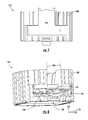
- FIG. 7 depicts an end view of the light engine assembly of FIG. 3 , according to one or more aspects described herein.
- FIG. 8 depicts another end view of the light engine assembly of FIG. 3 according to one or more aspects described herein.
- FIG. 9 depicts another view of a bottom of the light engine assembly of FIG. 3 , according to one or more aspects described herein.
- FIG. 10 depicts an isometric view of a cover structure, according to one or more aspects described herein.
- FIG. 11 depicts an elevation view of the optical assembly of FIG. 1 , according to one or more aspects described herein.
- FIGS. 12A-12C depict different views of an example round or circular reflector assembly from the optical assembly of FIG. 11 , according to one or more aspects described herein.
- FIG. 13 depicts an elevation view of another example optical assembly, according to one or more aspects described herein.
- FIGS. 14A-14C depict different views of a square or rectangular reflector assembly from the optical assembly of FIG. 13 , according to one or more aspects described herein.
- FIG. 15 depicts a bottom view of the example optical assembly of FIG. 13 , according to one or more aspects described herein.
- FIG. 16 depicts an elevation view of another example optical assembly, according to one or more aspects described herein.
- FIGS. 17A-17C depict different views of a square or rectangular wall-wash reflector assembly from the optical assembly of FIG. 13 , according to one or more aspects described herein.
- FIG. 18 depicts a bottom view of the example optical assembly of FIG. 16 , according to one or more aspects described herein.
- FIG. 19 depicts a bottom view of another example optical assembly with a circular wall-wash reflector assembly, according to one or more aspects described herein.
- aspects of this disclosure relate to a luminaire having a light engine assembly configured to be removably-coupled to a circuit board or LED module. Further, the light engine assembly, that includes a heat sink, may be configured to accommodate circuit boards or LED modules having different shapes and geometries.
- FIG. 1 depicts an isometric view of an example luminaire 100 , according to one or more aspects described herein.
- FIGS. 2A and 2B depict different views of the example luminaire 100 , according to one or more aspects described herein.
- FIG. 2A depicts a front view
- FIG. 2B depicts a side view of the luminaire 100 .
- the luminaire 100 may comprise a mounting frame assembly 102 and an aperture plate 106 that is coupled to the mounting frame assembly 102 .
- a reflector assembly 110 may be slidably engaged with, and removably-coupled to, a light engine assembly 112 .
- the light engine assembly 112 may be coupled to the aperture plate 106 and/or the mounting frame assembly 102 in any variety of ways without departing from this invention.
- the light engine assembly 112 may not utilize or be coupled with any aperture plate 106 or mounting frame assembly 102 and may be utilized as an individual and/or separate part and light engine.
- the light engine assembly 112 may include a heat sink 170 to provide a surface area from which heat energy generated by one or more light sources within the luminaire 100 may be dissipated.
- the light engine assembly 112 may include a circuit board or module 124 which may comprise one or more light sources.
- light source 148 represents one such light source.
- light source 148 may be a light-emitting diode.
- light source 148 may comprise a different light source technology, including one or more incandescent, or fluorescent light source technologies.
- the circuit board or module 124 may comprise a plurality of light sources, similar to light source 148 .
- luminaire 100 may be implemented with any number of light sources 148 , without departing from the scope of these disclosures.
- a light source 148 may have any power rating, luminous efficacy, or color temperature, without departing from the scope of these disclosures.
- circuit board or LED module 124 may comprise electronic components in addition to the one or more light sources 148 , without departing from the scope of these disclosures.
- the circuit board or LED module 124 may comprise one or more voltage regulation chips, resistors, capacitors, conduction pathways, sensors, or electrical connections, among others.
- the luminaire 100 may comprise a reflective chamber 150 positioned between reflector assembly 110 and the circuit board or LED module 124 .
- the reflective chamber 150 may comprise one or more apertures 152 .
- the aperture 142 (as illustrated in FIG. 12C ) of the reflector assembly 110 , an aperture 143 (as illustrated in FIG. 1 ) of the aperture plate 106 , and the aperture 152 of the reflective chamber 150 may be concentric with one another, and aligned along direction 120 .
- the reflective chamber 150 may include reflective surfaces.
- FIG. 4A illustrates an exploded bottom view of the light engine assembly 112 in accordance with aspects of this invention.
- the light engine assembly 112 may include a circuit board or LED module 124 located within a heat sink 170 .
- a reflective chamber 150 may be located over the circuit board or LED module 124 .
- the reflective chamber 150 may include one or more apertures 153 that may align with the location of the LEDs or light sources 148 on the circuit board or LED module 124 . Additionally, the edges of the reflective chamber 150 may be positioned within a ledge 171 of the heat sink 170 .
- a lens or diffuser plate 159 may be located above the reflective chamber 150 . As illustrated in FIG.
- the edges of the lens or diffuser plate 159 may be positioned within the ledge 171 on the heat sink 170 .
- the lens or diffuser plate 159 may be configured to, among others: focus, scatter, diffuse, or alter a color temperature or hue of light emitted from one or more light sources 148 . Additionally, there may be a notch in one of the corners or sides of the ledge 171 to correctly position and align with a notch on the reflective chamber 150 and the lens or diffuser plate 159 . In an example embodiment, as illustrated in FIG.
- a lens cover 158 may also be included in addition to the lens or diffuser plate 159 to provide additional focusing, scattering, diffusing, or altering a color temperature or hue of light emitted from one or more light sources 148 .
- a cover plate 161 may be located over the lens cover 158 , lens or diffuser plate 159 , and the reflective chamber 150 . The cover plate 161 may be utilized to secure the lens cover 158 , the lens or diffuser plate 159 , and reflective chamber 150 to the heat sink 170 and the light engine assembly 112 . The cover plate 161 may fit over the holes for securing one or more of the fasteners 154 a - 154 c to the heat sink 170 . As illustrated in FIG.
- the cover plate 161 may have an outer edge which aligns with the edges of the heat sink 170 .
- the cover plate 161 may also include an aperture 166 that aligns with the lens cover 158 , the lens or diffuser plate 159 , and the reflective chamber 150 .
- FIG. 4B depicts an isometric view of a bottom of the light engine assembly 112 .
- Fasteners 154 a - 154 c may be configured to couple the cover plate 161 (and/or lens or diffuser plate 159 ) to the light engine assembly 112 .
- fasteners 154 a - 154 c may comprise thumbscrews.
- fasteners 154 a - 154 c may comprise screws, bolts, rivets, or any other fastening structure.
- FIG. 4B depicts an isometric view of a bottom of the light engine assembly 112 .
- Fasteners 154 a - 154 c may be configured to couple the cover plate 161 (and/or lens or diffuser plate 159 ) to the light engine assembly 112 .
- fasteners 154 a - 154 c may comprise thumbscrews.
- fasteners 154 a - 154 c may comprise screws, bolts, rivets, or any other fastening
- the standoff distance 160 may allow the reflector assembly 110 to slidably engage with the light engine assembly 112 .
- an upper flange 164 of the reflector assembly 110 may slidably engage with the light engine assembly 112 , and slide along direction 118 such that the upper flange 164 of the reflector assembly 110 is sandwiched between the fasteners 154 a - 154 c and the cover plate 161 .
- the light engine assembly 112 may comprise a leaf spring 156 that is configured to compress along direction 120 as the upper flange 164 of the reflector assembly 110 slidably engages with the light engine assembly 112 along direction 118 , and to expand to that position depicted in FIGS. 4A and 4B once the reflector assembly 110 is fully engaged with the light engine assembly 112 .
- FIG. 4C depicts an isometric view of a bottom of the light engine assembly 112 .
- the light engine assembly 112 as illustrated in FIG. 4C comprises a manual slide closure 156 b that is configured to slide between a first position and a second position. In the first position, the manual slide closure 156 b is flush with the bottom of the light engine assembly 112 , such that the upper flange 164 of the reflector assembly 110 slidably engages with the light engine assembly 112 along direction 118 .
- the manual slide closure 156 b may be rotated to a second position, such that the reflector assembly 110 is locked into position on the light engine assembly 112 and held in place by the manual slide closure 156 b.
- the cover plate 161 may comprise an aperture 166 . Accordingly, aperture 166 may be embodied with any shape and/or dimensions, without departing from the scope of these disclosures.
- the aperture 166 of the cover plate 161 may have a round or square shape.
- the cover plate 161 is used to retain the lens cover 158 , the lens or diffuser plate 159 , and/or the reflective chamber 150 within the ledge 171 of the heat sink 170 .
- FIGS. 3 and 5 depict isometric views of a top of the light engine assembly 112 .
- the light engine assembly 112 may comprise a block structure 168 .
- the block structure 168 may include a heat sink 170 and be integrally-formed with a plurality of fins.
- example fins 170 a - 170 c represent three of a plurality of fins extending from the block structure 168 .
- fins 170 a - 170 c may be utilized to provide an increased surface area from which heat energy may be dissipated.
- a rate of heat energy transfer is linearly proportional to a surface area of an object that is being cooled (i.e.
- light engine assembly 112 may utilize a plurality of fins extending from a perimeter of the block structure 168 .
- the plurality of fins e.g. example fins 170 a - 170 c
- the plurality of fins may extend in a plane parallel to a plane defined by directions 118 and 122 .
- the plurality of fins e.g.
- fins 170 a - 170 c ) of light engine assembly 112 may have an approximately circular outer boundary (when viewed from a top view as in FIG. 3 ), concentric with, and extending to a diameter less than, the aperture 143 .
- the plurality of fins 170 a - 170 c of the light engine assembly 112 may include two opposing flat sides which allow clearance for the means of removably attaching the light engine assembly 112 to the mounting frame 102 .
- a fin from the plurality of fins that make up the light engine assembly 112 may have a curved geometry in order to increase surface area (see, e.g., curved geometry of fin 170 a from FIG. 3 ).
- the light engine assembly 112 including the block structure 168 integrally-formed with a plurality of fins ( 170 a - 170 c ) may comprise aluminum/an aluminum alloy (e.g. aluminum alloy 6061, 6063, or 1050A, among others), plastic, or copper/a copper alloy, among others.
- the light engine assembly 112 including the block structure 168 integrally-formed with a plurality of fins ( 170 a - 170 c ) may be cast, or molded (e.g. injection molding of a metal), among others. Additional or alternative machining/forming operations may be utilized to form the structure of the light engine assembly 112 , without departing from the scope of these disclosures.
- a cover structure 172 may be removably-coupled to the light engine assembly 112 at holes 174 a and 174 b by fasteners (e.g. screws, bolts, rivets, among others). Accordingly, the cover structure 172 may be removed to access a slot 184 in the block structure 168 of the light engine assembly 112 (described in further detail in relation to FIG. 8 ).
- FIG. 6 depicts an isometric view of a bottom of the light engine assembly 112 .
- light engine assembly 112 is depicted without the cover plate 161 and reflective chamber 150 of FIG. 4A .
- the light engine assembly 112 has an aperture with a width 176 and a length 178 .
- the aperture of the light engine assembly 112 has an approximately square geometry, and such that width 176 is approximately equal to length 178 .
- the light engine assembly 112 may have a cavity 180 extending from the aperture (aperture associated with width 176 and length 178 ) along direction 120 .
- the mounting points 182 a - 182 c may be utilized to removably-couple the circuit board or LED module 124 to the light engine assembly 112 .
- a surface area of the circuit board or LED module 124 may be approximately equal to an area of the aperture of the light engine assembly 112 (i.e. that area given by width 176 *length 178 ).
- the light engine assembly 112 may be configured to accommodate circuit boards or LED modules (comprising one or more light sources) with a surface area smaller than the area of the aperture of the light engine assembly 112 (i.e. that area given by width 176 *length 178 ), or greater than the area of the aperture of the light engine assembly 112 (i.e.
- light engine assembly 112 may be utilized with different light source circuits accommodated on different circuit board or LED module sizes, as offered by one or more different manufacturers.
- one or more of the mounting points 182 a - 182 c (as well as additional mounting points on the light engine assembly 112 , but not utilized by the circuit board or LED module 124 ) may be associated with one or more mounting point patterns that are common to, or compatible with the circuit board or LED module 124 , as well as alternative circuit boards or LED modules that may be positioned within the light engine assembly 112 .
- FIG. 7 depicts an end view of the light engine assembly 112 .
- FIG. 7 depicts the cover structure 172 coupled to the light engine assembly 112 .
- FIG. 8 depicts the light engine assembly 112 with the cover structure 172 removed, and such that a slot 184 in a side of the light engine assembly 112 is exposed.
- the slot 184 may extend approximately along direction 118 through a sidewall of the block structure 168 into the cavity 180 .
- the light engine assembly 112 may have a gap 186 in the fins of the heat sink 170 in order to accommodate electrical cabling extending from the circuit board or LED module 124 to the junction box 114 .
- the cover structure 172 may be positioned within the gap 186 .
- FIG. 9 depicts a view of the bottom of the light engine assembly 112 .
- light engine assembly 112 may be referred to as a slot-loading light engine assembly 112 since a circuit board or LED module, such as circuit board or LED module 124 , may be positioned within the cavity 180 by being loaded through the slot 184 .
- FIG. 9 depicts the light engine assembly 112 without the circuit board or LED module 124 .
- a width of the slot 184 may be approximately equal to length 178 associated with the aperture of the cavity 180 . In another example, a width of the slot 184 may be less than, or more than length 178 .
- element 187 represents a mounting surface onto which the circuit board or LED module 124 , or an alternative implementation of a circuit board or LED module compatible with the light engine assembly 112 , may be mounted.
- the mounting surface 187 may have a surface area that is larger than the area of the aperture of the light engine assembly 112 (i.e. that area given by width 176 *length 178 ).
- Surface 188 of the light engine assembly 112 may be referred to as a bottom surface of the light engine assembly 112 , and may be removably-coupled to the cover plate 161 by fasteners 154 a - 154 c that are received into holes 190 a - 190 c (e.g. threaded holes 190 a - 190 c ).
- FIG. 10 depicts an isometric view of the cover structure 172 .
- the cover structure 172 may have a plate 192 configured to be received into the gap 186 in the fins of the block structure 168 of the light engine assembly 112 as well as the slot 184 . Additionally, the cover structure 172 may comprise a wire port 194 having a cylindrical bore 196 through which one or more electrical wires may extend between the circuit board or LED module 124 and the junction box 114 .
- the cover structure 172 may comprise one or more aluminum alloys or copper alloys, among others. In another example, the cover structure 172 may comprise one or more polymer materials, among others.
- the cover structure 172 may be sized and shaped to accommodate other circuit board or LED module 124 geometries where the circuit board or LED module 124 and wires associated with the circuit board or LED module 124 are connected along various portions of the circuit board or LED module 124 , for example not centered on the edge of the circuit board or LED module 124 .
- FIGS. 11-12C illustrate an optical assembly that includes a circular reflector assembly.
- FIG. 11 depicts an elevation view of an optical assembly of the luminaire 100 .
- the light engine assembly 112 may be slidably engaged with an upper flange 164 of the reflector assembly 110 , such that the upper flange 164 is removably-coupled to the light engine assembly 112 against the cover plate 161 and by fasteners 154 a - 154 c and the leaf spring 156 or the manual slide closure 156 b .
- reflector assembly 110 may be one example reflector, of a plurality of reflectors that may be compatible with light engine assembly 112 .
- the reflector assembly 110 is depicted in further detail in FIGS. 12A-12C .
- FIG. 12A depicts a top view of the reflector assembly 110
- FIG. 12B depicts a front view of the reflector assembly 110
- FIG. 12C depicts a bottom view of the reflector assembly 110
- the reflector assembly 110 may have an upper flange 164 with an outer diameter 200 greater than a diameter 202 of an upper aperture of the reflector assembly 110 .
- the upper aperture diameter 202 may be approximately equal to a diameter of aperture 166 .
- the reflector assembly 110 may also have a lower flange 198 extending from a lower portion 144 of the reflector assembly 110 . This lower flange 198 may have an outer diameter 204 .
- the reflector assembly 110 may have a height 206 .
- the reflector assembly 110 may be embodied with any value for distances 200 , 202 , 204 , and 206 , among others.
- the depicted examples of luminaire 100 may be implemented with any dimensional values, without departing from the scope of these disclosures.
- reflector assembly 110 has a geometry, associated with sidewall 208 , comprising at least a portion of a paraboloid of revolution.
- reflector assembly 110 may have a sidewall 208 with a curved or angled surface described by additional or alternative geometries.
- FIGS. 13-15 illustrate an optical assembly that includes a square (or rectangular) reflector assembly.
- FIG. 13 depicts an elevation view of an optical assembly 300
- FIG. 15 illustrates a bottom view of the optical assembly 300 .
- optical assembly 300 may comprise light engine assembly 112 (as well as a circuit board or LED module, similar to circuit board or LED module 124 ).
- Optical assembly 300 may be implemented with a reflector assembly 302 having a different geometry to reflector assembly 110 . As such, further details of reflector assembly 302 are described with reference to FIGS. 14A-14C .
- FIG. 14A depicts a top view of the reflector assembly 302
- FIG. 14A depicts a top view of the reflector assembly 302 , FIG.
- FIG. 14B depicts a front view of the reflector assembly 302
- FIG. 14C depicts a bottom view of the reflector assembly 302
- the reflector assembly 302 may have an upper flange 304 , similar to the upper flange 164 of reflector assembly 110 .
- the upper flange 304 may have a substantially rectangular, or square shape, and be configured to slidably engage with the light engine assembly 112 .
- the upper flange 304 may slidably engage with the light engine assembly 112 such that it is removably-coupled to the light engine assembly 112 against the cover plate 161 and by fasteners 154 a - 154 c and the leaf spring 156 or the manual slide closure 156 b .
- the reflector assembly 302 may have a sidewall 306 extending distance 310 between the upper flange 304 and a lower flange 308 .
- the reflector assembly 302 may have a geometry comprising a square frustum (a square-based pyramid) having a lower portion with side length 312 (otherwise referred to as a lower aperture 312 ), and an upper portion with side length 314 (otherwise referred to as an upper aperture 314 ).
- the reflector assembly 302 may comprise one or more mounting surfaces 316 configured to interface with an aperture plate, similar to aperture plate 106 , but having a rectangular, or square aperture.
- FIG. 15 depicts a bottom view of the optical assembly 300 .
- the reflector assembly 302 may be removably-coupled to the light engine assembly 112 , and such that one or more light sources 148 of the circuit board or LED module 124 may emit light through aperture 312 .
- the optical assembly 300 may have a reflective chamber 320 , similar to reflective chamber 150 , but having a square lower aperture corresponding to the upper aperture 314 of the reflector assembly 302 , and a circular upper aperture 318 .
- Aperture 318 may be square also or various other geometries.
- FIGS. 16-18 illustrate an optical assembly that includes a square (or rectangular) wall-wash-type reflector assembly.
- FIG. 16 depicts an elevation view of an optical assembly 400 acting as a wall wash luminaire.
- Optical assembly 400 may comprise light engine assembly 112 , as well as a circuit board or LED module (not pictured in FIG. 16 ), similar to circuit board or module 124 , comprising one or more light sources 148 .
- Optical assembly 400 may be implemented with a reflector assembly 402 configured to slidably engage with the light engine assembly 112 , similar to reflector assemblies 110 and 302 . Further details of reflector assembly 402 are detailed in FIGS. 17A-17C . In particular, FIG.
- FIG. 17A depicts a top view of the reflector assembly 402
- FIG. 17B depicts a front view of reflector assembly 402
- FIG. 17C depicts a bottom view of the reflector assembly 402
- the reflector assembly 402 may have a top flange 404 that has a substantially rectangular, or square shape, and configured to slidably engage with the light engine assembly 112 in a similar manner to reflector assembly 110 and reflector assembly 302 .
- a lower flange 408 may extend from the lower aperture 412 .
- the reflector assembly 402 may comprise a sloped internal lens structure 418 , as depicted in FIG. 18 .
- FIG. 18 depicts a bottom view of optical assembly 400 .
- the reflector assembly 402 may be square and comprise a sloped internal lens structure 418 extending in a plane that is non-parallel to a horizontal plane defined by those directions 118 and 122 , and non-parallel to a vertical plane defined by those directions 118 and 120 .
- the sloped internal lens structure 418 may provide wall-wash properties, thereby directing the light emitted from the light sources 148 in a specific direction.
- a plane of the slope internal lens structure 418 is angled.
- the internal lens structure 418 may comprise a transparent or partially transparent material configured to focus, diffuse, change color temperature or hue of light emitted by one or more light sources 148 .
- FIG. 19 illustrates an optical assembly that includes a circular wall-wash-type reflector assembly.
- FIG. 19 depicts a bottom view of optical assembly 500 .
- the reflector assembly 502 may be circular and comprise a sloped internal lens structure 518 extending in a plane that is non-parallel to a horizontal plane defined by those directions 118 and 122 , and non-parallel to a vertical plane defined by those directions 118 and 120 .
- the sloped internal lens structure 518 may provide wall-wash properties, thereby directing the light emitted from the light sources 148 in a specific direction.
- a plane of the slope internal lens structure 518 is angled.
- the internal lens structure 518 may comprise a transparent or partially transparent material configured to focus, diffuse, change color temperature or hue of light emitted by one or more light sources 148 .
- the optical assemblies may be interchangeable for use in a luminaire to go from a downlight to a wall wash. Additionally, the optical assemblies 300 and 400 may be interchangeable to go from a downlight to a wall wash. The optical assembly 400 or 500 may be rotated in 90 degree increments to aim at the wall for different lighting requirements.
Landscapes
- Engineering & Computer Science (AREA)
- General Engineering & Computer Science (AREA)
- Physics & Mathematics (AREA)
- Geometry (AREA)
- Non-Portable Lighting Devices Or Systems Thereof (AREA)
- Arrangement Of Elements, Cooling, Sealing, Or The Like Of Lighting Devices (AREA)
Abstract
Description
Claims (15)
Priority Applications (1)
| Application Number | Priority Date | Filing Date | Title |
|---|---|---|---|
| US15/143,056 US10107472B2 (en) | 2016-04-29 | 2016-04-29 | Luminaire with slot-mounted LED module |
Applications Claiming Priority (1)
| Application Number | Priority Date | Filing Date | Title |
|---|---|---|---|
| US15/143,056 US10107472B2 (en) | 2016-04-29 | 2016-04-29 | Luminaire with slot-mounted LED module |
Publications (2)
| Publication Number | Publication Date |
|---|---|
| US20170314760A1 US20170314760A1 (en) | 2017-11-02 |
| US10107472B2 true US10107472B2 (en) | 2018-10-23 |
Family
ID=60158826
Family Applications (1)
| Application Number | Title | Priority Date | Filing Date |
|---|---|---|---|
| US15/143,056 Expired - Fee Related US10107472B2 (en) | 2016-04-29 | 2016-04-29 | Luminaire with slot-mounted LED module |
Country Status (1)
| Country | Link |
|---|---|
| US (1) | US10107472B2 (en) |
Cited By (1)
| Publication number | Priority date | Publication date | Assignee | Title |
|---|---|---|---|---|
| US20220333762A1 (en) * | 2019-09-06 | 2022-10-20 | Arnold & Richter Cine Technik Gmbh & Co. Betriebs Kg | Universal light source for a spotlight and spotlight |
Families Citing this family (2)
| Publication number | Priority date | Publication date | Assignee | Title |
|---|---|---|---|---|
| US10082259B1 (en) * | 2017-05-24 | 2018-09-25 | Focal Point, Llc | Aperture trim assembly for recessed lighting fixture |
| CN213403596U (en) * | 2020-09-27 | 2021-06-08 | 漳州立达信光电子科技有限公司 | A control circuit of an intelligent lamp and an intelligent lamp |
Citations (13)
| Publication number | Priority date | Publication date | Assignee | Title |
|---|---|---|---|---|
| US2926237A (en) * | 1957-11-12 | 1960-02-23 | Accesso Systems Inc | Ceiling lighting system |
| US20040233672A1 (en) * | 2003-05-23 | 2004-11-25 | Eden Dubuc | Method and apparatus for irradiation of plants using light emitting diodes |
| US20070047229A1 (en) * | 2005-08-30 | 2007-03-01 | Sang Woo Lee | LED module and line type LED illumination lamp using the same |
| US7223003B2 (en) * | 2003-09-16 | 2007-05-29 | Samsung Electronics Co., Ltd. | Backlight assembly and liquid crystal display apparatus having the same |
| US7344296B2 (en) * | 2003-02-07 | 2008-03-18 | Matsushita Electric Industrial Co., Ltd. | Socket for led light source and lighting system using the socket |
| US7588345B1 (en) * | 2005-01-06 | 2009-09-15 | Arch Lighting Group Inc. | Lighting system |
| US7641373B2 (en) * | 2005-09-15 | 2010-01-05 | Nec Lcd Technologies, Ltd. | Backlight unit |
| US20110001060A1 (en) * | 2009-05-20 | 2011-01-06 | Welker Mark L | Germicidal fixture and methods |
| US7963672B2 (en) * | 2008-10-30 | 2011-06-21 | Fu Zhun Precision Industry (Shen Zhen) Co., Ltd. | LED lamp |
| US7967480B2 (en) * | 2007-05-03 | 2011-06-28 | Cree, Inc. | Lighting fixture |
| US20110176308A1 (en) * | 2010-01-20 | 2011-07-21 | Hsiang-Chen Wu | Illumination device and light-emitting module thereof |
| US8292482B2 (en) * | 2010-04-26 | 2012-10-23 | Xicato, Inc. | LED-based illumination module attachment to a light fixture |
| US9447949B2 (en) * | 2014-04-25 | 2016-09-20 | Elite Lighting | Light fixture |
-
2016
- 2016-04-29 US US15/143,056 patent/US10107472B2/en not_active Expired - Fee Related
Patent Citations (13)
| Publication number | Priority date | Publication date | Assignee | Title |
|---|---|---|---|---|
| US2926237A (en) * | 1957-11-12 | 1960-02-23 | Accesso Systems Inc | Ceiling lighting system |
| US7344296B2 (en) * | 2003-02-07 | 2008-03-18 | Matsushita Electric Industrial Co., Ltd. | Socket for led light source and lighting system using the socket |
| US20040233672A1 (en) * | 2003-05-23 | 2004-11-25 | Eden Dubuc | Method and apparatus for irradiation of plants using light emitting diodes |
| US7223003B2 (en) * | 2003-09-16 | 2007-05-29 | Samsung Electronics Co., Ltd. | Backlight assembly and liquid crystal display apparatus having the same |
| US7588345B1 (en) * | 2005-01-06 | 2009-09-15 | Arch Lighting Group Inc. | Lighting system |
| US20070047229A1 (en) * | 2005-08-30 | 2007-03-01 | Sang Woo Lee | LED module and line type LED illumination lamp using the same |
| US7641373B2 (en) * | 2005-09-15 | 2010-01-05 | Nec Lcd Technologies, Ltd. | Backlight unit |
| US7967480B2 (en) * | 2007-05-03 | 2011-06-28 | Cree, Inc. | Lighting fixture |
| US7963672B2 (en) * | 2008-10-30 | 2011-06-21 | Fu Zhun Precision Industry (Shen Zhen) Co., Ltd. | LED lamp |
| US20110001060A1 (en) * | 2009-05-20 | 2011-01-06 | Welker Mark L | Germicidal fixture and methods |
| US20110176308A1 (en) * | 2010-01-20 | 2011-07-21 | Hsiang-Chen Wu | Illumination device and light-emitting module thereof |
| US8292482B2 (en) * | 2010-04-26 | 2012-10-23 | Xicato, Inc. | LED-based illumination module attachment to a light fixture |
| US9447949B2 (en) * | 2014-04-25 | 2016-09-20 | Elite Lighting | Light fixture |
Cited By (2)
| Publication number | Priority date | Publication date | Assignee | Title |
|---|---|---|---|---|
| US20220333762A1 (en) * | 2019-09-06 | 2022-10-20 | Arnold & Richter Cine Technik Gmbh & Co. Betriebs Kg | Universal light source for a spotlight and spotlight |
| US11898742B2 (en) * | 2019-09-06 | 2024-02-13 | Arnold & Richter Cine Technik Gmbh & Co. Betriebs Kg | Spotlight LED light source |
Also Published As
| Publication number | Publication date |
|---|---|
| US20170314760A1 (en) | 2017-11-02 |
Similar Documents
| Publication | Publication Date | Title |
|---|---|---|
| US9982879B2 (en) | LED lighting apparatus having a plurality of light emitting module sections interlocked in a circular fashion | |
| US20100246172A1 (en) | Led lamp | |
| US9982858B2 (en) | Modular headlamp assembly having a high beam module | |
| EP2876365B1 (en) | Light emitting device module | |
| US8919991B2 (en) | Tube-type LED illumination lamp | |
| CN203642078U (en) | Light source and illumination appliance with same | |
| US20090323337A1 (en) | Light-guiding modules and led lamp using the same | |
| US20100254138A1 (en) | Light emitting device | |
| TW201300678A (en) | Light emitting diode bulb | |
| US20110222283A1 (en) | Led lamp and cooling structure thereof | |
| US20130271998A1 (en) | Led light bulb and universal platform | |
| CN103672635B (en) | LED light device | |
| US10107472B2 (en) | Luminaire with slot-mounted LED module | |
| KR101657035B1 (en) | LED module | |
| KR102200073B1 (en) | Light emitting module and lighting apparatus having thereof | |
| JP5988219B2 (en) | Lighting device | |
| EP2933552A1 (en) | Lighting device | |
| US20170328554A1 (en) | Led light source apparatus | |
| KR101109142B1 (en) | LED Lamp for Street Light | |
| JP2012216305A (en) | Lamp device and lighting fixture | |
| CN106287452A (en) | LED light device and ligthing paraphernalia | |
| CN204785874U (en) | LED lamps and lanterns | |
| US9360201B2 (en) | Lighting device | |
| CN110748832B (en) | An intelligent module floodlight with oil-proof function | |
| CN105121954A (en) | Methods and apparatuses for constructing a universal luminaire |
Legal Events
| Date | Code | Title | Description |
|---|---|---|---|
| AS | Assignment |
Owner name: HELIOS ENGINEERING, INC., MICHIGAN Free format text: ASSIGNMENT OF ASSIGNORS INTEREST;ASSIGNOR:KHAZI, MOHAMED ASLAM;REEL/FRAME:041126/0730 Effective date: 20160509 Owner name: FOCAL POINT, L.L.C., ILLINOIS Free format text: ASSIGNMENT OF ASSIGNORS INTEREST;ASSIGNOR:HELIOS ENGINEERING, INC.;REEL/FRAME:041126/0755 Effective date: 20160509 Owner name: FOCAL POINT, L.L.C., ILLINOIS Free format text: ASSIGNMENT OF ASSIGNORS INTEREST;ASSIGNORS:VICE, EDWIN;CZECH, KEN;MOCTEZUMA, JOSUE;AND OTHERS;SIGNING DATES FROM 20160509 TO 20160516;REEL/FRAME:041565/0337 |
|
| STCF | Information on status: patent grant |
Free format text: PATENTED CASE |
|
| FEPP | Fee payment procedure |
Free format text: MAINTENANCE FEE REMINDER MAILED (ORIGINAL EVENT CODE: REM.); ENTITY STATUS OF PATENT OWNER: LARGE ENTITY |
|
| LAPS | Lapse for failure to pay maintenance fees |
Free format text: PATENT EXPIRED FOR FAILURE TO PAY MAINTENANCE FEES (ORIGINAL EVENT CODE: EXP.); ENTITY STATUS OF PATENT OWNER: LARGE ENTITY |
|
| STCH | Information on status: patent discontinuation |
Free format text: PATENT EXPIRED DUE TO NONPAYMENT OF MAINTENANCE FEES UNDER 37 CFR 1.362 |
|
| FP | Lapsed due to failure to pay maintenance fee |
Effective date: 20221023 |