US10105041B2 - Light guiding optical system and endoscopic apparatus having the same - Google Patents
Light guiding optical system and endoscopic apparatus having the same Download PDFInfo
- Publication number
- US10105041B2 US10105041B2 US14/706,324 US201514706324A US10105041B2 US 10105041 B2 US10105041 B2 US 10105041B2 US 201514706324 A US201514706324 A US 201514706324A US 10105041 B2 US10105041 B2 US 10105041B2
- Authority
- US
- United States
- Prior art keywords
- section
- light
- optical system
- exit end
- size
- Prior art date
- Legal status (The legal status is an assumption and is not a legal conclusion. Google has not performed a legal analysis and makes no representation as to the accuracy of the status listed.)
- Active, expires
Links
- 230000003287 optical effect Effects 0.000 title claims abstract description 129
- 239000012510 hollow fiber Substances 0.000 claims description 41
- 238000001069 Raman spectroscopy Methods 0.000 claims description 12
- 239000013307 optical fiber Substances 0.000 claims description 3
- 239000000835 fiber Substances 0.000 description 7
- 230000008878 coupling Effects 0.000 description 5
- 238000010168 coupling process Methods 0.000 description 5
- 238000005859 coupling reaction Methods 0.000 description 5
- 230000000694 effects Effects 0.000 description 4
- 238000003384 imaging method Methods 0.000 description 4
- 238000000034 method Methods 0.000 description 3
- 210000001835 viscera Anatomy 0.000 description 3
- 238000003332 Raman imaging Methods 0.000 description 2
- 239000013256 coordination polymer Substances 0.000 description 2
- 239000011521 glass Substances 0.000 description 2
- 239000000463 material Substances 0.000 description 2
- 238000001530 Raman microscopy Methods 0.000 description 1
- 230000008901 benefit Effects 0.000 description 1
- 230000007423 decrease Effects 0.000 description 1
- 238000001514 detection method Methods 0.000 description 1
- 238000003745 diagnosis Methods 0.000 description 1
- 230000005284 excitation Effects 0.000 description 1
- 238000012632 fluorescent imaging Methods 0.000 description 1
- 238000005286 illumination Methods 0.000 description 1
- 238000001727 in vivo Methods 0.000 description 1
- 230000003902 lesion Effects 0.000 description 1
- 238000004519 manufacturing process Methods 0.000 description 1
- 239000000203 mixture Substances 0.000 description 1
- 230000004048 modification Effects 0.000 description 1
- 238000012986 modification Methods 0.000 description 1
- 239000005304 optical glass Substances 0.000 description 1
- 239000010453 quartz Substances 0.000 description 1
- 230000008439 repair process Effects 0.000 description 1
- 229910052594 sapphire Inorganic materials 0.000 description 1
- 239000010980 sapphire Substances 0.000 description 1
- VYPSYNLAJGMNEJ-UHFFFAOYSA-N silicon dioxide Inorganic materials O=[Si]=O VYPSYNLAJGMNEJ-UHFFFAOYSA-N 0.000 description 1
- 239000007787 solid Substances 0.000 description 1
Images


Classifications
-
- A—HUMAN NECESSITIES
- A61—MEDICAL OR VETERINARY SCIENCE; HYGIENE
- A61B—DIAGNOSIS; SURGERY; IDENTIFICATION
- A61B1/00—Instruments for performing medical examinations of the interior of cavities or tubes of the body by visual or photographical inspection, e.g. endoscopes; Illuminating arrangements therefor
- A61B1/06—Instruments for performing medical examinations of the interior of cavities or tubes of the body by visual or photographical inspection, e.g. endoscopes; Illuminating arrangements therefor with illuminating arrangements
- A61B1/07—Instruments for performing medical examinations of the interior of cavities or tubes of the body by visual or photographical inspection, e.g. endoscopes; Illuminating arrangements therefor with illuminating arrangements using light-conductive means, e.g. optical fibres
-
- A—HUMAN NECESSITIES
- A61—MEDICAL OR VETERINARY SCIENCE; HYGIENE
- A61B—DIAGNOSIS; SURGERY; IDENTIFICATION
- A61B1/00—Instruments for performing medical examinations of the interior of cavities or tubes of the body by visual or photographical inspection, e.g. endoscopes; Illuminating arrangements therefor
- A61B1/00163—Optical arrangements
- A61B1/00165—Optical arrangements with light-conductive means, e.g. fibre optics
- A61B1/0017—Details of single optical fibres, e.g. material or cladding
-
- A—HUMAN NECESSITIES
- A61—MEDICAL OR VETERINARY SCIENCE; HYGIENE
- A61B—DIAGNOSIS; SURGERY; IDENTIFICATION
- A61B1/00—Instruments for performing medical examinations of the interior of cavities or tubes of the body by visual or photographical inspection, e.g. endoscopes; Illuminating arrangements therefor
- A61B1/06—Instruments for performing medical examinations of the interior of cavities or tubes of the body by visual or photographical inspection, e.g. endoscopes; Illuminating arrangements therefor with illuminating arrangements
- A61B1/0661—Endoscope light sources
-
- G—PHYSICS
- G02—OPTICS
- G02B—OPTICAL ELEMENTS, SYSTEMS OR APPARATUS
- G02B23/00—Telescopes, e.g. binoculars; Periscopes; Instruments for viewing the inside of hollow bodies; Viewfinders; Optical aiming or sighting devices
- G02B23/24—Instruments or systems for viewing the inside of hollow bodies, e.g. fibrescopes
- G02B23/2407—Optical details
- G02B23/2423—Optical details of the distal end
- G02B23/243—Objectives for endoscopes
-
- G—PHYSICS
- G02—OPTICS
- G02B—OPTICAL ELEMENTS, SYSTEMS OR APPARATUS
- G02B23/00—Telescopes, e.g. binoculars; Periscopes; Instruments for viewing the inside of hollow bodies; Viewfinders; Optical aiming or sighting devices
- G02B23/24—Instruments or systems for viewing the inside of hollow bodies, e.g. fibrescopes
- G02B23/2407—Optical details
- G02B23/2461—Illumination
- G02B23/2469—Illumination using optical fibres
-
- G—PHYSICS
- G02—OPTICS
- G02B—OPTICAL ELEMENTS, SYSTEMS OR APPARATUS
- G02B27/00—Optical systems or apparatus not provided for by any of the groups G02B1/00 - G02B26/00, G02B30/00
- G02B27/09—Beam shaping, e.g. changing the cross-sectional area, not otherwise provided for
- G02B27/0911—Anamorphotic systems
-
- G—PHYSICS
- G02—OPTICS
- G02B—OPTICAL ELEMENTS, SYSTEMS OR APPARATUS
- G02B6/00—Light guides; Structural details of arrangements comprising light guides and other optical elements, e.g. couplings
- G02B6/0001—Light guides; Structural details of arrangements comprising light guides and other optical elements, e.g. couplings specially adapted for lighting devices or systems
- G02B6/0005—Light guides; Structural details of arrangements comprising light guides and other optical elements, e.g. couplings specially adapted for lighting devices or systems the light guides being of the fibre type
- G02B6/0008—Light guides; Structural details of arrangements comprising light guides and other optical elements, e.g. couplings specially adapted for lighting devices or systems the light guides being of the fibre type the light being emitted at the end of the fibre
-
- G—PHYSICS
- G02—OPTICS
- G02B—OPTICAL ELEMENTS, SYSTEMS OR APPARATUS
- G02B6/00—Light guides; Structural details of arrangements comprising light guides and other optical elements, e.g. couplings
- G02B6/0001—Light guides; Structural details of arrangements comprising light guides and other optical elements, e.g. couplings specially adapted for lighting devices or systems
- G02B6/0096—Light guides; Structural details of arrangements comprising light guides and other optical elements, e.g. couplings specially adapted for lighting devices or systems the lights guides being of the hollow type
Definitions
- the present invention relates generally to a light guiding optical system, and more particularly to a light guiding optical system that can be installed in an endoscopic apparatus configured to acquire an image of an internal structure of a target to be observed.
- JPs 2012-108491 and 2007-114542 discloses a microscope configured to provide three-dimensional Raman imaging of a target to be observed.
- the microscope disclosed in each of JPs 2012-108491 and 2007-114542 generates a sheet shaped beam (“sheet beam” hereinafter) from near an infrared laser beam using a galvano scanner, and introduces the sheet beam into the target in a direction orthogonal to an observation direction.
- sheet beam sheet shaped beam
- a light guiding optical system includes a light guide configured to guide light from an entrance end to an exit end by internally reflecting the light a plurality of times, and an optical unit configured to condense the light emitted from the exit end of the light guide in a first section.
- the exit end of the light guide has an aperture that has a size in a first direction perpendicular to the first section, which is larger than a size in a second direction perpendicular to the first direction.
- FIGS. 2A and 2B are views illustrating a laser transmitter according to a second embodiment of the present invention.
- the present invention relates to an endoscopic apparatus configured to illuminate a target (object) to be observed and to enable the target to be observed.
- a target object
- Known illustrative endoscopes include a medical endoscope used for an observation, diagnosis, and medical treatment of an internal organs, and an industrial endoscope used for an observation and repair of a location that is hard to observe, such as the interior of a pipe and an aperture in the unit in the machine or equipment. Many of these endoscope are used for an observation of a surface shape of a target, and have difficulties, for example, in visualizing an internal lesion etc. even with a short distance from the surface.
- FIGS. 1A to 10 illustrate a laser transmitter according to this embodiment.
- FIG. 1A is a yz sectional view of a hollow fiber in the laser transmitter.
- FIG. 1B is its xz sectional view.
- FIG. 10 is an explanatory view of a shape of the hollow fiber 101 .
- an entrance side aperture 102 of the hollow fiber 101 has a shape of a circle A and an exit side aperture 103 thereof has a shape of an ellipse B. Therefore, the shape of the hollow fiber 101 has sectional shapes as illustrated in FIGS. 1A and 1B .
- the sheet beam generating optical system 106 serves as an optical unit configured to diverge the light emitted from the hollow fiber 101 in the predetermined direction (x direction) so as to convert that light into a parallel beam (diverging light), and to convert that light into the converged light in the direction (y direction) orthogonal to the predetermined direction.
- the exit end of the hollow fiber has an aperture that has a size in the x direction (first direction) perpendicular to the yz direction (first section) in which the laser beam is converged, which is larger than a size in the y direction (second direction) perpendicular to the x direction.
- the hollow fiber 101 has a very large core diameter (at the hollow part), for example, between 0.3 mm to 1 mm. Therefore, when the optical system is arranged so as to generate the sheet beam 107 , a large light source image is formed near the focal point of the optical system.
- the core diameter of the hollow fiber size of the secondary light source
- the exit NA is 0.07
- the thickness of the sheet beam 107 spot diameter
- a wavelength is 800 mm
- the image size becomes smaller than spot diameter, and a very thin sheet beam 107 can be generated.
- the parallel beam is emitted on the xz section and does not contribute to the image size. It is therefore unnecessary to reduce the size of the fiber exit side aperture 103 as the secondary light source unlike its size on the yz section.
- At least two surfaces in the lenses in the sheet beam generating optical system 106 have different optical powers between the yz section (first section) and the xz section (second section).
- the surface on the image side of the lens 1063 that is closest to the image is a toric surface or an anamorphic surface having a positive optical power P 3 on the xz section.
- the lens farthest from the light guide in the sheet beam optical system 106 has a positive optical power on the xz section (second section).
- the lens farthest from the light guide in the sheet beam optical system 106 has a positive optical power on the yz section (first section). Due to P 2 >P 1 , the primary imaging is made on the xz section in the sheet beam optical system 106 .
- Glass materials used for the sheet beam generating optical system 106 and the coupling optical system 108 may be made of a single composition, such as synthesized quartz and sapphire. This is because the normal optical glass contains many components, and the Raman scattered light emitted from the glass material causes noises in the observation.
- FIGS. 1A to 1C illustrate the hollow fiber thicker than the lens diameters for better understanding.
- the actual diameter of the hollow fiber is smaller than actual. This is true of the following other figures.
- the thin sheet beam can be generated by narrowing the exit end of the hollow fiber in one direction.
- the sheet beam generating optical system that has at least two toric or anamorphic surfaces can generate a sheet beam with a simple structure. Since no scanner, such as a galvanometer, is used, the sheet beam can be generated by a small structure that has no moving unit.
- This embodiment provides the exit end of the hollow fiber with an aperture that is wide in one direction and narrow in another direction, and thereby reduces the image and thins the sheet beam in the narrow direction of the aperture as the secondary light source.
- the sheet beam generating optical system can be made small and efficient because it is arranged so that the in-plane direction of the sheet beam accords with the direction in which the exit end aperture is wide.
- a laser beam 105 emitted from a laser light source 104 enters an entrance end 202 of a hollow fiber 201 via the coupling optical system 108 .
- the entrance side aperture 202 and an exit side aperture 203 of the hollow fiber 201 are circular and have the same size.
- This embodiment attaches a tapered member 204 to the exit side aperture 203 .
- the hollow fiber 201 and the tapered member 204 serve as a light guide configured to guide light from the laser light source 104 , and to guide the light from the entrance end 202 to the exit end 206 of the tapered member 204 .
- This configuration can more easily narrows the aperture of the hollow fiber in one direction than working part of a long hollow fiber.
- this embodiment increases a loss of light quantity in comparison with the first embodiment.
- the hollow fiber size of the secondary light source
- the hollow fiber has a core diameter of 200 ⁇ m
- a working wavelength is 850 nm
- the thickness of the sheet beam 107 is 20 ⁇ m
- the exit NA in the short side direction is 0.2.
- a lens 2071 closest to the light source in the sheet beam generating optical system 207 has a positive optical power.
- P 2 ′>P 1 ′ is satisfied, where P 1 ′ is a power of the lens 2071 on the yz section having the short side direction of the end surface 206 of the tapered member 204 , and P 2 ′ is a power of the lens 2071 on the xz section having the long side direction.
- the lens 2072 closest to the image has a toric or anamorphic surface on the image side having a positive optical power P 3 ′ on the section having the long side direction of the tapered member 204 .
- the sheet beam generating optical system includes three lenses in the first embodiment, and two lenses in the second embodiment. However, the number of lenses is not limited as long as the optical system includes two or more lenses.
- This embodiment provides the exit end (of the tapered member) of the hollow fiber with the aperture that is wide in one direction and narrow in another direction, thereby reducing the size of the image in the narrow direction of the aperture as the secondary light source, thinning the sheet beam, and preventing the resolution drop in the depth direction.
- the sheet beam generating optical system can be made small and efficient because it is arranged so that the in-plane direction of the sheet beam accords with the direction in which the exit end aperture is wide.
- the laser beam 105 emitted from the laser light source 104 enters the hollow fiber 301 via the coupling optical system 108 .
- the exit end of the hollow fiber 301 has an elliptical aperture 302 that is narrowed in the y direction, similar to the first embodiment.
- the laser beam 105 emitted from the elliptical aperture 302 of the hollow fiber 301 enters the sheet beam generating optical system 303 , is emitted as a sheet beam 305 that is converged on the yz section in FIG. 3A and is parallel on the xz section in FIG. 3B , transmits a window 311 , and enters a target 304 .
- the sheet beam generating optical system 303 includes three lenses 3031 , 3032 , and 3033 . Details of these lenses 3031 , 3032 , and 3033 will be described with reference to FIG. 6 and Tables 3-1 and 3-2.
- the image sensor 308 serves as an acquirer configured to acquire information of an image formed by the observation optical system.
- an entrance end of a fiber bundle may be arranged instead of the image sensor 308 .
- the fiber bundle acquires information of the image formed by the observation optical system, and sends the information to the outside of the endoscopic apparatus 313 .
- a two-dimensional Raman image can be acquired by a small structure by combining the laser transmitter and the observation optical system according to the present invention.
- a three-dimensional Raman image can be obtained by moving the target relative to the sheet beam.
- This embodiment can provide a light guiding optical system and an endoscopic apparatus having the same, each of which has a small configuration and is advantageous to sheet beam generations.
- Numerical examples 1 to 3 correspond to the sheet beam generating optical systems according to the first to third embodiments.
- the present invention uses a non-rotationally symmetrical surface referred to as an anamorphic surface for the sheet beam generating optical system.
- This surface is defined as Expression 1.
- the coordinate system has a three-dimensional coordinate axes of a z-axis, a y-axis and an x-axis.
- the z-axis is defined as a line that passes a center (origin of the absolute coordinate) of the first surface from the center of a 0-th surface (OBJ) and this direction is set to be positive.
- the y-axis is defined as a line that passes the center (origin of the absolute coordinate) of the first surface, and forms a right angle relative to the z-axis in the counterclockwise direction.
- the x-axis is defined as a line that is perpendicular to both the z-axis and the y-axis.
- k is a conic coefficient.
- CUX/CUY is a curvature (inverse of the radius of curvature R) in each of the XY directions.
- Tables 1-2, 2-2, 3-2 indicate values of each of the coefficients k, AR-DR, and AP-DP.
- a blank column means a spherical surface shape
- AAS means that an aspheric surface shape.
- a surface in which all of k, AR-DR, and AP-DP are 0 is a toric surface, and expressed by TOR.
- the rotationally symmetrical spherical surface is defined as Expression 2.
- the incident NA on the optical system is 0.2 on the xz section and 0.07 on the yz section, and a target spot size is 50 ⁇ m on the yz section.
- the incident NA on the optical system is 0.2 on the xz section and 0.05 on the yz section, and a target spot size is 20 ⁇ m on the yz section.
- the light guide may be a solid optical fiber instead of the hollow optical fiber.
- the sheet beam generating optical system may simply collimate the light in the X direction without causing the light to diverge.
- the sheet beam generating optical system may simply diverge the light in X direction without converting the diverging light into a parallel beam.
Landscapes
- Physics & Mathematics (AREA)
- Health & Medical Sciences (AREA)
- Life Sciences & Earth Sciences (AREA)
- Optics & Photonics (AREA)
- Surgery (AREA)
- Biomedical Technology (AREA)
- Animal Behavior & Ethology (AREA)
- Radiology & Medical Imaging (AREA)
- Nuclear Medicine, Radiotherapy & Molecular Imaging (AREA)
- Engineering & Computer Science (AREA)
- Biophysics (AREA)
- Heart & Thoracic Surgery (AREA)
- Medical Informatics (AREA)
- Molecular Biology (AREA)
- Pathology (AREA)
- General Health & Medical Sciences (AREA)
- Public Health (AREA)
- Veterinary Medicine (AREA)
- General Physics & Mathematics (AREA)
- Astronomy & Astrophysics (AREA)
- Endoscopes (AREA)
- Instruments For Viewing The Inside Of Hollow Bodies (AREA)
Abstract
A light guiding optical system includes a light guide configured to guide light from an entrance end to an exit end by internally reflecting the light a plurality of times, and an optical unit configured to condense the light emitted from the exit end of the light guide in a first section. The exit end of the light guide has an aperture that has a size in a first direction perpendicular to the first section, which is larger than a size in a second direction perpendicular to the first direction.
Description
The present invention relates generally to a light guiding optical system, and more particularly to a light guiding optical system that can be installed in an endoscopic apparatus configured to acquire an image of an internal structure of a target to be observed.
Each of Japanese Patent Laid-Open Nos. (“JPs”) 2012-108491 and 2007-114542 discloses a microscope configured to provide three-dimensional Raman imaging of a target to be observed. The microscope disclosed in each of JPs 2012-108491 and 2007-114542 generates a sheet shaped beam (“sheet beam” hereinafter) from near an infrared laser beam using a galvano scanner, and introduces the sheet beam into the target in a direction orthogonal to an observation direction. Thereby, the Raman scattering occurs only in a sheet shaped area onto which excited light is irradiated, and the internal structure of the target can be visualized.
An endoscope structure rather than the microscope structure is necessary to acquire an image of the internal structure of the organism, and it is also necessary to introduce a laser beam as excited light to a point near the target. JP 2006-243306 discloses a method for guiding a laser beam using a hollow fiber. Since no Raman scattering occurs in the hollow fiber, the hollow fiber applied to the endoscope can reduce noises caused by the Raman scattering in observing the target.
However, the microscope disclosed in each of JPs 2012-108491 and 2007-114542 generates a sheet beam using a galvano scanner rather than measuring each organic tissue in vivo, and it is thus difficult to apply the methods in these references to the endoscope that requires a small structure and thin diameter. In addition, a hollow part as a core in the hollow fiber becomes very thick due to the manufacturing characteristic. A fiber end surface becomes a secondary light source in generating a sheet beam when the hollow fiber is applied to the endoscope. As a result, a large image is formed near the sheet beam focal point, the sheet beam becomes thick, and the resolution remarkably decreases particularly in the observation direction (or depth direction in the observation).
The present invention provides a light guiding optical system and an endoscopic apparatus having the same, each of which is small and advantageous to a sheet beam generation.
A light guiding optical system according to the present invention includes a light guide configured to guide light from an entrance end to an exit end by internally reflecting the light a plurality of times, and an optical unit configured to condense the light emitted from the exit end of the light guide in a first section. The exit end of the light guide has an aperture that has a size in a first direction perpendicular to the first section, which is larger than a size in a second direction perpendicular to the first direction.
Further features of the present invention will become apparent from the following description of exemplary embodiments with reference to the attached drawings.
The present invention relates to an endoscopic apparatus configured to illuminate a target (object) to be observed and to enable the target to be observed. Known illustrative endoscopes include a medical endoscope used for an observation, diagnosis, and medical treatment of an internal organs, and an industrial endoscope used for an observation and repair of a location that is hard to observe, such as the interior of a pipe and an aperture in the unit in the machine or equipment. Many of these endoscope are used for an observation of a surface shape of a target, and have difficulties, for example, in visualizing an internal lesion etc. even with a short distance from the surface. On the other hand, methods that use near infrared light as excited light, such as the Raman spectral imaging and fluorescent imaging, can acquire data of the internal organs because the near infrared light deeply enters the internal organs and a wavelength different from that of the excited light can be used for the detection. A detailed description will be given of embodiments of the endoscope apparatus according to the present invention.
Referring to FIGS. 1A to 10 , a description will be given of a first embodiment of the present invention. FIGS. 1A to 10 illustrate a laser transmitter according to this embodiment. FIG. 1A is a yz sectional view of a hollow fiber in the laser transmitter. FIG. 1B is its xz sectional view. FIG. 10 is an explanatory view of a shape of the hollow fiber 101. As illustrated in FIG. 10 , an entrance side aperture 102 of the hollow fiber 101 has a shape of a circle A and an exit side aperture 103 thereof has a shape of an ellipse B. Therefore, the shape of the hollow fiber 101 has sectional shapes as illustrated in FIGS. 1A and 1B . The aperture shape of the exit side aperture 103 is not limited to the ellipse, such as a rectangle, as long as a size in a predetermined direction (first direction or x direction) may be larger than a size in a direction (second direction or y direction) perpendicular to the predetermined direction.
In this embodiment, the x direction (first direction) is a direction in which the exit side aperture 103 has the longest width. Thus, the exit end of the hollow fiber has an aperture that is larger in the first direction (x direction) perpendicular to the yz section (first section) than in the second direction (y direction) perpendicular to the x direction (or xz section (second section)).
A laser beam 105 emitted from a laser light source 104 enters the entrance end 102 of the hollow fiber 101 via a coupling optical system 108. The laser beam 105 passes the inside of the hollow fiber 101, and is emitted from the exit end 103 of the hollow fiber 101. Thus, the hollow fiber 101 serves as a light guide configured to guide light emitted from the laser light source 104, from the entrance end to the exit end. The laser beam emitted from the exit end 103 of the hollow fiber 101 enters a sheet beam generating optical system 106. The sheet beam generating optical system 106 includes three anamorphic lenses 1061, 1062, and 1063.
The sheet beam generating optical system 106 according to this embodiment includes three lenses but the present invention allows the sheet beam generating optical system 106 to include at least two lenses. The sheet beam generating optical system 106 converts the laser beam 105 into a sheet shaped light (sheet beam) 107 which is a converged beam on the yz section and a parallel beam on the xz section, and emits from the sheet beam generating optical system 106. In other words, the sheet beam generating optical system 106 converts the laser beam 105 into the converged beam on the yz section that is a plane parallel to the y direction and the parallel beam on the xz section parallel to the x direction. In other words, the sheet beam generating optical system 106 serves as an optical unit configured to diverge the light emitted from the hollow fiber 101 in the predetermined direction (x direction) so as to convert that light into a parallel beam (diverging light), and to convert that light into the converged light in the direction (y direction) orthogonal to the predetermined direction.
Thus, in this embodiment, the sheet beam generating optical system 106 serves to condense, on the yz section (first section), the light emitted from the exit end of the hollow fiber 101. The optical unit is arranged so that the direction (x direction of the xz section) in which the laser beam diverges accords with the direction (x direction) in which the exit side aperture 103 has the largest width rather than the direction (y direction) orthogonal to the direction in which the exit side aperture 103 has the largest width. In other words, the optical unit is arranged so that the direction (y direction of the yz section) in which the laser beam is converged accords with the direction (y direction) orthogonal to the x direction in which the exit side aperture 103 has the largest width. In other words, the exit end of the hollow fiber has an aperture that has a size in the x direction (first direction) perpendicular to the yz direction (first section) in which the laser beam is converged, which is larger than a size in the y direction (second direction) perpendicular to the x direction.
The above directional accordance is satisfied both by a perfect accordance and by an approximate accordance within a tolerance of a margin of error. The coupling optical system 108, the hollow fiber 101, and the sheet beam generating optical system 106 constitute an optical system configured to emit light from the laser light source 104 to the object.
In general, the hollow fiber 101 has a very large core diameter (at the hollow part), for example, between 0.3 mm to 1 mm. Therefore, when the optical system is arranged so as to generate the sheet beam 107, a large light source image is formed near the focal point of the optical system. For example, when the core diameter of the hollow fiber (size of the secondary light source) is 0.3 mm, the exit NA is 0.07, the thickness of the sheet beam 107 (spot diameter) is 50 μm for 1/e2 of the peak intensity value, and a wavelength is 800 mm, the image side NA necessary for the optical system is given as follows:
Image side NA=(spot diameter/1.64/wavelength)−1*0.5=(50/1.64/0.8)−1*0.5=0.01312
Image side NA=(spot diameter/1.64/wavelength)−1*0.5=(50/1.64/0.8)−1*0.5=0.01312
Therefore, the magnification M of the optical system becomes as follows:
M=0.07/0.01312=5.33
M=0.07/0.01312=5.33
An image size I formed on the fiber end surface as the secondary light source formed by the sheet beam generating optical system 106 becomes as follows:
I=0.3*5.33=1.599 mm
I=0.3*5.33=1.599 mm
In order to make a spot of 50 μm, an image exceeding 1.5 mm is formed and thus the sheet beam 107 becomes thicker.
Accordingly, the shape of the exit end aperture 103 of the hollow fiber 101 is narrowed in one direction. By so doing, the image size is reduced, the exit NA is made larger, and the fine spot can be easily formed. For example, in FIG. 1A , when the diameter of the exit side aperture 103 is 2 μm and the exit side NA is 0.2, the magnification M′ of the optical system and the size I′ of the image on the fiber end surface are expressed as follows:
M′=0.2/0.01312=15.24
I′=2*15.24=30.48 μm
M′=0.2/0.01312=15.24
I′=2*15.24=30.48 μm
Thereby, the image size becomes smaller than spot diameter, and a very thin sheet beam 107 can be generated.
As illustrated in FIG. 1B , the parallel beam is emitted on the xz section and does not contribute to the image size. It is therefore unnecessary to reduce the size of the fiber exit side aperture 103 as the secondary light source unlike its size on the yz section.
The sheet beam generating optical system 106 needs to have an effect of imaging light on the yz section and an effect of emitting a parallel beam on the xz section. The parallel beam is necessary to make the intensity in the sheet beam 107 as uniform as possible. Since the exit side aperture 103 is large on the xz section, the sheet beam generating optical system 106 may emit light as telecentric as possible on the xz section.
For the above effects, the lens 1061 in the sheet beam generating optical system 106 which is located closest to the light source may have a positive optical power (inverse of the focal length). By so doing, the diameter of the laser beam divergently emitted from the hollow fiber 101 is narrowed and the lens outer diameter can be reduced.
Moreover, the lens 1061 closest to the light source is a lens having a toric surface or an anamorphic surface which satisfies P2>P1, where P1 is an optical power on the yz section illustrated in FIG. 1A (perpendicular to a surface of the sheet beam 107) and P2 is an optical power on the xz section illustrated in FIG. 1B (parallel to the surface of the sheet beam 107). In other words, the lens closest to the light guide in the sheet beam generating optical system 106 has positive optical powers both on the yz section (first section) and on the xz section (second section). At least two surfaces in the lenses in the sheet beam generating optical system 106 according to the present invention have different optical powers between the yz section (first section) and the xz section (second section). For a telecentric emission on the xz section, the surface on the image side of the lens 1063 that is closest to the image is a toric surface or an anamorphic surface having a positive optical power P3 on the xz section. In other words, the lens farthest from the light guide in the sheet beam optical system 106 has a positive optical power on the xz section (second section). In addition, the lens farthest from the light guide in the sheet beam optical system 106 has a positive optical power on the yz section (first section). Due to P2>P1, the primary imaging is made on the xz section in the sheet beam optical system 106.
The imaging point is positioned near a synthesized focal point of the lenses closer to the image than the imaging point (or near the focal point of the lens 1063 in this embodiment). Due to this optical power arrangement, the converged beam can be emitted on the yz section and the parallel beam can be telecentrically emitted on the xz section.
Glass materials used for the sheet beam generating optical system 106 and the coupling optical system 108 may be made of a single composition, such as synthesized quartz and sapphire. This is because the normal optical glass contains many components, and the Raman scattered light emitted from the glass material causes noises in the observation.
The thin sheet beam can be generated by narrowing the exit end of the hollow fiber in one direction. The sheet beam generating optical system that has at least two toric or anamorphic surfaces can generate a sheet beam with a simple structure. Since no scanner, such as a galvanometer, is used, the sheet beam can be generated by a small structure that has no moving unit.
This embodiment provides the exit end of the hollow fiber with an aperture that is wide in one direction and narrow in another direction, and thereby reduces the image and thins the sheet beam in the narrow direction of the aperture as the secondary light source. In addition, the sheet beam generating optical system can be made small and efficient because it is arranged so that the in-plane direction of the sheet beam accords with the direction in which the exit end aperture is wide.
Referring to FIGS. 2A and 2B , a description will be given of a second embodiment of the present invention. The second embodiment provides an exit end of a hollow fiber with a separate member configured to narrow the exit aperture. Those elements in FIGS. 2A and 2B , which are corresponding elements in FIGS. 1A to 1C , are designated by the same reference numerals, and a detailed description thereof will be omitted. In the following figures, those elements designated by the same reference numerals have the same effects. FIG. 2A is a yz sectional view of a laser transmitter, and FIG. 2B is its xz sectional view.
As illustrated in FIGS. 2A and 2B , a laser beam 105 emitted from a laser light source 104 enters an entrance end 202 of a hollow fiber 201 via the coupling optical system 108. The entrance side aperture 202 and an exit side aperture 203 of the hollow fiber 201 are circular and have the same size. This embodiment attaches a tapered member 204 to the exit side aperture 203. In this embodiment, the hollow fiber 201 and the tapered member 204 serve as a light guide configured to guide light from the laser light source 104, and to guide the light from the entrance end 202 to the exit end 206 of the tapered member 204. One end surface 205 of the tapered member 204 is adjacent to the exit side aperture 203, and has almost the same size as that of the exit side aperture 203. An end surface 206 on the opposite side has a rectangular aperture in which one side is shorter than the other side. Even in this embodiment, the exit side aperture of the light guide has such a shape that a size in the predetermined direction (first direction or x direction) may be larger than a size in the direction (second direction or y direction) perpendicular to the predetermined direction.
This configuration can more easily narrows the aperture of the hollow fiber in one direction than working part of a long hollow fiber. However, due to the discontinuity between the hollow fiber 201 and the tapered member 204, this embodiment increases a loss of light quantity in comparison with the first embodiment.
Assume that the rectangle has a short side of 2 μm (on the yz section in FIG. 2A ) and a long side of 200 μm (on the xz section in FIG. 2B ), the hollow fiber (size of the secondary light source) has a core diameter of 200 μm, a working wavelength is 850 nm, the thickness of the sheet beam 107 (beam diameter on the short side direction) is 20 μm, and the exit NA in the short side direction is 0.2. Then, the necessary image side NA is as follows:
Image side NA=(20/1.64/0.85)−1*0.5=0.03485
Image side NA=(20/1.64/0.85)−1*0.5=0.03485
The magnification M2 of the optical system is as follows:
M2=0.2/0.03485=5.73
M2=0.2/0.03485=5.73
The image size I on the fiber end surface as the secondary light source formed by a sheet beam generating optical system 207 is as follows:
I=0.002*5.73=0.01146 mm=11.46 μm
I=0.002*5.73=0.01146 mm=11.46 μm
The size of the image in the short side direction is equal to or smaller than the spot diameter. Thereby, a thin sheet beam can be generated using the above structure.
Similar to the first embodiment, a lens 2071 closest to the light source in the sheet beam generating optical system 207 according to this embodiment has a positive optical power. In addition, P2′>P1′ is satisfied, where P1′ is a power of the lens 2071 on the yz section having the short side direction of the end surface 206 of the tapered member 204, and P2′ is a power of the lens 2071 on the xz section having the long side direction. The lens 2072 closest to the image has a toric or anamorphic surface on the image side having a positive optical power P3′ on the section having the long side direction of the tapered member 204.
The sheet beam generating optical system includes three lenses in the first embodiment, and two lenses in the second embodiment. However, the number of lenses is not limited as long as the optical system includes two or more lenses.
This embodiment provides the exit end (of the tapered member) of the hollow fiber with the aperture that is wide in one direction and narrow in another direction, thereby reducing the size of the image in the narrow direction of the aperture as the secondary light source, thinning the sheet beam, and preventing the resolution drop in the depth direction. In addition, the sheet beam generating optical system can be made small and efficient because it is arranged so that the in-plane direction of the sheet beam accords with the direction in which the exit end aperture is wide.
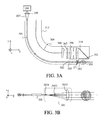
Referring to FIGS. 3A and 3B , a description will be given of a third embodiment according to the present invention. FIGS. 3A and 3B illustrate one exemplary structure of an endoscopic apparatus 313 that includes as an illumination optical system a laser transmitter according to the present invention. FIG. 3A is a yz sectional view of the endoscopic apparatus, and FIG. 3B is an xz sectional view of the sheet beam generating optical system 303 and a hollow fiber 301.
The laser beam 105 emitted from the laser light source 104 enters the hollow fiber 301 via the coupling optical system 108. The exit end of the hollow fiber 301 has an elliptical aperture 302 that is narrowed in the y direction, similar to the first embodiment. The laser beam 105 emitted from the elliptical aperture 302 of the hollow fiber 301 enters the sheet beam generating optical system 303, is emitted as a sheet beam 305 that is converged on the yz section in FIG. 3A and is parallel on the xz section in FIG. 3B , transmits a window 311, and enters a target 304. The sheet beam generating optical system 303 includes three lenses 3031, 3032, and 3033. Details of these lenses 3031, 3032, and 3033 will be described with reference to FIG. 6 and Tables 3-1 and 3-2.
The target 304 (object) generates Raman scattered light only in an area irradiated by a sheet beam 305, and the Raman scattered light transmits a window 312 and enters the observation optical system. The observation optical system is arranged so that the optical axis crosses the sheet beam 305. The observation optical system includes a reflective surface 310, an image-pickup optical system 306, and a filter 307, and the Raman scattered light emitted from the target 304 forms an image on the image sensor 308. The formed image is converted into the electric signal by the image sensor 308, and sent to the outside via a cable 309 so as to obtain a two-dimensional Raman image. In this embodiment, the image sensor 308 serves as an acquirer configured to acquire information of an image formed by the observation optical system. For the acquirer, an entrance end of a fiber bundle may be arranged instead of the image sensor 308. The fiber bundle acquires information of the image formed by the observation optical system, and sends the information to the outside of the endoscopic apparatus 313.
Due to this configuration, direct scattered light of the sheet beam 305 as excited light is hard to enter the image-pickup optical system 306, a selective excitation on a specific plane is available, and a high resolution image can be obtained in the depth direction of the image-pickup optical system 306. A three-dimensional Raman imaging can be built by moving the target 304 relative to the sheet beam 305 in the optical-axis direction of the image-pickup optical system 306 and by acquiring the Raman image at each position.
A two-dimensional Raman image can be acquired by a small structure by combining the laser transmitter and the observation optical system according to the present invention. A three-dimensional Raman image can be obtained by moving the target relative to the sheet beam.
This embodiment can provide a light guiding optical system and an endoscopic apparatus having the same, each of which has a small configuration and is advantageous to sheet beam generations.
Numerical examples 1 to 3 correspond to the sheet beam generating optical systems according to the first to third embodiments.
The present invention uses a non-rotationally symmetrical surface referred to as an anamorphic surface for the sheet beam generating optical system. This surface is defined as Expression 1. The coordinate system has a three-dimensional coordinate axes of a z-axis, a y-axis and an x-axis.
The z-axis is defined as a line that passes a center (origin of the absolute coordinate) of the first surface from the center of a 0-th surface (OBJ) and this direction is set to be positive.
The y-axis is defined as a line that passes the center (origin of the absolute coordinate) of the first surface, and forms a right angle relative to the z-axis in the counterclockwise direction.
The x-axis is defined as a line that is perpendicular to both the z-axis and the y-axis.
Herein, k is a conic coefficient. CUX/CUY is a curvature (inverse of the radius of curvature R) in each of the XY directions. Tables 1-2, 2-2, 3-2 indicate values of each of the coefficients k, AR-DR, and AP-DP. In Tables 1-1, 2-1, and 3-1, a blank column means a spherical surface shape, and AAS means that an aspheric surface shape. A surface in which all of k, AR-DR, and AP-DP are 0 is a toric surface, and expressed by TOR.
The rotationally symmetrical spherical surface is defined as Expression 2.
Similar to the non-rotationally symmetrical aspheric surface, a surface shape of rotationally symmetrical aspheric surface is expressed as AL in Table 2-1. N780 is a refractive index for light having a wavelength of 780 nm. FIGS. 4 to 6 illustrate components corresponding to surface numbers in each Table. Each figure illustrates a yz section of the sheet beam generating optical system in the corresponding numerical example. Numerical values of powers P1, P2, and P3 of the lens and surface in each numerical example will be also illustrated.
The incident NA on the optical system is 0.2 on the xz section and 0.07 on the yz section, and a target spot size is 50 μm on the yz section.
| TABLE 1-1 | |||||
| No. | Type | Rx | Ry | D | N780 |
| OBJ | 0.0000 | 0.0000 | 5.1851 | ||
| 1061a | TOR | 0.7265 | −24.8354 | 0.5000 | 1.453317 |
| 1061b | AAS | 2.3869 | −3.2077 | 0.1000 | |
| STO | 2.8121 | ||||
| 1062a | TOR | −0.8634 | 33.1374 | 1.3895 | 1.453317 |
| 1062b | AAS | −10.1489 | −61.9580 | 6.1258 | |
| 1063a | TOR | 14.9312 | 42.8561 | 1.6993 | 1.453317 |
| 1063b | TOR | −5.3914 | −7.4870 | 20.3283 | |
| IMG | |||||
| TABLE 1-2 | |||||||
| KX | KY | AR | | AP | BP | ||
| 1061b | 0.0000 | 0.0000 | −3.4573E−08 | 1.4205E−04 | 145.8410 | 7.8132E−01 | |
| KX | KY | AR | | AP | BP | ||
| 1062b | 0.0000 | 0.0000 | 1.0767E−05 | 5.2379E−05 | −13.6270 | −3.6964E−08 | |
P1=0.1237
P2=0.4739
P3=0.0839
The incident NA on the optical system is 0.2 on the xz section and 0.05 on the yz section, and a target spot size is 20 μm on the yz section.
| TABLE 2-1 | |||||
| No. | Type | Rx | Ry | D | N780 |
| OBJ | 0.0000 | 0.0000 | 2.6553 | ||
| 2071a | AL | 1.2204 | 1.2204 | 1.0600 | 1.453317 |
| 2071b | AAS | −0.3282 | 1.7321 | 0.1110 | |
| STO | 9.7818 | ||||
| 2072a | AL | 8.8921 | 8.8921 | 1.4113 | 1.453317 |
| 2072b | AAS | −8.8197 | −10.7443 | 49.4824 | |
| IMG | |||||
| TABLE 2-2 | |||||||
| | A | B | |||||
| 2071a | 0.0000 | −4.3357E−04 | −2.7961E−03 | ||||
| K.X | KY | AR | | AP | BP | ||
| 2071b | 18.5675 | −0.8148 | 2.6998E−06 | −7.0342E−03 | −251.1560 | −0.7813 | |
| | A | B | |||||
| 2072a | 0.0000 | −4.1961E−04 | −4.2960E−05 | ||||
| KX | KY | AR | | AP | BP | ||
| 2072b | −1.4270 | 0.0465 | −1.4520E−09 | −9.6334E−06 | 40.9024 | 0.1348 | |
P1=0.1802
P2=1.3764
P3=0.0513
The incident NA on the optical system is 0.25 on the xz section and 0.07 on the yz section, and a target spot size is 100 μm on the yz section.
| TABLE 3-1 | |||||
| No. | Type | Rx | Ry | D | N780 |
| OBJ | 0.0000 | 0.0000 | 2.8025 | ||
| 3031a | 1.50717 | 1.50717 | 0.8000 | 1.453317 | |
| 3031b | AAS | −0.7593 | −4.0644 | 0.4382 | |
| STO | 6.2486 | ||||
| 3032a | TOR | 1.8921 | 4.5614 | 0.5000 | 1.453317 |
| 3032b | 1.6925 | 1.6925 | 9.7360 | ||
| 3033a | 60.5364 | 60.5364 | 2.0627 | 1.453317 | |
| 3033b | TOR | −8.2070 | −4.4511 | 13.8383 | |
| IMG | |||||
| TABLE 3-2 | |||||||
| KX | KY | AR | | AP | BP | ||
| 3031b | 0.0000 | 0.0000 | 0.0862 | 0.0224 | 0.0000 | 0.0000 |
P1=0.3938
P2=0.7989
P3=0.0552
While the present invention has been described with reference to exemplary embodiments, it is to be understood that the invention is not limited to the disclosed exemplary embodiments. The scope of the following claims is to be accorded the broadest interpretation so as to encompass all such modifications and equivalent structures and functions.
For example, the light guide may be a solid optical fiber instead of the hollow optical fiber. In addition, the sheet beam generating optical system may simply collimate the light in the X direction without causing the light to diverge. Moreover, the sheet beam generating optical system may simply diverge the light in X direction without converting the diverging light into a parallel beam.
This application claims the benefit of Japanese Patent Application No. 2014-101163, filed May 15, 2014, which is hereby incorporated by reference herein in its entirety.
Claims (16)
1. A light guiding optical system comprising:
a light guide configured to guide light from an entrance end of the light guide to an exit end of the light guide by internally reflecting the light a plurality of times; and
an optical unit including a plurality of lenses configured to condense the light emitted from the exit end in a first section of a cross-section of the exit end, the first section including an optical axis of the optical unit,
wherein the exit end has an aperture that has a larger size in a first direction perpendicular to the first section than in a second direction perpendicular to a second section of the cross-section of the exit end, the second section perpendicular to the first section and including the optical axis,
wherein the exit end aperture has a size in the second direction that is smaller than a size of an aperture of the entrance end in the second direction,
wherein a lens closest to the light guide among the plurality of lenses has positive powers both in the first section and the second section of the cross-section, and
an optical power that has a size in the second section larger than a size in the first section, and
wherein the light from the exit end of the light guide enters the lens closest to the light guide among the plurality of lenses without entering any other intervening lens.
2. The light guiding optical system according to claim 1 , wherein the optical unit converts the light from the light guide into diverging light on the second section.
3. The light guiding optical system according to claim 1 , wherein the optical unit converts the light from the light guide into parallel light on the second section.
4. The light guiding optical system according to claim 1 , wherein the optical unit has a lens surface that has different powers between the first section and the second section.
5. The light guiding optical system according to claim 4 , wherein the optical unit includes a plurality of lens surfaces.
6. The light guiding optical system according to claim 1 , wherein a lens farthest from the light guide among the plurality of lenses has a positive power in the first section.
7. The light guiding optical system according to claim 1 , wherein the light guide is an optical fiber.
8. The light guiding optical system according to claim 7 , wherein the light guide is a hollow fiber.
9. The light guiding optical system according to claim 1 , wherein the optical unit forms a primary image in the optical unit in the second section.
10. The light guiding optical system according to claim 9 , wherein the optical unit telecentrically emits the light emitted from the exit end in the second section.
11. The light guiding optical system according to claim 1 , wherein a size of the aperture of the exit end in the first direction is larger than or equal to that of the entrance end in the first direction.
12. An endoscopic apparatus comprising:
a light guiding optical system configured to irradiate light onto an object;
an observation optical system configured to form an image of the object; and
an acquirer configured to acquire information of the image of the object formed by the observation optical system,
wherein the light guiding optical system includes:
a light guide configured to guide light from an entrance end of the light guide to an exit end of the light guide by internally reflecting the light a plurality of times; and
an optical unit including a plurality of lenses configured to condense the light emitted from the exit end in a first section of a cross-section of the exit end, the first section including an optical axis of the optical unit,
wherein the exit end has an aperture that has a larger size in a first direction perpendicular to the first section than in a second direction perpendicular to a second section of the cross-section of the exit end, the second section perpendicular to the first section and including the optical axis,
wherein the exit end aperture has a size in the second direction that is smaller than a size of an aperture of the entrance end in the second direction,
wherein a lens closest to the light guide among the plurality of lenses has positive powers both in the first section and the second section of the cross-section, and
an optical power that has a size in the second section larger than a size in the first section, and
wherein the light from the exit end of the light guide enters the lens closest to the light guide among the plurality of lenses without entering any other intervening lens.
13. The endoscopic apparatus according to claim 12 , wherein an optical axis of the observation optical system crosses light emitted from the optical unit.
14. The endoscopic apparatus according to claim 12 , wherein the acquirer is an image sensor.
15. The endoscopic apparatus according to claim 12 , wherein the observation optical system guides Raman scattering light emitted from the object to the acquirer.
16. A light guiding optical system comprising:
a light guide including an entrance end and an exit end configured to guide light from the entrance end to the exit end by internally reflecting the light a plurality of times; and
an optical unit including a plurality of lenses arranged along an optical axis configured to condense the light from the exit end,
wherein the entrance end is an isotropic aperture having an entrance end aperture size and the exit end is an anisotropic aperture having a first exit end aperture size in a first direction perpendicular to the optical axis and a second exit end aperture size in a second direction perpendicular to the first direction,
wherein the first exit end aperture size is larger than the second exit end aperture size and the second exit end aperture size is smaller than the entrance end aperture size,
wherein the entrance end aperture size is substantially the same as the first exit end aperture size, and
wherein a proximal lens closest to the light guide among the plurality of lenses has positive powers both in the first direction and the second direction, and an optical power of the proximal lens in the second direction is larger than that in the first direction.
Applications Claiming Priority (2)
| Application Number | Priority Date | Filing Date | Title |
|---|---|---|---|
| JP2014-101163 | 2014-05-15 | ||
| JP2014101163A JP6439089B2 (en) | 2014-05-15 | 2014-05-15 | Optical system and endoscope apparatus including the same |
Publications (2)
| Publication Number | Publication Date |
|---|---|
| US20150327756A1 US20150327756A1 (en) | 2015-11-19 |
| US10105041B2 true US10105041B2 (en) | 2018-10-23 |
Family
ID=54537524
Family Applications (1)
| Application Number | Title | Priority Date | Filing Date |
|---|---|---|---|
| US14/706,324 Active 2035-12-23 US10105041B2 (en) | 2014-05-15 | 2015-05-07 | Light guiding optical system and endoscopic apparatus having the same |
Country Status (2)
| Country | Link |
|---|---|
| US (1) | US10105041B2 (en) |
| JP (1) | JP6439089B2 (en) |
Cited By (1)
| Publication number | Priority date | Publication date | Assignee | Title |
|---|---|---|---|---|
| US12186056B2 (en) | 2021-07-13 | 2025-01-07 | Boston Scientific Scimed, Inc. | Systems and methods utilizing Raman spectroscopy for in vivo analysis |
Families Citing this family (1)
| Publication number | Priority date | Publication date | Assignee | Title |
|---|---|---|---|---|
| JP7820755B2 (en) * | 2021-10-06 | 2026-02-26 | 株式会社住田光学ガラス | Light source device for endoscope and endoscope |
Citations (18)
| Publication number | Priority date | Publication date | Assignee | Title |
|---|---|---|---|---|
| JPS535886A (en) | 1976-07-06 | 1978-01-19 | Canon Kk | Endscope |
| JPS56145866A (en) | 1980-04-14 | 1981-11-12 | Asahi Optical Co Ltd | Endoscope laser fiber coagulator |
| JPS56163665A (en) | 1980-05-20 | 1981-12-16 | Medos Kenkyusho Kk | Endoscope laser irradiating device |
| JPS58159738A (en) | 1982-03-19 | 1983-09-22 | 持田製薬株式会社 | Input and output terminal apparatus of fiber for laser knife |
| JPS59198404A (en) | 1983-04-25 | 1984-11-10 | Kinkidaigaku | Optical waveguide device for carbon dioxide laser |
| JPS62213748A (en) | 1986-03-13 | 1987-09-19 | オリンパス光学工業株式会社 | Laser knife apparatus |
| US4805984A (en) * | 1985-11-21 | 1989-02-21 | Minnesota Mining And Manufacturing Company | Totally internally reflecting light conduit |
| JPH0580217A (en) | 1991-03-29 | 1993-04-02 | Deutsche Forsch & Vers Luft Raumfahrt Ev | Flexible light guide |
| US5566267A (en) * | 1994-12-15 | 1996-10-15 | Ceram Optec Industries Inc. | Flat surfaced optical fibers and diode laser medical delivery devices |
| JPH10104523A (en) | 1996-09-26 | 1998-04-24 | Laser Tec Kk | Confocal microscope |
| JP2002288644A (en) | 2001-03-26 | 2002-10-04 | Sumita Optical Glass Inc | Line-type lighting system |
| JP2006243306A (en) | 2005-03-03 | 2006-09-14 | Yuji Matsuura | Aluminum hollow optical fiber |
| US20060222298A1 (en) * | 2005-03-31 | 2006-10-05 | Fuji Photo Film Co., Ltd. | Light source module |
| US20070091425A1 (en) | 2005-10-21 | 2007-04-26 | Olympus Corporation | Microscope examination apparatus and microscope examination method |
| JP2008250303A (en) | 2007-03-29 | 2008-10-16 | Carl Zeiss Microimaging Gmbh | Optical device for generating sheet light |
| JP2011511966A (en) | 2008-02-13 | 2011-04-14 | カール ツァイス マイクロイメージング ゲーエムベーハー | Apparatus and method for imaging a sample structure spatially with high resolution |
| JP2011167328A (en) | 2010-02-18 | 2011-09-01 | Fujifilm Corp | Photoirradiation apparatus for endoscope |
| US20120098949A1 (en) | 2010-10-22 | 2012-04-26 | Leica Microsystems Cms Gmbh | Spim microscope with a sted light sheet |
Family Cites Families (1)
| Publication number | Priority date | Publication date | Assignee | Title |
|---|---|---|---|---|
| JP2793711B2 (en) * | 1990-10-18 | 1998-09-03 | オリンパス光学工業株式会社 | Condenser for semiconductor laser |
-
2014
- 2014-05-15 JP JP2014101163A patent/JP6439089B2/en not_active Expired - Fee Related
-
2015
- 2015-05-07 US US14/706,324 patent/US10105041B2/en active Active
Patent Citations (23)
| Publication number | Priority date | Publication date | Assignee | Title |
|---|---|---|---|---|
| JPS535886A (en) | 1976-07-06 | 1978-01-19 | Canon Kk | Endscope |
| JPS56145866A (en) | 1980-04-14 | 1981-11-12 | Asahi Optical Co Ltd | Endoscope laser fiber coagulator |
| JPS56163665A (en) | 1980-05-20 | 1981-12-16 | Medos Kenkyusho Kk | Endoscope laser irradiating device |
| JPS58159738A (en) | 1982-03-19 | 1983-09-22 | 持田製薬株式会社 | Input and output terminal apparatus of fiber for laser knife |
| JPS59198404A (en) | 1983-04-25 | 1984-11-10 | Kinkidaigaku | Optical waveguide device for carbon dioxide laser |
| US4805984A (en) * | 1985-11-21 | 1989-02-21 | Minnesota Mining And Manufacturing Company | Totally internally reflecting light conduit |
| JPS62213748A (en) | 1986-03-13 | 1987-09-19 | オリンパス光学工業株式会社 | Laser knife apparatus |
| JPH0580217A (en) | 1991-03-29 | 1993-04-02 | Deutsche Forsch & Vers Luft Raumfahrt Ev | Flexible light guide |
| US5204931A (en) | 1991-03-29 | 1993-04-20 | Deutsche Forschungsanstalt Fuer Luft- Und Raumfahrt E.V. | Flexible waveguide |
| US5566267A (en) * | 1994-12-15 | 1996-10-15 | Ceram Optec Industries Inc. | Flat surfaced optical fibers and diode laser medical delivery devices |
| JPH10104523A (en) | 1996-09-26 | 1998-04-24 | Laser Tec Kk | Confocal microscope |
| JP2002288644A (en) | 2001-03-26 | 2002-10-04 | Sumita Optical Glass Inc | Line-type lighting system |
| JP2006243306A (en) | 2005-03-03 | 2006-09-14 | Yuji Matsuura | Aluminum hollow optical fiber |
| US20060222298A1 (en) * | 2005-03-31 | 2006-10-05 | Fuji Photo Film Co., Ltd. | Light source module |
| US20070091425A1 (en) | 2005-10-21 | 2007-04-26 | Olympus Corporation | Microscope examination apparatus and microscope examination method |
| JP2007114542A (en) | 2005-10-21 | 2007-05-10 | Olympus Corp | Microscope observation apparatus and microscope observation method |
| JP2008250303A (en) | 2007-03-29 | 2008-10-16 | Carl Zeiss Microimaging Gmbh | Optical device for generating sheet light |
| US20090237765A1 (en) * | 2007-03-29 | 2009-09-24 | Carl Zeiss Microimaging Gmbh | Optical arrangement for the production of a light-sheet |
| JP2011511966A (en) | 2008-02-13 | 2011-04-14 | カール ツァイス マイクロイメージング ゲーエムベーハー | Apparatus and method for imaging a sample structure spatially with high resolution |
| US8362448B2 (en) | 2008-02-13 | 2013-01-29 | Carl Zeiss Microscopy Gmbh | Apparatus and method for high spatial resolution imaging of a structure of a sample |
| JP2011167328A (en) | 2010-02-18 | 2011-09-01 | Fujifilm Corp | Photoirradiation apparatus for endoscope |
| US20120098949A1 (en) | 2010-10-22 | 2012-04-26 | Leica Microsystems Cms Gmbh | Spim microscope with a sted light sheet |
| JP2012108491A (en) | 2010-10-22 | 2012-06-07 | Leica Microsystems Cms Gmbh | Spim microscope with sequential light sheet |
Non-Patent Citations (2)
| Title |
|---|
| English translation of Office Action issued in Japanese Application No. 2014-101163 dated Mar. 20, 2018. |
| Office Action issued in Japanese Application No. 2014-101163 dated Mar. 20, 2018. |
Cited By (1)
| Publication number | Priority date | Publication date | Assignee | Title |
|---|---|---|---|---|
| US12186056B2 (en) | 2021-07-13 | 2025-01-07 | Boston Scientific Scimed, Inc. | Systems and methods utilizing Raman spectroscopy for in vivo analysis |
Also Published As
| Publication number | Publication date |
|---|---|
| US20150327756A1 (en) | 2015-11-19 |
| JP6439089B2 (en) | 2018-12-19 |
| JP2015217007A (en) | 2015-12-07 |
Similar Documents
| Publication | Publication Date | Title |
|---|---|---|
| JP5305946B2 (en) | Light guide, light source device and endoscope system | |
| JP5258613B2 (en) | Light guide, light source device and endoscope system | |
| US8705184B2 (en) | Multi-path, multi-magnification, non-confocal fluorescence emission endoscopy apparatus and methods | |
| US7643208B2 (en) | Optical scanning observation apparatus | |
| US20040242961A1 (en) | Measurement system for indirectly measuring defects | |
| WO2015182025A1 (en) | Illumination apparatus, method and medical imaging system | |
| US20130324858A1 (en) | Multi-path, multi-magnification, non-confocal fluorescence emission endoscopy apparatus and methods | |
| JP2015223462A (en) | Lighting system, lighting method, and endoscope | |
| CN108836232B (en) | Dual-mode microendoscopy devices, methods and applications | |
| US10105041B2 (en) | Light guiding optical system and endoscopic apparatus having the same | |
| US20110141252A1 (en) | Triangulation camera device and triangulation imaging method | |
| JPWO2019111360A1 (en) | Endoscope | |
| EP3570085A1 (en) | Light source device, light source control method, and image acquisition system | |
| JP5084331B2 (en) | Observation optical system | |
| US12607836B2 (en) | Optical element | |
| JP2009198736A (en) | Illuminating device and endoscope | |
| US9167957B2 (en) | Probe | |
| US20140114197A1 (en) | Probe | |
| US10111579B2 (en) | Endoscope having an illumination system shifted with respect to an imaging system to reduce generation of heat at a front-end portion of the endoscope | |
| JP2019005604A (en) | Illumination device, illumination method, endoscope system, and medical observation system | |
| JP5456710B2 (en) | Image guide and light guide integrated fiber and endoscope apparatus using the same | |
| WO2019186718A1 (en) | Optical fiber bundle, endoscope scope, and endoscope | |
| HK40087777B (en) | An optical element | |
| HK40087777A (en) | An optical element | |
| JP2014115494A (en) | Light collection optical system and observation instrument |
Legal Events
| Date | Code | Title | Description |
|---|---|---|---|
| AS | Assignment |
Owner name: CANON KABUSHIKI KAISHA, JAPAN Free format text: ASSIGNMENT OF ASSIGNORS INTEREST;ASSIGNORS:YAMAMOTO, AKIRA;SATO, HIDETOSHI;SIGNING DATES FROM 20150605 TO 20150717;REEL/FRAME:036443/0858 |
|
| STCF | Information on status: patent grant |
Free format text: PATENTED CASE |
|
| MAFP | Maintenance fee payment |
Free format text: PAYMENT OF MAINTENANCE FEE, 4TH YEAR, LARGE ENTITY (ORIGINAL EVENT CODE: M1551); ENTITY STATUS OF PATENT OWNER: LARGE ENTITY Year of fee payment: 4 |