US10104272B2 - Optical unit, imaging apparatus, and movable object - Google Patents
Optical unit, imaging apparatus, and movable object Download PDFInfo
- Publication number
- US10104272B2 US10104272B2 US14/430,781 US201314430781A US10104272B2 US 10104272 B2 US10104272 B2 US 10104272B2 US 201314430781 A US201314430781 A US 201314430781A US 10104272 B2 US10104272 B2 US 10104272B2
- Authority
- US
- United States
- Prior art keywords
- optical
- lens barrel
- optical element
- object side
- optical system
- Prior art date
- Legal status (The legal status is an assumption and is not a legal conclusion. Google has not performed a legal analysis and makes no representation as to the accuracy of the status listed.)
- Active, expires
Links
- 230000003287 optical effect Effects 0.000 title claims abstract description 316
- 238000003384 imaging method Methods 0.000 title claims abstract description 75
- 125000006850 spacer group Chemical group 0.000 claims description 23
- 230000002093 peripheral effect Effects 0.000 claims description 2
- 230000004308 accommodation Effects 0.000 description 46
- 238000010586 diagram Methods 0.000 description 11
- 238000006073 displacement reaction Methods 0.000 description 8
- 239000011347 resin Substances 0.000 description 7
- 229920005989 resin Polymers 0.000 description 7
- 230000006866 deterioration Effects 0.000 description 4
- 230000000694 effects Effects 0.000 description 3
- 238000004519 manufacturing process Methods 0.000 description 2
- 238000012986 modification Methods 0.000 description 2
- 230000004048 modification Effects 0.000 description 2
- 230000002411 adverse Effects 0.000 description 1
- 230000004075 alteration Effects 0.000 description 1
- 230000002542 deteriorative effect Effects 0.000 description 1
- 239000011521 glass Substances 0.000 description 1
- 238000003780 insertion Methods 0.000 description 1
- 230000037431 insertion Effects 0.000 description 1
- 239000002184 metal Substances 0.000 description 1
- 238000000034 method Methods 0.000 description 1
Images


Classifications
-
- H04N5/2254—
-
- B—PERFORMING OPERATIONS; TRANSPORTING
- B60—VEHICLES IN GENERAL
- B60R—VEHICLES, VEHICLE FITTINGS, OR VEHICLE PARTS, NOT OTHERWISE PROVIDED FOR
- B60R11/00—Arrangements for holding or mounting articles, not otherwise provided for
- B60R11/04—Mounting of cameras operative during drive; Arrangement of controls thereof relative to the vehicle
-
- G—PHYSICS
- G02—OPTICS
- G02B—OPTICAL ELEMENTS, SYSTEMS OR APPARATUS
- G02B7/00—Mountings, adjusting means, or light-tight connections, for optical elements
- G02B7/02—Mountings, adjusting means, or light-tight connections, for optical elements for lenses
- G02B7/021—Mountings, adjusting means, or light-tight connections, for optical elements for lenses for more than one lens
-
- G—PHYSICS
- G02—OPTICS
- G02B—OPTICAL ELEMENTS, SYSTEMS OR APPARATUS
- G02B7/00—Mountings, adjusting means, or light-tight connections, for optical elements
- G02B7/02—Mountings, adjusting means, or light-tight connections, for optical elements for lenses
- G02B7/022—Mountings, adjusting means, or light-tight connections, for optical elements for lenses lens and mount having complementary engagement means, e.g. screw/thread
-
- G—PHYSICS
- G02—OPTICS
- G02B—OPTICAL ELEMENTS, SYSTEMS OR APPARATUS
- G02B7/00—Mountings, adjusting means, or light-tight connections, for optical elements
- G02B7/02—Mountings, adjusting means, or light-tight connections, for optical elements for lenses
- G02B7/026—Mountings, adjusting means, or light-tight connections, for optical elements for lenses using retaining rings or springs
Definitions
- the present invention relates to an optical unit for improving a yield thereof, an imaging apparatus, and a movable object.
- a plurality of optical elements such as a lens and an diaphragm are provided in an optical unit.
- each of the optical elements needs to be secured in a predetermined posture at a predetermined position.
- a diaphragm wall integrally connected to an end of an opening on an imaging side of a lens barrel for accommodating the optical elements and, via an elastic member, bias the optical elements to the diaphragm wall (see PLT 1 set forth below).
- a manufacturing method described in PLT 1 in order to secure the optical elements inside the lens barrel, needs to press the optical elements from an object side of the lens barrel by using a securing member such as, for example, caulking.
- a securing member such as, for example, caulking.
- the caulking since the caulking is formed by deforming a portion of the lens barrel, the caulking may damage appearance and adversely affect an optical function of the optical element on the object side. These effects have been reducing a yield of the optical unit.
- an object of the present invention in view of the above condition is to provide an optical unit capable of improving the yield thereof, an imaging apparatus, and a movable object.
- an optical unit includes:
- an optical system including a plurality of optical elements
- a lens barrel having an object side opening smaller than an outermost periphery of an optical element closest to an object side in the optical system and an imaging side opening equal to or larger than an outermost periphery of an optical element closest to an imaging side in the optical system, the lens barrel for accommodating the optical system;
- a securing portion for securing, at the imaging side opening, the optical system inserted from the imaging side opening and accommodated in the lens barrel.
- a second aspect of the present invention is the optical unit, wherein
- the lens barrel is formed such that, in a state accommodating the optical system, an end of the lens barrel on the object side does not protrude from an optical functional surface of the optical element closest to the object side in the optical system.
- a third aspect of the present invention is the optical unit, further including a spacer interposed between the optical element closest to the imaging side in the optical system and the securing portion.
- a fourth aspect of the present invention is the optical unit, wherein
- the securing portion is caulking obtained by deforming the imaging side opening of the lens barrel.
- a fifth aspect of the present invention is the optical unit, wherein
- the lens barrel includes a screw groove at the imaging side opening, and the securing portion is a retaining member for securing the optical system by being screwed together with the lens barrel.
- a sixth aspect of the present invention is the optical unit, wherein
- the optical element on the imaging side in the optical system has an outermost periphery equal to or larger than an outermost periphery of the optical element on the object side, and each of the optical elements is fitted in the lens barrel.
- a seventh aspect of the present invention is the optical unit, further including a support portion for supporting the optical elements from peripheral sides thereof and fitting the optical elements in the lens barrel.
- an imaging apparatus includes:
- an optical unit including an optical system including a plurality of optical elements, a lens barrel having an object side opening smaller than an outermost periphery of an optical element closest to an object side in the optical system and an imaging side opening equal to or larger than an outermost periphery of an optical element closest to an imaging side in the optical system, the lens barrel for accommodating the optical system, and a securing portion for securing, at the imaging side opening, the optical system inserted from the imaging side opening and accommodated in the lens barrel;
- an image sensor for capturing an object image formed by the optical system.
- a movable object according to a ninth aspect of the present invention includes:
- an optical unit including an optical system including a plurality of optical elements, a lens barrel having an object side opening smaller than an outermost periphery of an optical element closest to an object side in the optical system and an imaging side opening equal to or larger than an outermost periphery of an optical element closest to an imaging side in the optical system, the lens barrel for accommodating the optical system, and a securing portion for securing, at the imaging side opening, the optical system inserted from the imaging side opening and accommodated in the lens barrel; and an image sensor for capturing an object image formed by the optical system.
- a yield of the optical unit may be improved.
- FIG. 1 is an arrangement diagram illustrating an installing position of an imaging apparatus having an optical unit according to a first embodiment of the present invention inside a movable object;
- FIG. 2 is a cross-sectional diagram taken along an optical axis of the optical unit in FIG. 1 ;
- FIG. 3 is a cross-sectional diagram of a lens barrel after being assembled to form the optical unit
- FIG. 4 is a cross-sectional diagram of the lens barrel before being assembled to form the optical unit
- FIG. 5 is a cross-sectional diagram of the optical unit during assembling
- FIG. 6 is a cross-sectional diagram taken along an optical axis of an optical unit according to a second embodiment
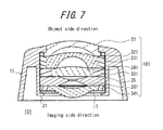
- FIG. 7 is a cross-sectional diagram taken along an optical axis of an optical unit according to a third embodiment
- FIG. 8 is a cross-sectional diagram taken along an optical axis of an optical unit using a spacer according to a first variation.
- FIG. 9 is a cross-sectional diagram taken along an optical axis of an optical unit using a spacer according to a second variation.
- FIG. 1 is an arrangement diagram illustrating an installing position of the imaging apparatus having the optical unit according to the first embodiment inside a movable object.
- an imaging apparatus 10 including an optical unit 13 is provided, together with a display apparatus 11 , to a movable object 12 .
- the imaging apparatus 10 may be located anywhere on the vehicle, the imaging apparatus 10 according to the present embodiment, in order to capture an image of a view around the vehicle as described later, is secured at a rear exterior of the movable object 12 .
- the display apparatus 11 is provided in such a manner as to be visible from a driver's seat.
- the optical unit 13 forms an object image behind the movable object on an image sensor 14 in the imaging apparatus 10 .
- the imaging apparatus 10 captures the object image by using the image sensor 14 and transmits thus captured object image to the display apparatus 11 .
- the display apparatus 11 displays the object image obtained from the image sensor 14 .
- FIG. 2 is a cross-sectional diagram taken along an optical axis of the optical unit 13 .
- the optical unit 13 includes a lens barrel 15 , an optical system 16 , and a spacer 17 .
- the lens barrel 15 includes an outer wall portion 18 and an accommodation portion 19 .
- the accommodation portion 19 is formed to be rotational symmetric about a central axis CX.
- one of sides across the central axis CX is defined as an object side, and the other is defined as an imaging side.
- the accommodation portion 19 accommodates the optical system 16 (see FIG. 2 ).
- the accommodation portion 19 has an inner surface in the cylindrical shape with a constant inner diameter (see FIG. 3 ).
- a locking portion 20 in an annular shape extending towards the central axial CX is preliminarily formed.
- a securing portion 21 is formed after assembly of the optical unit 13 .
- the optical system 16 includes a plurality of optical elements such as, for example, a first optical element 22 , a second optical element 23 , a third optical element 24 , a fourth optical element 25 , and a fifth optical element 26 .
- the first optical element 22 , the second optical element 23 , the third optical element 24 , and the fifth optical element 26 are lenses made of resin.
- the fourth optical element 24 is an aperture stop.
- the optical elements are formed and combined such that the optical system 16 has desired optical properties such as, for example, a focal length and a depth of field.
- the first optical element 22 is an optical element disposed closest to the object side in the optical system 16 .
- the first optical element 22 includes a flange portion 28 extending outward in a radial direction from a body 27 . Accordingly, the flange portion 28 corresponds to an outermost periphery of the first optical element 22 .
- An outer diameter of the body 27 substantially corresponds in size to an inner diameter of the locking portion 20 of the lens barrel 15 .
- an outer diameter of the flange portion 28 is larger than the inner diameter of the locking portion 20 and smaller than an inner diameter of the accommodation portion 19 (see FIG. 3 ).
- the body 27 and the locking portion 20 are formed in such a manner that, when the first optical element 22 is fitted in the locking portion 20 allowing the flange portion 28 to engage with the locking portion 20 , there is no step between an object side plane of the first optical element 22 and the locking portion 20 , that is, the object side plane of the first optical element 22 and the locking portion 20 are continuous without protruding from each other (see FIG. 2 ).
- Diameters of outermost peripheries of the second optical element 23 , the third optical element 24 , the fourth optical element 25 , and the fifth optical element 26 substantially correspond in size to the inner diameter of the accommodation portion 19 .
- the spacer 17 is a metal member formed into a ring shape having an inner diameter of a center hole larger than an outer diameter of a lens portion of the fifth optical element 26 responsible for an optical function. Also, an outer diameter of the spacer 17 substantially corresponds in size to the inner diameter of the accommodation portion 19 .
- the securing portion 21 is not formed at the imaging side opening of the accommodation portion 19 , and the accommodation portion 19 is continuous to an opening end maintaining a constant inner diameter.
- the first optical element 22 is inserted into the accommodation portion 19 from the imaging side (see FIG. 5 ).
- the body 27 of the first optical element 22 is fitted in the locking portion 20 of the lens barrel 15 .
- An O-ring 29 is provided between the flange portion 28 and the accommodation portion 19 .
- the second optical element 23 to the fifth optical element 26 are inserted in a sequential order into the accommodation portion 19 and fitted therein.
- the spacer 17 is inserted.
- the imaging side opening of the accommodation portion 19 is folded inward, whereby the imaging side opening is deformed and caulking serving as the securing portion 21 is formed (see FIG. 2 ).
- the diameter of the lens becomes smaller. Therefore, in order to prevent displacement of each lens in an optical axis direction, the inner diameter of the accommodation portion is generally formed to become smaller toward the imaging side. Since it has been impossible to insert, from the imaging side, the lens with the largest diameter to be positioned closest to the object side into the accommodation portion formed as described above, the optical element has conventionally been inserted from the object side and secured.
- the optical unit 13 allows the optical system 16 to be secured from the imaging side opening of the accommodation portion 19 .
- the optical unit of the first embodiment since the optical system 16 is secured from the imaging side opening of the accommodation portion 19 , an impact on the appearance of the optical unit 13 may be prevented. As described below, further, since the first embodiment is effective in preventing the impact on the appearance of the optical unit, a yield of the optical unit may be improved.
- the optical unit when the optical unit is used in a vehicle-mounted camera, the optical unit needs to satisfy an exterior projection requirement established for a vehicle.
- the conventional optical unit secured from the object side especially by forming the caulking has difficulty in satisfying the exterior projection requirement.
- the optical unit of the present embodiment since there is no impact on the appearance of the optical unit 13 , the optical unit may easily satisfy the exterior projection requirement.
- the displacement of the optical element on the object side (the first optical element 22 ) in the optical axis direction may be reduced.
- the conventional optical unit having the optical system secured from the object side tends to cause the displacement of the optical system at the time of caulking. According to the present embodiment, however, since the locking portion 20 is preliminarily formed at an end of the object side opening, the displacement may be reduced as compared with the conventional optical unit.
- the optical system 16 is secured from the imaging side opening of the accommodation portion 19 , the occurrence of vignetting may be suppressed.
- the conventional optical unit having the optical system secured from the object side may cause the vignetting due to the caulking formed larger than a design thereof and partially covering the lens. According to the present embodiment, however, since the locking portion 20 designed to prevent the vignetting is preliminarily formed at the end of the object side opening, the occurrence of the vignetting may be suppressed.
- the optical element since a lens surface of the optical element does not contact the securing portion 21 , deterioration of the optical function of the optical element may be prevented.
- the conventional optical unit having the optical system secured by the caulking formed by thermal deformation or mechanical deformation from the object side may cause mechanical deformation or thermal deformation of the lens surface, possibly deteriorating the optical function of the lens.
- the optical system 16 since the optical system 16 is secured from the imaging side where the lens surface is generally smaller than that on the object side, the optical element may engage with the securing portion 21 outside a portion of the optical element responsible for the optical function. Therefore, the deterioration of the optical function of the optical element may be prevented.
- the fifth optical element 26 is secured via the spacer 17 , all of the optical elements may be made by using resin. Since the conventional optical unit as described above may cause the mechanical deformation and the thermal deformation on the lens surface, optical elements need to be made of glass that is stronger and having higher heat resistance than resin. According to the present embodiment, however, since the spacer 17 prevents the mechanical deformation and the thermal deformation of the fifth optical element 26 , the fifth optical element secured by the caulking may be made of resin as well.
- a structure of the securing portion is different from that of the first embodiment.
- the following is a description of the second embodiment focusing on matters different from the first embodiment. Note that components having functions and structures the same as those of the first embodiment will be denoted by the same reference numerals.
- an optical unit 130 includes a lens barrel 150 , the optical system 16 , the spacer 17 , and a securing portion 210 (see FIG. 6 ).
- the structures and functions of the optical system 16 and the spacer 17 are similar to those of the first embodiment.
- the lens barrel 150 includes the outer wall portion 18 and an accommodation portion 190 .
- the structure and the function of the outer wall portion 18 are similar to those of the first embodiment.
- a male screw is formed on an outer surface of the accommodation portion 190 .
- the accommodation portion 190 is formed to be shorter in a central axis direction than the accommodation portion 19 of the first embodiment.
- the accommodation portion 190 has a length in the central axis direction covering the outer peripheries of the first optical element 22 to the fifth optical element 26 .
- the accommodation portion 190 has a structure similar to the accommodation portion 19 of the first embodiment.
- the securing portion 210 includes a cylindrical portion 300 having a female screw formed on an inner surface thereof and a locking portion 310 extending inward from an end of the cylindrical portion 300 .
- the optical unit according to the second embodiment as described above similarly to the first embodiment, has effects of preventing the impact on the appearance of the optical unit 130 , reducing the displacement, suppressing the occurrence of the vignetting, preventing the deterioration of the optical function of the optical element, and allowing for a selection of the optical element made of resin.
- the third embodiment is different from the first embodiment in terms of securing some of the lenses in the accommodation portion by using support portions.
- the following is a description of the third embodiment focusing on matters different from the first embodiment. Note that components having functions and structures the same as those of the first embodiment will be denoted by the same reference numerals.
- an optical unit 131 includes the lens barrel 15 , an optical system 161 , and the spacer 17 .
- the structures and functions of the lens barrel 15 and the spacer 17 are similar to those of the first embodiment.
- the optical system 161 includes a plurality of optical elements such as, for example, the first optical element 22 , a second optical element 231 , a third optical element 241 , the fourth optical element 25 , and a fifth optical element 261 , and also includes a first support portion 321 , a second support portion 331 , and a third support portion 341 .
- the structures and functions of the first optical element 22 and the fourth optical element 25 are the same as those of the first embodiment.
- the second optical element 231 , the third optical element 241 , and the fifth optical element 261 are made of resin and having outer diameters smaller than the inner diameter of the accommodation portion 19 .
- the first support portion 321 has an inner diameter equal to an outer diameter of the second optical element 231 and an outer diameter equal to the inner diameter of the accommodation portion 19 and supports the second optical element 231 therein.
- the second support portion 331 has an inner diameter equal to an outer diameter of the third optical element 241 and an outer diameter equal to the inner diameter of the accommodation portion 19 and supports the third optical element 241 therein.
- the third support portion 341 has an inner diameter equal to an outer diameter of the fifth optical element 261 and an outer diameter equal to the inner diameter of the accommodation portion 19 and supports the fifth optical element 26 therein.
- the first optical element 22 is inserted into the accommodation portion 19 from the imaging side.
- the second optical element 231 supported by the first support portion 321 , the third optical element 241 supported by the second support portion 331 , the fourth optical element 25 , and the fifth optical element 261 supported by the third support portion 341 are inserted in the mentioned order into the accommodation portion 19 to fit therein.
- the imaging side opening of the accommodation portion 19 is folded inward, whereby the imaging side opening is deformed and the caulking serving as the securing portion 21 is formed.
- the optical unit according to the third embodiment as described above similarly to the first embodiment, has effects of preventing the impact on the appearance of the optical unit 131 , reducing the displacement, suppressing the occurrence of the vignetting, preventing the deterioration of the optical function of the optical element, and allowing for the selection of the optical element made of resin.
- a spacer 17 may have another function as well.
- a spacer 172 may have a cylindrical portion for accommodating the second optical element 23 to the fifth optical element 26 therein so as to suppress the displacement of the optical elements in the radial direction.
- a spacer 173 may support an optical element such as, for example, an IR cut filter 353 .
- the inner surface of the accommodating portion 19 is in the cylindrical shape
- the shape of the inner surface of the accommodating portion 19 is not restrictive thereto.
- the outermost peripheries of the second optical element 23 to the fifth optical element 26 are in the circular shape and in the third embodiment the outermost peripheries of the first support portion 321 to the third support portion 341 are also in the circular shape, the shape of these outermost peripheries is not restrictive thereto.
- the first optical element 22 to the fifth optical element 26 may be accommodated in the accommodation unit 19 prior to the assembly of the optical unit 13 or 130 .
- the opening is equal to or larger than the outermost periphery of the fifth optical element 26 or the outermost periphery of the third support portion 341 ” means that a maximum width of the opening is larger than a maximum width of the fifth optical element 26 .
- the locking portion 20 of the lens barrel 15 and the flange portion 28 of the first optical element 22 are in the circular shape, the shapes of the locking portion 20 and the flange portion 28 are not restrictive thereto.
- the locking portion 20 may prevent the first optical element 22 from coming off the object side.
- the opening is smaller than the outermost periphery of the flange portion 28 ” means that a minimum width of the opening is smaller than a maximum width of the flange portion 28 .
- the second optical element 23 to the fifth optical element 26 have uniform outer diameters and, simultaneously, the accommodation portions 19 and 191 have constant diameters, when, between the optical elements adjacent to one another, the outer diameter of the optical element on the imaging side is larger than the outer diameter of the optical element on the object side and the accommodation portion has an inner diameter gradually increasing toward the imaging side, all of the optical elements may be inserted from the imaging side opening.
Landscapes
- Physics & Mathematics (AREA)
- General Physics & Mathematics (AREA)
- Optics & Photonics (AREA)
- Engineering & Computer Science (AREA)
- Mechanical Engineering (AREA)
- Lens Barrels (AREA)
Abstract
An optical unit (13) includes an optical system (16), a lens barrel (15), and a securing portion (21). The optical system (16) includes a plurality of optical elements (22 to 26). The lens barrel (15) has an object side opening smaller than an outermost periphery of the optical element (22) closest to an object side in the optical system (16). The lens barrel (15) has an imaging side opening equal to or larger than an outermost periphery of the optical element (26) closest to an imaging side in the optical system (16). The lens barrel (15) accommodates the optical system (16). The securing portion (21), at the imaging side opening, secures the optical system (16) inserted from the imaging side opening and accommodated in the lens barrel (15).
Description
This application claims priority to and the benefit of Japanese Patent Application No. 2012-211265 filed on Sep. 25, 2012, the entire contents of which are incorporated herein by reference.
The present invention relates to an optical unit for improving a yield thereof, an imaging apparatus, and a movable object.
In order to form an object image on a light receiving surface of an image sensor while suppressing aberration, a plurality of optical elements such as a lens and an diaphragm are provided in an optical unit. In order to demonstrate desired optical performance, each of the optical elements needs to be secured in a predetermined posture at a predetermined position.
As such, there is suggested to form, during manufacture of the optical unit, a diaphragm wall integrally connected to an end of an opening on an imaging side of a lens barrel for accommodating the optical elements and, via an elastic member, bias the optical elements to the diaphragm wall (see PLT 1 set forth below).
PTL 1: Japanese Patent Application Laid-Open Publication No. 2010-32902
However, a manufacturing method described in PLT 1, in order to secure the optical elements inside the lens barrel, needs to press the optical elements from an object side of the lens barrel by using a securing member such as, for example, caulking. However, since the caulking is formed by deforming a portion of the lens barrel, the caulking may damage appearance and adversely affect an optical function of the optical element on the object side. These effects have been reducing a yield of the optical unit.
Accordingly, an object of the present invention in view of the above condition is to provide an optical unit capable of improving the yield thereof, an imaging apparatus, and a movable object.
In order to solve the above problem, an optical unit according to a first aspect of the present invention includes:
an optical system including a plurality of optical elements;
a lens barrel having an object side opening smaller than an outermost periphery of an optical element closest to an object side in the optical system and an imaging side opening equal to or larger than an outermost periphery of an optical element closest to an imaging side in the optical system, the lens barrel for accommodating the optical system; and
a securing portion for securing, at the imaging side opening, the optical system inserted from the imaging side opening and accommodated in the lens barrel.
Preferably, a second aspect of the present invention is the optical unit, wherein
the lens barrel is formed such that, in a state accommodating the optical system, an end of the lens barrel on the object side does not protrude from an optical functional surface of the optical element closest to the object side in the optical system.
Preferably, a third aspect of the present invention is the optical unit, further including a spacer interposed between the optical element closest to the imaging side in the optical system and the securing portion.
Preferably, a fourth aspect of the present invention is the optical unit, wherein
the securing portion is caulking obtained by deforming the imaging side opening of the lens barrel.
Preferably, a fifth aspect of the present invention is the optical unit, wherein
the lens barrel includes a screw groove at the imaging side opening, and the securing portion is a retaining member for securing the optical system by being screwed together with the lens barrel.
Preferably, a sixth aspect of the present invention is the optical unit, wherein
the optical element on the imaging side in the optical system has an outermost periphery equal to or larger than an outermost periphery of the optical element on the object side, and each of the optical elements is fitted in the lens barrel.
Preferably, a seventh aspect of the present invention is the optical unit, further including a support portion for supporting the optical elements from peripheral sides thereof and fitting the optical elements in the lens barrel.
Also, an imaging apparatus according to an eighth aspect of the present invention includes:
an optical unit including an optical system including a plurality of optical elements, a lens barrel having an object side opening smaller than an outermost periphery of an optical element closest to an object side in the optical system and an imaging side opening equal to or larger than an outermost periphery of an optical element closest to an imaging side in the optical system, the lens barrel for accommodating the optical system, and a securing portion for securing, at the imaging side opening, the optical system inserted from the imaging side opening and accommodated in the lens barrel; and
an image sensor for capturing an object image formed by the optical system.
Further, a movable object according to a ninth aspect of the present invention includes:
an optical unit including an optical system including a plurality of optical elements, a lens barrel having an object side opening smaller than an outermost periphery of an optical element closest to an object side in the optical system and an imaging side opening equal to or larger than an outermost periphery of an optical element closest to an imaging side in the optical system, the lens barrel for accommodating the optical system, and a securing portion for securing, at the imaging side opening, the optical system inserted from the imaging side opening and accommodated in the lens barrel; and an image sensor for capturing an object image formed by the optical system.
According to the optical unit, the imaging apparatus, and the movable object structured as described above, a yield of the optical unit may be improved.
Hereinafter, embodiments of the present invention will be described with reference to the accompanying drawings.
First, an imaging apparatus having an optical unit according to a first embodiment of the present invention will be described. FIG. 1 is an arrangement diagram illustrating an installing position of the imaging apparatus having the optical unit according to the first embodiment inside a movable object.
As illustrated in FIG. 1 , an imaging apparatus 10 including an optical unit 13 is provided, together with a display apparatus 11, to a movable object 12. Although the imaging apparatus 10 may be located anywhere on the vehicle, the imaging apparatus 10 according to the present embodiment, in order to capture an image of a view around the vehicle as described later, is secured at a rear exterior of the movable object 12. The display apparatus 11 is provided in such a manner as to be visible from a driver's seat.
The optical unit 13 forms an object image behind the movable object on an image sensor 14 in the imaging apparatus 10. The imaging apparatus 10 captures the object image by using the image sensor 14 and transmits thus captured object image to the display apparatus 11. The display apparatus 11 displays the object image obtained from the image sensor 14.
A structure of the optical unit 13 will be described with reference to FIG. 2 . FIG. 2 is a cross-sectional diagram taken along an optical axis of the optical unit 13. The optical unit 13 includes a lens barrel 15, an optical system 16, and a spacer 17.
The lens barrel 15, as illustrated in FIG. 3 , includes an outer wall portion 18 and an accommodation portion 19. The accommodation portion 19 is formed to be rotational symmetric about a central axis CX. In the lens barrel 15, one of sides across the central axis CX is defined as an object side, and the other is defined as an imaging side.
The accommodation portion 19 accommodates the optical system 16 (see FIG. 2 ). The accommodation portion 19 has an inner surface in the cylindrical shape with a constant inner diameter (see FIG. 3 ). At an object side opening of the accommodation portion 19, a locking portion 20 in an annular shape extending towards the central axial CX is preliminarily formed. At an imaging side opening of the accommodation portion 19, as described later, a securing portion 21 is formed after assembly of the optical unit 13.
In FIG. 2 , the optical system 16 includes a plurality of optical elements such as, for example, a first optical element 22, a second optical element 23, a third optical element 24, a fourth optical element 25, and a fifth optical element 26. The first optical element 22, the second optical element 23, the third optical element 24, and the fifth optical element 26 are lenses made of resin. The fourth optical element 24 is an aperture stop. The optical elements are formed and combined such that the optical system 16 has desired optical properties such as, for example, a focal length and a depth of field.
The first optical element 22 is an optical element disposed closest to the object side in the optical system 16. The first optical element 22 includes a flange portion 28 extending outward in a radial direction from a body 27. Accordingly, the flange portion 28 corresponds to an outermost periphery of the first optical element 22. An outer diameter of the body 27 substantially corresponds in size to an inner diameter of the locking portion 20 of the lens barrel 15. Also, an outer diameter of the flange portion 28 is larger than the inner diameter of the locking portion 20 and smaller than an inner diameter of the accommodation portion 19 (see FIG. 3 ). The body 27 and the locking portion 20 are formed in such a manner that, when the first optical element 22 is fitted in the locking portion 20 allowing the flange portion 28 to engage with the locking portion 20, there is no step between an object side plane of the first optical element 22 and the locking portion 20, that is, the object side plane of the first optical element 22 and the locking portion 20 are continuous without protruding from each other (see FIG. 2 ).
Diameters of outermost peripheries of the second optical element 23, the third optical element 24, the fourth optical element 25, and the fifth optical element 26 substantially correspond in size to the inner diameter of the accommodation portion 19.
The spacer 17 is a metal member formed into a ring shape having an inner diameter of a center hole larger than an outer diameter of a lens portion of the fifth optical element 26 responsible for an optical function. Also, an outer diameter of the spacer 17 substantially corresponds in size to the inner diameter of the accommodation portion 19.
The following is a method of assembling the optical unit 13 as described above. As illustrated in FIG. 4 , prior to the assembly of the optical unit 13, the securing portion 21 is not formed at the imaging side opening of the accommodation portion 19, and the accommodation portion 19 is continuous to an opening end maintaining a constant inner diameter.
First, the first optical element 22 is inserted into the accommodation portion 19 from the imaging side (see FIG. 5 ). In such a manner that the flange portion 28 engages with the locking portion 20, the body 27 of the first optical element 22 is fitted in the locking portion 20 of the lens barrel 15. An O-ring 29 is provided between the flange portion 28 and the accommodation portion 19.
Next, the second optical element 23 to the fifth optical element 26 are inserted in a sequential order into the accommodation portion 19 and fitted therein. When the fifth optical element 26 is inserted into the accommodation portion 19, the spacer 17 is inserted. After the insertion of the spacer 17, the imaging side opening of the accommodation portion 19 is folded inward, whereby the imaging side opening is deformed and caulking serving as the securing portion 21 is formed (see FIG. 2 ).
In the optical system 16, generally, the further from the object side and closer to the imaging side the lens positions, the diameter of the lens becomes smaller. Therefore, in order to prevent displacement of each lens in an optical axis direction, the inner diameter of the accommodation portion is generally formed to become smaller toward the imaging side. Since it has been impossible to insert, from the imaging side, the lens with the largest diameter to be positioned closest to the object side into the accommodation portion formed as described above, the optical element has conventionally been inserted from the object side and secured.
According to the present embodiment, however, since the optical elements (the second optical element 23 to the fifth optical element 26) on the imaging side from the first optical element 22 have matching outermost peripheries, the optical elements may be inserted from the imaging side while preventing the displacement thereof in the radial direction. Therefore, unlike the conventional optical unit, the optical unit 13 according to the present embodiment allows the optical system 16 to be secured from the imaging side opening of the accommodation portion 19.
According to the optical unit of the first embodiment as described above, since the optical system 16 is secured from the imaging side opening of the accommodation portion 19, an impact on the appearance of the optical unit 13 may be prevented. As described below, further, since the first embodiment is effective in preventing the impact on the appearance of the optical unit, a yield of the optical unit may be improved.
For example, when the optical unit is used in a vehicle-mounted camera, the optical unit needs to satisfy an exterior projection requirement established for a vehicle. The conventional optical unit secured from the object side especially by forming the caulking has difficulty in satisfying the exterior projection requirement. According to the optical unit of the present embodiment, however, since there is no impact on the appearance of the optical unit 13, the optical unit may easily satisfy the exterior projection requirement.
Further, since the optical system 16 is secured from the imaging side opening of the accommodation portion 19, the displacement of the optical element on the object side (the first optical element 22) in the optical axis direction may be reduced. The conventional optical unit having the optical system secured from the object side tends to cause the displacement of the optical system at the time of caulking. According to the present embodiment, however, since the locking portion 20 is preliminarily formed at an end of the object side opening, the displacement may be reduced as compared with the conventional optical unit.
Also, since the optical system 16 is secured from the imaging side opening of the accommodation portion 19, the occurrence of vignetting may be suppressed. The conventional optical unit having the optical system secured from the object side may cause the vignetting due to the caulking formed larger than a design thereof and partially covering the lens. According to the present embodiment, however, since the locking portion 20 designed to prevent the vignetting is preliminarily formed at the end of the object side opening, the occurrence of the vignetting may be suppressed.
Also, since a lens surface of the optical element does not contact the securing portion 21, deterioration of the optical function of the optical element may be prevented. The conventional optical unit having the optical system secured by the caulking formed by thermal deformation or mechanical deformation from the object side may cause mechanical deformation or thermal deformation of the lens surface, possibly deteriorating the optical function of the lens. According to the present embodiment, however, since the optical system 16 is secured from the imaging side where the lens surface is generally smaller than that on the object side, the optical element may engage with the securing portion 21 outside a portion of the optical element responsible for the optical function. Therefore, the deterioration of the optical function of the optical element may be prevented.
According to the optical unit of the present embodiment, further, since the fifth optical element 26 is secured via the spacer 17, all of the optical elements may be made by using resin. Since the conventional optical unit as described above may cause the mechanical deformation and the thermal deformation on the lens surface, optical elements need to be made of glass that is stronger and having higher heat resistance than resin. According to the present embodiment, however, since the spacer 17 prevents the mechanical deformation and the thermal deformation of the fifth optical element 26, the fifth optical element secured by the caulking may be made of resin as well.
Next, a second embodiment of the present invention will be described. According to the second embodiment, a structure of the securing portion is different from that of the first embodiment. The following is a description of the second embodiment focusing on matters different from the first embodiment. Note that components having functions and structures the same as those of the first embodiment will be denoted by the same reference numerals.
As illustrated in FIG. 6 , an optical unit 130 includes a lens barrel 150, the optical system 16, the spacer 17, and a securing portion 210 (see FIG. 6 ). The structures and functions of the optical system 16 and the spacer 17 are similar to those of the first embodiment.
Similarly to the first embodiment, the lens barrel 150 includes the outer wall portion 18 and an accommodation portion 190. The structure and the function of the outer wall portion 18 are similar to those of the first embodiment. Unlike the first embodiment, a male screw is formed on an outer surface of the accommodation portion 190. Also, the accommodation portion 190 is formed to be shorter in a central axis direction than the accommodation portion 19 of the first embodiment. However, the accommodation portion 190 has a length in the central axis direction covering the outer peripheries of the first optical element 22 to the fifth optical element 26. Other than having the male screw and being shorter in the central axial direction, the accommodation portion 190 has a structure similar to the accommodation portion 19 of the first embodiment.
According to the second embodiment, the securing portion 210 includes a cylindrical portion 300 having a female screw formed on an inner surface thereof and a locking portion 310 extending inward from an end of the cylindrical portion 300. When the optical system 16 together with the spacer 17 are inserted in the accommodation portion 190, the cylindrical portion 300 and the accommodation portion 190 are screwed together, whereby the locking portion 310 secures the optical system 16 via the spacer 17 in the accommodation portion 190.
The optical unit according to the second embodiment as described above, similarly to the first embodiment, has effects of preventing the impact on the appearance of the optical unit 130, reducing the displacement, suppressing the occurrence of the vignetting, preventing the deterioration of the optical function of the optical element, and allowing for a selection of the optical element made of resin.
Next, a third embodiment of the present invention will be described. The third embodiment is different from the first embodiment in terms of securing some of the lenses in the accommodation portion by using support portions. The following is a description of the third embodiment focusing on matters different from the first embodiment. Note that components having functions and structures the same as those of the first embodiment will be denoted by the same reference numerals.
As illustrated in FIG. 7 , an optical unit 131 includes the lens barrel 15, an optical system 161, and the spacer 17. The structures and functions of the lens barrel 15 and the spacer 17 are similar to those of the first embodiment.
The optical system 161 includes a plurality of optical elements such as, for example, the first optical element 22, a second optical element 231, a third optical element 241, the fourth optical element 25, and a fifth optical element 261, and also includes a first support portion 321, a second support portion 331, and a third support portion 341. The structures and functions of the first optical element 22 and the fourth optical element 25 are the same as those of the first embodiment. The second optical element 231, the third optical element 241, and the fifth optical element 261 are made of resin and having outer diameters smaller than the inner diameter of the accommodation portion 19.
The first support portion 321 has an inner diameter equal to an outer diameter of the second optical element 231 and an outer diameter equal to the inner diameter of the accommodation portion 19 and supports the second optical element 231 therein. The second support portion 331 has an inner diameter equal to an outer diameter of the third optical element 241 and an outer diameter equal to the inner diameter of the accommodation portion 19 and supports the third optical element 241 therein. The third support portion 341 has an inner diameter equal to an outer diameter of the fifth optical element 261 and an outer diameter equal to the inner diameter of the accommodation portion 19 and supports the fifth optical element 26 therein.
Similarly to the first embodiment, in order to assemble the optical unit 131, first, the first optical element 22 is inserted into the accommodation portion 19 from the imaging side. Next, the second optical element 231 supported by the first support portion 321, the third optical element 241 supported by the second support portion 331, the fourth optical element 25, and the fifth optical element 261 supported by the third support portion 341 are inserted in the mentioned order into the accommodation portion 19 to fit therein. Then, similarly to the first embodiment, after the spacer 17 is inserted into the accommodation portion 19, the imaging side opening of the accommodation portion 19 is folded inward, whereby the imaging side opening is deformed and the caulking serving as the securing portion 21 is formed.
The optical unit according to the third embodiment as described above, similarly to the first embodiment, has effects of preventing the impact on the appearance of the optical unit 131, reducing the displacement, suppressing the occurrence of the vignetting, preventing the deterioration of the optical function of the optical element, and allowing for the selection of the optical element made of resin.
Although the present invention has been described based on the figures and the embodiments, it is to be understood that various modifications and changes may be implemented based on the present disclosure by those who are ordinarily skilled in the art. Accordingly, such modifications and changes are included in the scope of the present invention.
For example, although in the first to third embodiments the spacer 17 is used to protect the fifth optical elements 26 and 261, the spacer 17 may have another function as well. As illustrated in FIG. 8 , for example, a spacer 172 may have a cylindrical portion for accommodating the second optical element 23 to the fifth optical element 26 therein so as to suppress the displacement of the optical elements in the radial direction. Or, as illustrated in FIG. 9 , a spacer 173 may support an optical element such as, for example, an IR cut filter 353.
Also, although in the first to third embodiments the inner surface of the accommodating portion 19 is in the cylindrical shape, the shape of the inner surface of the accommodating portion 19 is not restrictive thereto. Further, although in the first and second embodiments the outermost peripheries of the second optical element 23 to the fifth optical element 26 are in the circular shape and in the third embodiment the outermost peripheries of the first support portion 321 to the third support portion 341 are also in the circular shape, the shape of these outermost peripheries is not restrictive thereto. When a cross-section of the accommodation portion 19 is in a polygonal shape and the outermost periphery of the optical element closest to the imaging side, i.e., the fifth optical element 26 or the outermost periphery of the third support portion 341 is in a non-circular shape, as long as the imaging side opening is equal to or larger than the outermost periphery of the fifth optical element 26 or the outermost periphery of the third support portion 341, the first optical element 22 to the fifth optical element 26 may be accommodated in the accommodation unit 19 prior to the assembly of the optical unit 13 or 130. Note that “the opening is equal to or larger than the outermost periphery of the fifth optical element 26 or the outermost periphery of the third support portion 341” means that a maximum width of the opening is larger than a maximum width of the fifth optical element 26.
Also, although in the first to third embodiments the locking portion 20 of the lens barrel 15 and the flange portion 28 of the first optical element 22 are in the circular shape, the shapes of the locking portion 20 and the flange portion 28 are not restrictive thereto. When an opening of the locking portion 20 is smaller than an outermost periphery of the flange portion 28, the locking portion 20 may prevent the first optical element 22 from coming off the object side. Note that “the opening is smaller than the outermost periphery of the flange portion 28” means that a minimum width of the opening is smaller than a maximum width of the flange portion 28.
Further, although in the first and second embodiments the second optical element 23 to the fifth optical element 26 have uniform outer diameters and, simultaneously, the accommodation portions 19 and 191 have constant diameters, when, between the optical elements adjacent to one another, the outer diameter of the optical element on the imaging side is larger than the outer diameter of the optical element on the object side and the accommodation portion has an inner diameter gradually increasing toward the imaging side, all of the optical elements may be inserted from the imaging side opening.
- 10 imaging apparatus
- 11 display apparatus
- 12 movable object
- 13, 130, 131 optical unit
- 14 image sensor
- 15, 150 lens barrel
- 16, 161 optical system
- 17, 172 spacer
- 18 outer wall
- 19, 190 accommodation portion
- 20 locking portion
- 21, 210 securing portion
- 22 first optical element
- 23 second optical element
- 24 third optical element
- 25 fourth optical element
- 26 fifth optical element
- 27 body
- 28 flange portion
- 29 O-ring
- 300 cylindrical portion
- 310 locking portion
- 321 first support portion
- 331 second support portion
- 341 third support portion
- CX central axis
Claims (11)
1. An optical unit comprising:
an optical system including a plurality of optical elements;
a lens barrel having an object side opening smaller than an outermost periphery of an optical element closest to an object side in the optical system and an imaging side opening equal to or larger than an outermost periphery of an optical element closest to an imaging side in the optical system, the lens barrel for accommodating the optical system; and
a securing portion for securing, at the imaging side opening, the optical system inserted from the imaging side opening and accommodated in the lens barrel,
wherein the lens barrel is formed such that, in a state accommodating the optical system, an end of the lens barrel on the object side does not protrude from any portion of an optical curved surface of the optical element closest to the object side in the optical system, and the optical curved surface is free from overlap with the lens barrel in an object side direction extending from the imaging side to the object side, and
the optical element closest to the object side comprises a flange portion extending outward in a radial direction from a body of the optical element closest to the object side to contact a locking portion of the lens barrel, the flange portion is formed on a first side of the optical element closest to the object side, the first side is opposite a second side of the optical element closest to the object side, and the second side includes the optical curved surface.
2. The optical unit according to claim 1 , further comprising a spacer interposed between the optical element closest to the imaging side in the optical system and the securing portion.
3. The optical unit according to claim 1 , wherein
the securing portion is caulking obtained by deforming the imaging side opening of the lens barrel.
4. The optical unit according to claim 1 , wherein
the lens barrel includes a screw groove at the imaging side opening, and the securing portion is a retaining member for securing the optical system by being screwed together with the lens barrel.
5. The optical unit according to claim 1 , wherein
the optical element on the imaging side in the optical system has an outermost periphery equal to or larger than an outermost periphery of the optical element on the object side, and each of the optical elements is fitted in the lens barrel.
6. The optical unit according to claim 1 , further comprising a support portion for supporting the optical elements from peripheral sides thereof and fitting the optical elements in the lens barrel.
7. The optical unit according to claim 1 , further comprising an O-ring provided to make contact with the outermost periphery of the optical element closest to the object side.
8. The optical unit according to claim 7 , wherein
the O-ring makes contact with the outermost periphery of the optical element closest to the object side and with two surfaces of the lens barrel.
9. An imaging apparatus comprising:
an optical unit according to claim 1 ; and
an image sensor for capturing an object image formed by the optical system.
10. A movable object having the imaging apparatus according to claim 9 mounted thereon.
11. An optical unit comprising:
an optical system including a plurality of optical elements;
a lens barrel having an object side opening smaller than an outermost periphery of an optical element closest to an object side in the optical system and an imaging side opening equal to or larger than an outermost periphery of an optical element closest to an imaging side in the optical system, the lens barrel for accommodating the optical system;
a securing portion for securing, at the imaging side opening, the optical system inserted from the imaging side opening and accommodated in the lens barrel; and
an O-ring provided to make contact with the outermost periphery of the optical element closest to the object side,
wherein the lens barrel is formed such that, in a state accommodating the optical system, an end of the lens barrel on the object side does not protrude from any portion of an optical curved surface of the optical element closest to the object side in the optical system, and the optical curved surface is free from overlap with the lens barrel in an object side direction extending from the imaging side to the object side, and
the O-ring makes contact with the outermost periphery of the optical element closest to the object side and with two surfaces of the lens barrel.
Applications Claiming Priority (3)
| Application Number | Priority Date | Filing Date | Title |
|---|---|---|---|
| JP2012211265A JP5964709B2 (en) | 2012-09-25 | 2012-09-25 | Optical unit, imaging device, and moving body |
| JP2012-211265 | 2012-09-25 | ||
| PCT/JP2013/005682 WO2014050095A1 (en) | 2012-09-25 | 2013-09-25 | Optical unit, image capture device, and mobile body |
Publications (2)
| Publication Number | Publication Date |
|---|---|
| US20150244905A1 US20150244905A1 (en) | 2015-08-27 |
| US10104272B2 true US10104272B2 (en) | 2018-10-16 |
Family
ID=50387532
Family Applications (1)
| Application Number | Title | Priority Date | Filing Date |
|---|---|---|---|
| US14/430,781 Active 2034-02-27 US10104272B2 (en) | 2012-09-25 | 2013-09-25 | Optical unit, imaging apparatus, and movable object |
Country Status (4)
| Country | Link |
|---|---|
| US (1) | US10104272B2 (en) |
| JP (1) | JP5964709B2 (en) |
| CN (1) | CN104704412B (en) |
| WO (1) | WO2014050095A1 (en) |
Cited By (2)
| Publication number | Priority date | Publication date | Assignee | Title |
|---|---|---|---|---|
| US20180315894A1 (en) * | 2017-04-26 | 2018-11-01 | Advanced Semiconductor Engineering, Inc. | Semiconductor device package and a method of manufacturing the same |
| US11125965B2 (en) | 2016-09-23 | 2021-09-21 | Fujifilm Corporation | Lens unit |
Families Citing this family (13)
| Publication number | Priority date | Publication date | Assignee | Title |
|---|---|---|---|---|
| JP2016102923A (en) * | 2014-11-28 | 2016-06-02 | 日本電産コパル株式会社 | Lens holding mechanism |
| JP2016102924A (en) * | 2014-11-28 | 2016-06-02 | 日本電産コパル株式会社 | Lens holding mechanism |
| CN106896463B (en) * | 2015-12-17 | 2020-07-31 | 宁波舜宇车载光学技术有限公司 | Optical lens for vehicle-mounted optical imaging system |
| CN206523663U (en) * | 2016-10-25 | 2017-09-26 | 瑞声科技(新加坡)有限公司 | Camera lens module |
| US20180172986A1 (en) * | 2016-12-16 | 2018-06-21 | Robert Bosch Gmbh | Camera Lens Assembly |
| JP6791745B2 (en) * | 2016-12-22 | 2020-11-25 | マクセル株式会社 | Lens unit and in-vehicle camera |
| JP6987349B2 (en) * | 2016-12-22 | 2021-12-22 | マクセル株式会社 | Lens unit and camera module |
| JP7037113B2 (en) * | 2018-02-26 | 2022-03-16 | コニカミノルタ株式会社 | Optical unit and manufacturing method of optical unit |
| US11002937B2 (en) * | 2018-03-08 | 2021-05-11 | Robert Bosch Llc | Camera lens assembly |
| WO2020258327A1 (en) * | 2019-06-28 | 2020-12-30 | 瑞声光学解决方案私人有限公司 | Optical lens |
| JP2021162730A (en) * | 2020-03-31 | 2021-10-11 | パナソニックIpマネジメント株式会社 | Imaging apparatus and visual recognition apparatus for vehicle |
| KR20220029924A (en) * | 2020-09-02 | 2022-03-10 | 엘지이노텍 주식회사 | Camera module |
| JP7094346B2 (en) * | 2020-11-02 | 2022-07-01 | マクセル株式会社 | Lens unit |
Citations (20)
| Publication number | Priority date | Publication date | Assignee | Title |
|---|---|---|---|---|
| US6507700B1 (en) * | 2000-07-10 | 2003-01-14 | Matsushita Electric Industrial Co., Ltd. | Waterproof camera |
| US6559439B1 (en) * | 1999-12-15 | 2003-05-06 | Olympus Optical Co., Ltd. | Image taking lens unit with frame member for positioning lens and substrate |
| CN1460874A (en) | 2002-05-13 | 2003-12-10 | 罗姆股份有限公司 | Image sensor assembly and its mfg. method |
| JP2007333942A (en) | 2006-06-14 | 2007-12-27 | Sharp Corp | Optical element holding mechanism, light source device, and projection display device |
| US20080024883A1 (en) * | 2006-07-28 | 2008-01-31 | Sony Corporation | Image pickup apparatus |
| JP2009103950A (en) | 2007-10-24 | 2009-05-14 | Ono Sokki Co Ltd | Lens barrel |
| JP2009157279A (en) | 2007-12-27 | 2009-07-16 | Sharp Corp | Lens unit, imaging apparatus, electronic device, and method of assembling lens unit |
| US20090225405A1 (en) * | 2006-02-03 | 2009-09-10 | Rohm Co., Ltd | Wide-Angle Lens, Optical Device Using the Wide-Angle Lens, and Method for Fabricating the Wide-Angle Lens |
| US20090244733A1 (en) * | 2008-03-28 | 2009-10-01 | Naoki Sasaki | Lens assembly and imaging apparatus |
| JP2009244773A (en) | 2008-03-31 | 2009-10-22 | Fujinon Corp | Lens assembly and imaging apparatus |
| JP2009282071A (en) | 2008-05-19 | 2009-12-03 | Fujinon Corp | Lens assembly and imaging apparatus |
| JP2010032902A (en) | 2008-07-30 | 2010-02-12 | Olympus Imaging Corp | Lens assembly |
| CN101819310A (en) | 2009-02-26 | 2010-09-01 | 阿尔卑斯电气株式会社 | Camera assembly |
| JP2010197949A (en) | 2009-02-27 | 2010-09-09 | Alps Electric Co Ltd | Camera module |
| JP2010197816A (en) | 2009-02-26 | 2010-09-09 | Alps Electric Co Ltd | Camera module |
| JP2010197950A (en) | 2009-02-27 | 2010-09-09 | Alps Electric Co Ltd | Camera module and assembly method of the same |
| JP2010211003A (en) | 2009-03-11 | 2010-09-24 | Panasonic Corp | Lens barrel device and imaging unit |
| US7965336B2 (en) * | 2002-11-14 | 2011-06-21 | Donnelly Corporation | Imaging system for vehicle |
| CN102227663A (en) | 2008-11-28 | 2011-10-26 | 住友电气工业株式会社 | Lens unit and infrared lens unit for vehicles |
| JP2012002947A (en) * | 2010-06-15 | 2012-01-05 | Fujifilm Corp | Lens barrel and lens barrel assembling method |
Family Cites Families (5)
| Publication number | Priority date | Publication date | Assignee | Title |
|---|---|---|---|---|
| JP3835619B2 (en) * | 2004-02-09 | 2006-10-18 | 京セラ株式会社 | Imaging device |
| JP2008046169A (en) * | 2006-08-10 | 2008-02-28 | Nidec Nissin Corp | Lens unit |
| CN201289538Y (en) * | 2008-03-31 | 2009-08-12 | 富士能株式会社 | Lens assembling body and photographic device |
| CN201293860Y (en) * | 2008-11-05 | 2009-08-19 | 亚洲光学股份有限公司 | Focusing integrated lens device |
| CN102662222B (en) * | 2012-05-10 | 2014-04-16 | 无锡凯尔科技有限公司 | Structure of lens and fine adjustment module and assembly technology of lens and fine adjustment module |
-
2012
- 2012-09-25 JP JP2012211265A patent/JP5964709B2/en active Active
-
2013
- 2013-09-25 WO PCT/JP2013/005682 patent/WO2014050095A1/en not_active Ceased
- 2013-09-25 US US14/430,781 patent/US10104272B2/en active Active
- 2013-09-25 CN CN201380049709.4A patent/CN104704412B/en active Active
Patent Citations (24)
| Publication number | Priority date | Publication date | Assignee | Title |
|---|---|---|---|---|
| US6559439B1 (en) * | 1999-12-15 | 2003-05-06 | Olympus Optical Co., Ltd. | Image taking lens unit with frame member for positioning lens and substrate |
| US6507700B1 (en) * | 2000-07-10 | 2003-01-14 | Matsushita Electric Industrial Co., Ltd. | Waterproof camera |
| US7352402B2 (en) | 2002-05-13 | 2008-04-01 | Rohm Co., Ltd. | Image sensor module and method of making the same |
| US20040109079A1 (en) * | 2002-05-13 | 2004-06-10 | Rohm Co., Ltd. | Image sensor module and method of making the same |
| CN1460874A (en) | 2002-05-13 | 2003-12-10 | 罗姆股份有限公司 | Image sensor assembly and its mfg. method |
| US7965336B2 (en) * | 2002-11-14 | 2011-06-21 | Donnelly Corporation | Imaging system for vehicle |
| US20090225405A1 (en) * | 2006-02-03 | 2009-09-10 | Rohm Co., Ltd | Wide-Angle Lens, Optical Device Using the Wide-Angle Lens, and Method for Fabricating the Wide-Angle Lens |
| JP2007333942A (en) | 2006-06-14 | 2007-12-27 | Sharp Corp | Optical element holding mechanism, light source device, and projection display device |
| US20080024883A1 (en) * | 2006-07-28 | 2008-01-31 | Sony Corporation | Image pickup apparatus |
| JP2009103950A (en) | 2007-10-24 | 2009-05-14 | Ono Sokki Co Ltd | Lens barrel |
| JP2009157279A (en) | 2007-12-27 | 2009-07-16 | Sharp Corp | Lens unit, imaging apparatus, electronic device, and method of assembling lens unit |
| US20090244733A1 (en) * | 2008-03-28 | 2009-10-01 | Naoki Sasaki | Lens assembly and imaging apparatus |
| JP2009244773A (en) | 2008-03-31 | 2009-10-22 | Fujinon Corp | Lens assembly and imaging apparatus |
| JP2009282071A (en) | 2008-05-19 | 2009-12-03 | Fujinon Corp | Lens assembly and imaging apparatus |
| JP2010032902A (en) | 2008-07-30 | 2010-02-12 | Olympus Imaging Corp | Lens assembly |
| CN102227663A (en) | 2008-11-28 | 2011-10-26 | 住友电气工业株式会社 | Lens unit and infrared lens unit for vehicles |
| US20120019905A1 (en) | 2008-11-28 | 2012-01-26 | Kanji Teraoka | Lens unit and vehicle-mounted infrared lens unit |
| US8456769B2 (en) | 2008-11-28 | 2013-06-04 | Sumitomo Electric Industries, Ltd. | Lens unit and vehicle-mounted infrared lens unit |
| CN101819310A (en) | 2009-02-26 | 2010-09-01 | 阿尔卑斯电气株式会社 | Camera assembly |
| JP2010197816A (en) | 2009-02-26 | 2010-09-09 | Alps Electric Co Ltd | Camera module |
| JP2010197949A (en) | 2009-02-27 | 2010-09-09 | Alps Electric Co Ltd | Camera module |
| JP2010197950A (en) | 2009-02-27 | 2010-09-09 | Alps Electric Co Ltd | Camera module and assembly method of the same |
| JP2010211003A (en) | 2009-03-11 | 2010-09-24 | Panasonic Corp | Lens barrel device and imaging unit |
| JP2012002947A (en) * | 2010-06-15 | 2012-01-05 | Fujifilm Corp | Lens barrel and lens barrel assembling method |
Non-Patent Citations (7)
| Title |
|---|
| An Office Action; "Notice of Reasons for Rejection," issued by the Japanese Patent Office dated Dec. 1, 2015, which corresponds to Japanese Patent Application No. 2012-211265 and is related to U.S. Appl. No. 14/430,781; with English language concise explanation. |
| CN Office Action dated Feb. 3, 2017 from corresponding CN Appl No. 201380049709.4, with English translation, 11 pp. |
| International Search Report; PCT/JP2013/005682; dated Dec. 10, 2013. |
| Machine English Translation of Kymoto, JP 2007333942 A, Dec. 27, 2007. * |
| Machine English Translation of Sasaki, JP 2012002947 A, Jan. 5, 2012. * |
| The First Office Action; issued by the Chinese Patent Office on Jun. 22, 2016, which corresponds to Chinese Patent Application No. 201380049709.4 and is related to U.S. Appl. No. 14/430,781; with English language translation. |
| Written Opinion of the International Searching Authority; PCT/JP2013/005682; dated Dec. 10, 2013; with concise explanation. |
Cited By (2)
| Publication number | Priority date | Publication date | Assignee | Title |
|---|---|---|---|---|
| US11125965B2 (en) | 2016-09-23 | 2021-09-21 | Fujifilm Corporation | Lens unit |
| US20180315894A1 (en) * | 2017-04-26 | 2018-11-01 | Advanced Semiconductor Engineering, Inc. | Semiconductor device package and a method of manufacturing the same |
Also Published As
| Publication number | Publication date |
|---|---|
| JP2014066824A (en) | 2014-04-17 |
| JP5964709B2 (en) | 2016-08-03 |
| CN104704412A (en) | 2015-06-10 |
| CN104704412B (en) | 2020-09-01 |
| US20150244905A1 (en) | 2015-08-27 |
| WO2014050095A1 (en) | 2014-04-03 |
Similar Documents
| Publication | Publication Date | Title |
|---|---|---|
| US10104272B2 (en) | Optical unit, imaging apparatus, and movable object | |
| EP3001233B1 (en) | Lens unit | |
| US9857553B2 (en) | Lens unit and imaging device | |
| JP7172553B2 (en) | Lens module and imaging device for vehicle | |
| US11391905B2 (en) | Lens unit and camera module | |
| JP6054819B2 (en) | Lens unit, imaging device, and moving body | |
| JP2010113016A (en) | Camera filter unit | |
| US7894714B2 (en) | Lens assembly and imaging apparatus | |
| JP2019120725A (en) | Lens unit and metal mold manufacturing method | |
| KR20170043519A (en) | Mounting system and method for night vision tubes | |
| JP6791745B2 (en) | Lens unit and in-vehicle camera | |
| JP2011075682A (en) | Optical lens | |
| JP2019109381A (en) | Lens unit and camera module | |
| JP2012088585A (en) | Optical system lens unit | |
| JP7688073B2 (en) | Lens units and camera modules | |
| JP6155167B2 (en) | Lens unit, imaging device, and in-vehicle camera | |
| WO2017216385A1 (en) | Camera for a motor vehicle, comprising an integrally formed housing top part and a lens carrier, as well as motor vehicle and method for manufacturing a camera for a motor vehicle | |
| JP2018194633A (en) | Case-integrated lens unit and camera module | |
| JP2005189261A5 (en) | ||
| JP2007225991A (en) | In-vehicle camera lens mounting structure | |
| CN102043220A (en) | Lens group and lens module with lens group | |
| JP2020030387A (en) | Lens unit and douser | |
| JP6444613B2 (en) | Lens barrel and imaging device | |
| JP7316800B2 (en) | cemented lens, lens unit and camera module | |
| JP7294767B2 (en) | Lens unit and camera module |
Legal Events
| Date | Code | Title | Description |
|---|---|---|---|
| AS | Assignment |
Owner name: KYOCERA CORPORATION, JAPAN Free format text: ASSIGNMENT OF ASSIGNORS INTEREST;ASSIGNORS:MORISHIMA, RIYOU;SUZUKI, MAKOTO;REEL/FRAME:035243/0202 Effective date: 20141215 |
|
| STCF | Information on status: patent grant |
Free format text: PATENTED CASE |
|
| MAFP | Maintenance fee payment |
Free format text: PAYMENT OF MAINTENANCE FEE, 4TH YEAR, LARGE ENTITY (ORIGINAL EVENT CODE: M1551); ENTITY STATUS OF PATENT OWNER: LARGE ENTITY Year of fee payment: 4 |