US10097938B2 - Electronic device and sound signal processing method thereof - Google Patents
Electronic device and sound signal processing method thereof Download PDFInfo
- Publication number
- US10097938B2 US10097938B2 US15/607,833 US201715607833A US10097938B2 US 10097938 B2 US10097938 B2 US 10097938B2 US 201715607833 A US201715607833 A US 201715607833A US 10097938 B2 US10097938 B2 US 10097938B2
- Authority
- US
- United States
- Prior art keywords
- sound signal
- sound
- frequency
- frequency band
- band
- Prior art date
- Legal status (The legal status is an assumption and is not a legal conclusion. Google has not performed a legal analysis and makes no representation as to the accuracy of the status listed.)
- Active
Links
- 230000005236 sound signal Effects 0.000 title claims abstract description 161
- 238000003672 processing method Methods 0.000 title abstract description 6
- 238000012545 processing Methods 0.000 claims abstract description 34
- 238000000034 method Methods 0.000 claims description 38
- 238000012937 correction Methods 0.000 claims description 9
- 208000016354 hearing loss disease Diseases 0.000 claims description 5
- 208000032041 Hearing impaired Diseases 0.000 abstract description 13
- 230000008447 perception Effects 0.000 abstract description 3
- 238000001514 detection method Methods 0.000 description 11
- 238000010586 diagram Methods 0.000 description 8
- 238000007493 shaping process Methods 0.000 description 8
- 230000014509 gene expression Effects 0.000 description 6
- 238000001228 spectrum Methods 0.000 description 6
- 238000004364 calculation method Methods 0.000 description 5
- 238000004891 communication Methods 0.000 description 5
- 230000006870 function Effects 0.000 description 3
- 241000220223 Fragaria Species 0.000 description 2
- 235000016623 Fragaria vesca Nutrition 0.000 description 2
- 235000011363 Fragaria x ananassa Nutrition 0.000 description 2
- 238000002591 computed tomography Methods 0.000 description 2
- 235000009508 confectionery Nutrition 0.000 description 2
- XLYOFNOQVPJJNP-UHFFFAOYSA-N water Substances O XLYOFNOQVPJJNP-UHFFFAOYSA-N 0.000 description 2
- 206010011878 Deafness Diseases 0.000 description 1
- 238000002583 angiography Methods 0.000 description 1
- 238000003491 array Methods 0.000 description 1
- 230000001413 cellular effect Effects 0.000 description 1
- 238000004590 computer program Methods 0.000 description 1
- 238000011161 development Methods 0.000 description 1
- 230000005611 electricity Effects 0.000 description 1
- -1 electricity Substances 0.000 description 1
- 238000005516 engineering process Methods 0.000 description 1
- 239000011521 glass Substances 0.000 description 1
- 230000010370 hearing loss Effects 0.000 description 1
- 231100000888 hearing loss Toxicity 0.000 description 1
- 238000002595 magnetic resonance imaging Methods 0.000 description 1
- 238000011160 research Methods 0.000 description 1
- 238000012360 testing method Methods 0.000 description 1
- 239000004753 textile Substances 0.000 description 1
- 238000012546 transfer Methods 0.000 description 1
- 238000005406 washing Methods 0.000 description 1
Images


Classifications
-
- H—ELECTRICITY
- H04—ELECTRIC COMMUNICATION TECHNIQUE
- H04R—LOUDSPEAKERS, MICROPHONES, GRAMOPHONE PICK-UPS OR LIKE ACOUSTIC ELECTROMECHANICAL TRANSDUCERS; DEAF-AID SETS; PUBLIC ADDRESS SYSTEMS
- H04R25/00—Deaf-aid sets, i.e. electro-acoustic or electro-mechanical hearing aids; Electric tinnitus maskers providing an auditory perception
- H04R25/70—Adaptation of deaf aid to hearing loss, e.g. initial electronic fitting
-
- G—PHYSICS
- G10—MUSICAL INSTRUMENTS; ACOUSTICS
- G10L—SPEECH ANALYSIS TECHNIQUES OR SPEECH SYNTHESIS; SPEECH RECOGNITION; SPEECH OR VOICE PROCESSING TECHNIQUES; SPEECH OR AUDIO CODING OR DECODING
- G10L21/00—Speech or voice signal processing techniques to produce another audible or non-audible signal, e.g. visual or tactile, in order to modify its quality or its intelligibility
- G10L21/003—Changing voice quality, e.g. pitch or formants
-
- G—PHYSICS
- G10—MUSICAL INSTRUMENTS; ACOUSTICS
- G10L—SPEECH ANALYSIS TECHNIQUES OR SPEECH SYNTHESIS; SPEECH RECOGNITION; SPEECH OR VOICE PROCESSING TECHNIQUES; SPEECH OR AUDIO CODING OR DECODING
- G10L21/00—Speech or voice signal processing techniques to produce another audible or non-audible signal, e.g. visual or tactile, in order to modify its quality or its intelligibility
- G10L21/02—Speech enhancement, e.g. noise reduction or echo cancellation
- G10L21/0208—Noise filtering
- G10L21/0216—Noise filtering characterised by the method used for estimating noise
- G10L21/0232—Processing in the frequency domain
-
- H—ELECTRICITY
- H04—ELECTRIC COMMUNICATION TECHNIQUE
- H04R—LOUDSPEAKERS, MICROPHONES, GRAMOPHONE PICK-UPS OR LIKE ACOUSTIC ELECTROMECHANICAL TRANSDUCERS; DEAF-AID SETS; PUBLIC ADDRESS SYSTEMS
- H04R1/00—Details of transducers, loudspeakers or microphones
- H04R1/10—Earpieces; Attachments therefor ; Earphones; Monophonic headphones
- H04R1/1083—Reduction of ambient noise
-
- H—ELECTRICITY
- H04—ELECTRIC COMMUNICATION TECHNIQUE
- H04R—LOUDSPEAKERS, MICROPHONES, GRAMOPHONE PICK-UPS OR LIKE ACOUSTIC ELECTROMECHANICAL TRANSDUCERS; DEAF-AID SETS; PUBLIC ADDRESS SYSTEMS
- H04R25/00—Deaf-aid sets, i.e. electro-acoustic or electro-mechanical hearing aids; Electric tinnitus maskers providing an auditory perception
- H04R25/35—Deaf-aid sets, i.e. electro-acoustic or electro-mechanical hearing aids; Electric tinnitus maskers providing an auditory perception using translation techniques
- H04R25/353—Frequency, e.g. frequency shift or compression
-
- H—ELECTRICITY
- H04—ELECTRIC COMMUNICATION TECHNIQUE
- H04R—LOUDSPEAKERS, MICROPHONES, GRAMOPHONE PICK-UPS OR LIKE ACOUSTIC ELECTROMECHANICAL TRANSDUCERS; DEAF-AID SETS; PUBLIC ADDRESS SYSTEMS
- H04R25/00—Deaf-aid sets, i.e. electro-acoustic or electro-mechanical hearing aids; Electric tinnitus maskers providing an auditory perception
- H04R25/45—Prevention of acoustic reaction, i.e. acoustic oscillatory feedback
- H04R25/453—Prevention of acoustic reaction, i.e. acoustic oscillatory feedback electronically
-
- H—ELECTRICITY
- H04—ELECTRIC COMMUNICATION TECHNIQUE
- H04R—LOUDSPEAKERS, MICROPHONES, GRAMOPHONE PICK-UPS OR LIKE ACOUSTIC ELECTROMECHANICAL TRANSDUCERS; DEAF-AID SETS; PUBLIC ADDRESS SYSTEMS
- H04R25/00—Deaf-aid sets, i.e. electro-acoustic or electro-mechanical hearing aids; Electric tinnitus maskers providing an auditory perception
- H04R25/50—Customised settings for obtaining desired overall acoustical characteristics
- H04R25/505—Customised settings for obtaining desired overall acoustical characteristics using digital signal processing
-
- G—PHYSICS
- G10—MUSICAL INSTRUMENTS; ACOUSTICS
- G10L—SPEECH ANALYSIS TECHNIQUES OR SPEECH SYNTHESIS; SPEECH RECOGNITION; SPEECH OR VOICE PROCESSING TECHNIQUES; SPEECH OR AUDIO CODING OR DECODING
- G10L21/00—Speech or voice signal processing techniques to produce another audible or non-audible signal, e.g. visual or tactile, in order to modify its quality or its intelligibility
- G10L21/02—Speech enhancement, e.g. noise reduction or echo cancellation
- G10L21/038—Speech enhancement, e.g. noise reduction or echo cancellation using band spreading techniques
-
- H—ELECTRICITY
- H04—ELECTRIC COMMUNICATION TECHNIQUE
- H04R—LOUDSPEAKERS, MICROPHONES, GRAMOPHONE PICK-UPS OR LIKE ACOUSTIC ELECTROMECHANICAL TRANSDUCERS; DEAF-AID SETS; PUBLIC ADDRESS SYSTEMS
- H04R2225/00—Details of deaf aids covered by H04R25/00, not provided for in any of its subgroups
- H04R2225/43—Signal processing in hearing aids to enhance the speech intelligibility
-
- H—ELECTRICITY
- H04—ELECTRIC COMMUNICATION TECHNIQUE
- H04R—LOUDSPEAKERS, MICROPHONES, GRAMOPHONE PICK-UPS OR LIKE ACOUSTIC ELECTROMECHANICAL TRANSDUCERS; DEAF-AID SETS; PUBLIC ADDRESS SYSTEMS
- H04R2430/00—Signal processing covered by H04R, not provided for in its groups
- H04R2430/03—Synergistic effects of band splitting and sub-band processing
Definitions
- the present disclosure relates generally to an electronic device and, for example, to an electronic device and sound signal processing method thereof for improving sound perception of a hearing-impaired user.
- hearing-impaired persons may have difficulty in perceiving sounds correctly in a part or the whole of a frequency band.
- a hearing aid is designed to compensate for a hearing loss by amplifying sounds in a part or the whole of the frequency band audible to the human ear.
- Conventional electronic devices e.g., hearing aid
- hearing aid are designed to shift a high frequency band signal downwards in frequency for a high frequency band hearing-impaired user. In this case, the user may hear the unperceivable high frequency band sound within the user's perceivable frequency range, but there is a difference between the real sound and the sound perceived by the user because of a change of signal waveform.
- the present disclosure provides an electronic device and sound signal processing method thereof that is capable processing a sound signal of an unperceivable frequency range of a hearing-impaired user digitally into a signal within the user's perceivable frequency range while minimizing and/or reducing the change of sound waveform.
- an electronic device includes: a sound input unit comprising sound input circuitry configured to detect a sound and to convert the sound into a first sound signal and a processor which is electrically connected to the sound input unit, the processor configured to receive the first sound signal and to perform a predetermined signal processing on the first sound signal to generate a second sound signal, wherein the signal processing comprises detecting a frequency band having a level equal to or greater than a predetermined value in a first frequency band above a predetermined cutoff frequency of the first sound signal, generating harmonic signals including a plurality of frequency bins that are identical in level with a signal in the detected frequency band, and overlapping the harmonic signals with the first sound signal.
- a sound signal correction method of an electronic device includes: detecting a first sound signal and generating a second sound signal by performing a predetermined signal processing on the first sound signal, wherein generating the second sound signal includes detecting a frequency band with a level equal to or greater than a predetermined value in a first frequency band above a predetermined cutoff frequency of the first sound signal, generating harmonic signals including a plurality of frequency bins that are identical in level with a signal in the detected frequency band, and overlapping the harmonic signals with the first sound signal.
- FIGS. 1A and 1B are diagrams illustrating an example waveform of a sound signal
- FIG. 2 is a block diagram illustrating an example configuration of an electronic device according to various example embodiments of the present disclosure
- FIG. 3 is a block diagram illustrating an example configuration of an electronic device according to various example embodiments of the present disclosure
- FIGS. 4A and 4B are graphs illustrating an example method for detecting fricative components according to various example embodiments of the present disclosure
- FIGS. 5A, 5B, 5C and 5D are graphs illustrating an example method for correcting a sound signal according to various example embodiments of the present disclosure
- FIGS. 6A, 6B and 6C are diagrams illustrating example fricative component correction procedures according to various example embodiments of the present disclosure
- FIG. 7 is a flowchart illustrating an example sound signal correction method according to various example embodiments of the present disclosure.
- FIG. 8 is a flowchart illustrating an example fricative component detection method according to various example embodiments of the present disclosure.
- the expression “A or B” or “at least A or/and B” may include A, may include B, or may include both A and B.
- the expressions “1”, “2”, “first”, or “second” used in various embodiments of the present disclosure may modify various components of the various embodiments, but they do not limit the corresponding components.
- a part e.g., first part
- another part e.g., second part
- the expression “configured to ⁇ ” may be interchangeably used with the expressions “suitable for ⁇ ”, “having a capability of ⁇ ”, “changed to ⁇ ”, “made to ⁇ ”, “capable of ⁇ ”, and “designed for” in hardware or software.
- the expression “device configured to ⁇ ” may denote that the device is “capable of ⁇ ” with other devices or components.
- the processor e.g., CPU and application processor
- the processor is capable of performing corresponding operations by executing software programs dedicated to the corresponding operations.
- An electronic device may be one or more of a smart phone, a tablet Personal Computer (PC), a mobile phone, a video phone, an e-book reader, a desktop PC, a laptop PC, a netbook computer, a Personal Digital Assistant (PDA), a portable Multimedia Player (PMP), an MP3 player, a medical device, a camera, and a wearable device, or the like, but is not limited thereto.
- a smart phone a tablet Personal Computer (PC)
- PC Personal Computer
- PDA Personal Digital Assistant
- PMP portable Multimedia Player
- MP3 player MP3 player
- the wearable device may include one of an appcessory type device (e.g., a watch, a ring, a bracelet, an anklet, a necklace, glasses, contact lens, and Head-Mounted-Device (HMD), a textile or clothes-integrated device (e.g., electronic clothes), a body-attached device (e.g., skin pad and tattoo), and a bio-implemented circuit, or the like, but is not limited thereto.
- an appcessory type device e.g., a watch, a ring, a bracelet, an anklet, a necklace, glasses, contact lens, and Head-Mounted-Device (HMD)
- a textile or clothes-integrated device e.g., electronic clothes
- a body-attached device e.g., skin pad and tattoo
- bio-implemented circuit or the like, but is not limited thereto.
- the electronic device may be one of a television (TV), a Digital Video Disk (DVD) player, an audio player, an air conditioner, a cleaner, an oven, a microwave oven, a washing machine, an air cleaner, a set-top box, a TV box (e.g., Samsung HomeSyncTM, Apple TVTM, and Google TVTM), game consoles (e.g., XboxTM and PlayStationTM), an electronic dictionary, an electronic key, a camcorder, and an electronic frame, or the like, but is not limited thereto.
- TV television
- DVD Digital Video Disk
- the electronic device may be one of a medical device (such as portable medical sensors (including a glucometer, a heart rate sensor, a tonometer, and a body thermometer), a Magnetic Resonance Angiography (MRA) device, a Magnetic Resonance Imaging (MRI) device, a Computed Tomography (CT) device, a camcorder, and a microwave scanner), a navigation device, a Global Navigation Satellite System (GNSS), an Event Data Recorder (EDR), a Flight Data Recorder (FDR), an automotive infotainment device, marine electronic equipment (such as a marine navigation system and gyro compass), aviation electronics (avionics), an automotive head unit, an industrial or household robot, an Automatic Teller Machine (ATM), a Point Of Sales (POS) terminal, and an Internet-of-Things (IoT) device (such as an electric bulb, sensor, sprinkler system, fire alarm system, temperature controller, street lamp, toaster, fitness equipment, hot water tank, heater, and a Global Navigation
- examples of the electronic device may include furniture, a building/structure, a part of a vehicle, an electronic board, an electronic signature receiving device, a projector, and a sensor (such as water, electricity, gas, and electric wave meters), or the like, but is not limited thereto.
- the electronic device may be flexible or a combination of at least two of the aforementioned devices.
- the electronic device is not limited to the aforementioned devices.
- the term “user” may denote a person who uses the electronic device or a device (e.g., artificial intelligent electronic device) which uses the electronic device.
- module may, for example, refer to, but is not limited to, a unit of one of software, hardware, and firmware or any combination thereof.
- the term “module” may be used interchangeably with the terms “unit,” “logic,” “logical block,” “component,” or “circuit.”
- the term “module” may denote a smallest unit of a component or a part thereof.
- the term “module” may be the smallest unit of performing at least one function or a part thereof.
- a module may be implemented mechanically or electronically.
- a module may include at least one of a dedicated processor, a CPU, an Application-Specific Integrated Circuit (ASIC) chip, Field-Programmable Gate Arrays (FPGAs), and Programmable-Logic Device known or to be developed for certain operations.
- the devices e.g., modules or their functions
- methods e.g., operations
- an electronic device may be a hearing aid.
- the hearing aid is designed to amplify a signal in a part or the whole of a frequency band to a predetermined level in order for a hearing-impaired user to perceive the corresponding sound.
- Various embodiments of the present disclosure are directed to an electronic device as a hearing aid or a hearing aid function-equipped multifunctional device such as a smartphone and a tablet Personal Computer (PC).
- the electronic device is not limited to those specified in the embodiments, and it may be any type of electronic device capable of processing sound signals.
- the first sound signal may be a digital signal obtained by converting an analog sound collected by a sound input unit (e.g., including sound input circuitry) of an electronic device or a sound signal stored in the electronic device or received from an external device.
- the second sound signal may be a signal obtained by correcting a high frequency band signal as a signal processing result of a processor of the electronic device.
- the term “cutoff frequency (fc)” may refer, for example, to a maximum frequency value of a sound which the user of the electronic device can perceive correctly.
- a hearing-impaired user of the electronic device may not perceive a sound signal on a frequency equal to or higher than the cutoff frequency.
- a fricative sound such as [s] and [ ⁇ ] is a high-frequency phoneme produced in the frequency range of 4 kHz to 7 kHz, although there is variation depending on the speaker. If the upper limit of a user's hearing ability is 4 kHz, the user cannot perceive the sound signal of a higher frequency above 4 kHz. For this reason, it is necessary to determine a hearing-impaired user's cutoff frequency by analyzing the user's hearing characteristics through various pre-tests.
- FIGS. 1A to 8 Various example embodiments of the present disclosure are described hereinafter with reference to FIGS. 1A to 8 .
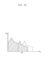
- FIGS. 1A and 1B are diagrams illustrating an example waveform of a sound signal.
- FIG. 1A is a graph illustrating an amplitude curve of the first sound signal in the frequency domain according to an embodiment of the present disclosure.
- the horizontal axis denotes frequency
- the vertical axis denotes a signal level or amplitude.
- the graph of FIG. 1A may illustrate the size of a frequency component at a specific time or during a time period.
- the first sound signal is divided into a low frequency band and a high frequency band by a cutoff frequency (fc).
- the cutoff frequency may be an upper frequency limit of sound perceivable by the user of the electronic device, and the cutoff frequency value is determined statistically.
- the high frequency band has a part of high frequency as denoted by reference number 110 .
- Such a component with a high signal level is likely to be a meaningful component in the real sound, but the user of the electronic device may not perceive the high-level signal component because the high-level signal component is within the high frequency band above the cutoff frequency.
- Such a signal component is likely to be a fricative component as illustrated in FIG. 1B .
- FIG. 1B is a graph illustrating the signal level of the first sound signal in the time domain.
- FIG. 1B illustrates change in frequency of a sound signal, as time goes by, when the saying “Strawberry jam is sweet” made by somebody is input to the electronic device.
- the horizontal axis denotes time
- the vertical axis denotes frequency.
- the frequency level may increases as shown in the graph.
- FIG. 2 is a block diagram illustrating an example configuration of an electronic device according to various example embodiments of the present disclosure.
- the electronic device 200 includes a sound input unit (e.g., including sound input circuitry) 210 , a processor (e.g., including processing circuitry) 220 , a sound output unit (e.g., including sound output circuitry) 230 , and a memory 240 .
- a sound input unit e.g., including sound input circuitry
- a processor e.g., including processing circuitry
- a sound output unit e.g., including sound output circuitry
- the sound input unit 210 may include various sound input circuitry and detect a sound and convert the sound to a first sound signal. According to various embodiments of the present disclosure, the sound input unit 210 collects sounds around the electronic device 200 to acquire a sound signal in an analog format, and converts the analog signal to a digital signal. In order to accomplish this, the sound input unit 210 may include various circuitry, such as, for example, and without limitation, an Analog-to-Digital (A/D) converter, which can be implemented in hardware and/or software. The sound input unit 210 may be implemented in the form of a well-known device such as a microphone.
- A/D Analog-to-Digital
- the first sound signal may be a sound signal stored in the memory 240 of the electronic device 200 or received from an external device.
- the electronic device 200 may amplify and/or convert the sound signal generated by the electronic device 200 and the external device as well as the sound signal collected by the sound input unit 210 .
- the electronic device 200 may include a radio communication module (not shown) to receive sound signals from the external device.
- the memory 240 may include a well-known volatile memory and/or non-volatile memory without restriction in the implementation thereof.
- the memory 240 may be electrically connected to the processor 220 and store various instructions executable by the processor 220 . Such instructions may include control commands for arithmetical and logical computation, data transfer, and input/output operation.
- the instructions of the processor 220 to be described hereinbelow may be carried out by loading the instructions stored in the memory 240 .
- the memory 240 may store a cutoff frequency value.
- the cutoff frequency may be an upper frequency limit of the sound that the user of the electronic device 200 can correctly perceive and may be predetermined by analyzing the hearing characteristics of the user.
- the processor 220 may include various processing circuitry and is configured to control the components of the electronic device 200 and perform communication-related operations and data processing.
- the processor 220 may be electrically and/or functionally connected to internal components (such as the sound input unit 210 , the sound output unit 230 , and the memory 240 ) of the electronic device 200 .
- the processor 220 may receive the first sound signal output from the sound input unit 210 and perform a predetermined signal processing on the first sound signal to generate a second sound signal.
- the processor 220 may amplify the signal level of a part or the whole of the frequency band of the first sound signal to generate the second sound signal.
- the processor 220 may also detect a fricative component in a high frequency band above the cutoff frequency of the first sound signal and perform signal processing to correct the fricative component to a signal within the low frequency band below the cutoff frequency.
- the processor 220 may perform a detection routine for detecting a frequency band having a level higher than a predetermined level in the high frequency band above the cutoff frequency, a harmonic generation routing for generating harmonic signals including a plurality of frequency bins having the same level as the signal of the detected frequency band, and an envelope shaping routine for overlapping the harmonic signals with the first sound signal and adjusting the levels of the frequency bins.
- the signal processing operation of the processor 220 is described in greater detail below with reference to FIGS. 3 to 6 .
- the second sound signal generated as a result of the signal processing operation of the processor 220 may be output to the sound output unit 230 , which may include various sound output circuitry and is electrically connected to the processor 220 .
- the sound output unit 230 may include sound output circuitry, such as, for example, and without limitation, a Digital-to-Analog (D/A) converter for converting the second sound signal as a digital signal to an analog signal.
- the sound output unit 230 may be implemented in the form of a well-known device such as a speaker outputting sound, a receiver, and an earphone.
- the user who cannot perceive signals in the high frequency band above the cutoff frequency may perceive the fricative component of the second sound signal output from the sound output unit 230 .
- the electronic device 200 may further include a communication module including various communication circuitry for supporting at least one of, for example, and without limitation, cellular, Wi-Fi, and Bluetooth communications, an input device such as a key input device and a touch panel, a display, a battery, and a Power Management Module (or Power Management Integrated Circuit (PMIC)).
- a communication module including various communication circuitry for supporting at least one of, for example, and without limitation, cellular, Wi-Fi, and Bluetooth communications, an input device such as a key input device and a touch panel, a display, a battery, and a Power Management Module (or Power Management Integrated Circuit (PMIC)).
- a communication module including various communication circuitry for supporting at least one of, for example, and without limitation, cellular, Wi-Fi, and Bluetooth communications, an input device such as a key input device and a touch panel, a display, a battery, and a Power Management Module (or Power Management Integrated Circuit (PMIC)).
- PMIC Power Management Integrated Circuit
- FIG. 3 is a block diagram illustrating an example configuration of an electronic device according to various example embodiments of the present disclosure.
- the first sound signal output from the sound input unit (e.g., including sound input circuitry) 310 may be input to the processor (e.g., including processing circuitry) 320 .
- the processor 320 may perform a detection routing 322 for detecting the first sound signal.
- the processor 320 may detect a frequency band having a level higher than a predetermined level in the first frequency band (or high frequency band) above a predetermined cutoff frequency of the first sound signal in the detection routing 322 .
- the frequency band having a level higher than a predetermined level in the first frequency band may be the frequency band of the fricative component represented by pronunciation symbols such as [s] and [ ⁇ ].
- the processor 320 may detect a frequency bin of a sub-band with the highest power among a plurality of sub-bands (e.g., sub-bands with a bandwidth of 150 Hz) constituting the frequency band of the first sound signal.
- the processor 320 may skip the harmonic generation routing 324 and envelope shaping routing 328 and amplify the signal level in a part or the whole of the frequency band of the first sound signal to generate the second sound signal.
- the fricative component detection routine 322 is described later in greater detail below with reference to FIGS. 4A and 4B .
- the processor 320 may generate harmonic signals (h 1 to hn) including a plurality of frequency bins.
- the frequency bins may have a predetermined period in the frequency band and appear in a part or the whole of the frequency band.
- the signal level of each frequency bin may have the same level as the signal of the frequency band (fricative component) detected in the detection routine 322 or be substantially identical with a level having a tolerable difference.
- the processor 320 may overlap the generated harmonic signals with the first sound signal as denoted by reference number 326 . As described above, since the level of each frequency bin of the harmonic signal is substantially identical with the fricative component, some frequency bins may have a level higher than the first sound signal of same frequency band.
- the processor 320 may perform the envelop shaping routine 328 on the overlapped signal.
- the processor 320 may adjust the level of at least one frequency bin of the high frequency band (or first frequency band) among the plural frequency bins included in the harmonic signals so as to be equal to the level of the first sound signal in the same frequency band.
- each frequency bin of the harmonic signal may be maintained as overlapped in the low frequency band below the cutoff frequency and may become equal to or lower than the level of the first sound signal as the original signal.
- the signal before performing the envelop shaping routine 328 thereon may have harmonic signals with a level higher than that of the first sound signal; thus, the input sound may be distorted.
- the level of the harmonic signal is adjusted to be lower than that of the first sound signal in the high frequency band through the envelope shaping routine 328 , thereby making it possible for the user to perceive the fricative component of the high frequency band while minimizing distortion of the input sound.
- the second sound signal generated as a result of performing the envelope shaping routine 328 may be output to the sound output unit 330 .
- the sound output unit 330 may output the second sound signal.
- the processor may detect a harmonic component in the first sound signal and perform the above-described signal processing routines (e.g., the detection routine, the harmonic generation routine, and the envelope shaping routine) only when a fricative component exists.
- FIGS. 4A and 4B relate to a method for detecting a fricative component and illustrate example graphs explaining how to detect a flatness of a frequency spectrum and to compute a power value.
- FIG. 4A illustrates graphs of example frequency signal level curves at each of time t 1 , t 2 , and t 3 .
- times t 1 , t 2 , and t 3 may be specific time points or time periods.
- three time points or time periods are indicated in FIG. 4A for convenience of explanation, more than three signal spectrums can be used.
- the processor may divide a predetermined sensing band into a plurality of sub-bands.
- the sensing band is a frequency band (e.g., frequency band between 4 kHz and 7 kHz) in which the fricative sounds [s] and [ ⁇ ] are detected.
- the sensing band may be determined by measuring the frequency band in which the fricative sounds appear regardless of the characteristics of the user of the electronic device, while the cutoff frequency is determined, as described above, according to the characteristics of the user.
- the sub-bands may have the same bandwidth of 100 to 150 Hz.
- an, bn, and cn may denote the same frequency band.
- the processor determines that the flatness is less than the threshold value and thus checks for the presence of a fricative component in the corresponding sub-band.
- the processor may calculate power values in the sensing band and a frequency band below the sensing band.
- the frequency band is divided into two parts by the lower limit value of the sensing band (e.g., 4 kHz for the sensing band between 4 kHz and 7 kHz), i.e., low frequency band below the lower limit of the sensing band and high frequency band above the lower limit of the sensing band.
- the processor calculates a Low Frequency Power (LFP) of the low frequency band and a High Frequency Power (HFP) of the high frequency band.
- LFP Low Frequency Power
- HFP High Frequency Power
- the LFP may be calculated as a power value in the frequency band between 0 and 4 kHz as the lower limit of the sensing band, and the HFP as a power value in the frequency band between 4 kHz as the low limit of the sensing band and ⁇ .
- the HFP is defined as the power value in the range between 4 kHz and ⁇ , it may be replaced by a Band Frequency Power (BFP) in the sensing band (between 4 kHz and 7 kHz) because the signal level of the sound signal is low in the range above 7 kHz.
- BFP Band Frequency Power
- the processor determines the presence of a fricative component and performs a signal processing for correcting the fricative component. If the power of the high frequency band is high, this means that the sound signal has many high frequency components at the corresponding time point (or during the corresponding time period); thus, it is necessary to correct the high frequency components to output a sound audible to the user.
- FIGS. 5A, 5B, 5C and 5D are graphs illustrating an example method for correcting a sound signal according to various example embodiments of the present disclosure.
- the operations of the processor to be described with reference to FIGS. 5A and 5B may be performed when a fricative component is detected as described with reference to FIGS. 4A and 4B .
- FIG. 5A illustrates the first sound signal
- fricative component in a frequency band above a cutoff frequency as shown in the drawing, and the signal level of the fricative component is given as L 0 .
- the processor e.g., processor 220 of FIG. 2 and processor 320 of FIG. 3
- the processor may detect a fricative component in the detection routine (as denoted by reference number 322 of FIG. 3 ).
- a fricative component in the detection routine (as denoted by reference number 322 of FIG. 3 ).
- FIG. 5B illustrates harmonic signals
- FIG. 5C illustrates the overlap of the first sound signal and the harmonic signals.
- the processor may adjust the level of at least one frequency bin of the high frequency band (or first frequency band) among the plural frequency bins included in the harmonic signals so as to be equal to the level of the first sound signal in the same frequency band.
- the frequency bins h 2 and h 3 in the high frequency band may be adjusted to h 2 ′ and h 3 ′ according to the level of the first sound signal.
- each frequency bin of the harmonic signal may be maintained as overlapped in the low frequency band below the cutoff frequency (e.g., h 1 ′) and may become equal to or lower than the level of the first sound signal as the original signal (e.g., h 2 and h 3 ).
- the second sound signal generated from the first sound signal through the signal processing procedure as described with reference to FIGS. 5A to 5D may be output through a sound output unit (sound output unit 230 of FIG. 2 or sound output unit 330 of FIG. 3 ).
- the electronic device may shift a high frequency band having a fricative component to a low frequency band in the frequency spectrum.
- the fricative component may be shifted to the low frequency band below the cutoff frequency.
- this embodiment has a drawback of causing significant distortion of the real sound because the signal level varies even in the low frequency band that is independent of the fricative component and the change in the high frequency band is relatively large.
- the electronic device may include a sound input unit comprising sound input circuitry which detects a sound and converts the sound to a first sound signal, and a processor which is electrically connected to the sound input unit, and configured to receive the first sound signal and which is configured to perform a predetermined signal processing procedure on the first sound signal to generate a second sound signal, and the signal processing procedure includes detecting a frequency band having a level equal to or greater than a predetermined value in the first frequency band above a predetermined cutoff frequency of the first sound signal, generating harmonic signals including a plurality of frequency bins with the same level as the signal in the detected frequency band, and overlapping the harmonic signals with the first sound signal.
- At least one of the plural frequency bins included in the harmonic signals may be present in a second frequency band below the cutoff frequency.
- the signal processing procedure performed by the processor may further include adjusting the level of at least one frequency bin belonging to the first frequency band among the plural frequency bins included in the harmonic signals to the level of the first sound signal in the same frequency band.
- the processor performs the signal processing procedure when a fricative component is present in the first sound signal, and checking for presence of the fricative component includes dividing a sensing band predetermined in the first sound signal into a plurality of sub-bands, calculating flatness of the sub-bands, and calculating power values of the sensing band and a frequency band below the sensing band.
- the processor may determine the presence of the fricative component and perform the signal processing procedure when the flatness is less than a threshold value and a ratio between the power value of the sensing band and the power value of the frequency band below the sensing band is greater than a threshold value.
- the sensing band is a frequency band between 4 kHz and 7 kHz.
- the electronic device further includes a sound output unit which is electrically connected to the processor and outputs the second sound signal.
- the sound signal correction method may be performed by the electronic device 200 of FIG. 2 and/or the electronic device 300 of FIG. 3 , and detailed descriptions of technical features that have been made above are omitted herein.
- the processor may receive the first sound signal output from the sound input unit.
- the processor may detect a fricative component. Step 720 is described in greater detail below with reference to FIG. 8 .
- the procedure goes to step 780 .
- the processor may output the first sound signal with or without amplifying a specific frequency band or the whole frequency band thereof.
- the processor may detect a frequency band having a level equal to or greater than a predetermined value in the first frequency band (or high frequency band) above a predetermined cutoff frequency of the first sound signal.
- the frequency band having a level equal to or greater than the predetermined value in the first frequency band may be the frequency band of a fricative component represented by a pronunciation symbol such as [s] and [ ⁇ ].
- the processor may generate harmonic signals h 1 to hn including a plurality of frequency bins.
- the frequency bins may have a predetermined period in the frequency band and appear in a part or the whole of the frequency band.
- the signal level of each frequency bin may have the same level as the signal of the frequency band (fricative component) detected at step 720 or be substantially identical with a level having a tolerable difference.
- the harmonic signals are generated as described with reference to FIG. 5B .
- the processor may overlap the harmonic signals with the first sound signal.
- the signals may be overlapped as described with reference to FIG. 5C .
- the processor may adjust the level of at least one frequency bin of the high frequency band (or first frequency band) among the plural frequency bins included in the harmonic signals so as to be equal to the level of the first sound signal in the same frequency band.
- each frequency bin of the harmonic signal may be maintained as overlapped in the low frequency band below the cutoff frequency and may become equal to or lower than the level of the first sound signal as the original signal.
- the second sound signal may be generated as described with reference to FIG. 5D .
- the processor may output the second sound signal generated based on the first sound signal to the sound output unit, which outputs the second sound signal.
- FIG. 8 is a flowchart illustrating an example fricative component detection method according to various example embodiments of the present disclosure.
- the processor may divide a predetermined sensing band of sound signals at plural time points or time periods into a plurality of sub-bands.
- the sensing band is a frequency band (e.g., frequency band between 4 kHz and 7 kHz) in which the fricative sounds [s] and [ ⁇ ] are detected.
- the processor may determine a flatness per sub-band.
- the arithmetic mean and geometric mean of the nth sub-band may be calculated as (an+bn+cn)/3 and (an*bn*cn) ⁇ (1 ⁇ 3), respectively, where an, bn, and cn may denote mean values of the respective sub-bands (e.g., ⁇ (an/bandwidth of an))df).
- the processor may determine whether the flatness (e.g., ratio between the geometric mean and the arithmetic means) is less than a predetermined value (geometric mean/arithmetic mean ratio ⁇ ) and, if so, check for the presence of a fricative component in the corresponding sub-band. If not, the processor may check for non-presence of a fricative component at step 870 .
- the fricative sound detection may be performed as described with reference to FIG. 4A .
- the processor may determine power values in the sensing band and a frequency band below the sensing band.
- the power value calculation may be performed as described with reference to FIG. 4B .
- the processor may determine whether the ratio between the power values of the sensing band (or high frequency band) and the frequency band below the sensing band (or low frequency band) is greater than a predetermined threshold value (HFP/LFP> ⁇ ) and, if so, check for the presence of a fricative component at step 860 .
- a predetermined threshold value HFP/LFP> ⁇
- a sound signal correction method of an electronic device includes generating a first sound signal and acquiring a second sound signal by performing a predetermined signal processing on the first sound signal, wherein acquiring the second sound signal includes detecting a frequency band with a level equal to or greater than a predetermined value in a first frequency band above a predetermined cutoff frequency of the first sound signal, generating harmonic signals including a plurality of frequency bins that are identical in level with a signal in the detected frequency band, and overlapping the harmonic signals with the first sound signal.
- the frequency bins include at least one frequency bin existing in a second frequency band below the cutoff frequency.
- acquiring a second sound signal comprises adjusting the level of at least one frequency bin belonging to the first frequency band among the frequency bins included in the harmonic signals to the level of the first sound signal in the same frequency band.
- determining whether the fricative component exists includes checking, when the flatness is less than a predetermined threshold value and a ratio between the power values of the sensing band and the frequency band delimited below the sensing band is greater than a predetermined threshold value, that the fricative component exists.
- the sensing band is a frequency band between 4 kHz and 7 kHz.
- the method further includes storing the cutoff frequency determined according to hearing characteristics of a user.
- the method further includes outputting the second sound signal.
- outputting the second sound signal includes generating the second sound signal by compensating the first sound signal for a user's hearing-impairment components in the first frequency band.
- the electronic device is a hearing aid.
- the electronic device and sound signal processing method of the present disclosure is advantageous in terms of improving the sound perception of a hearing-impaired user by processing a sound signal of an unperceivable frequency range of the hearing-impaired user digitally into a signal within the user's perceivable frequency range while minimizing and/or reducing the change of sound waveform.
Landscapes
- Engineering & Computer Science (AREA)
- Signal Processing (AREA)
- Physics & Mathematics (AREA)
- Acoustics & Sound (AREA)
- Health & Medical Sciences (AREA)
- General Health & Medical Sciences (AREA)
- Otolaryngology (AREA)
- Neurosurgery (AREA)
- Quality & Reliability (AREA)
- Human Computer Interaction (AREA)
- Multimedia (AREA)
- Audiology, Speech & Language Pathology (AREA)
- Computational Linguistics (AREA)
- Circuit For Audible Band Transducer (AREA)
Applications Claiming Priority (2)
| Application Number | Priority Date | Filing Date | Title |
|---|---|---|---|
| KR10-2016-0068347 | 2016-06-01 | ||
| KR1020160068347A KR102494080B1 (ko) | 2016-06-01 | 2016-06-01 | 전자 장치 및 전자 장치의 사운드 신호 보정 방법 |
Publications (2)
| Publication Number | Publication Date |
|---|---|
| US20170353806A1 US20170353806A1 (en) | 2017-12-07 |
| US10097938B2 true US10097938B2 (en) | 2018-10-09 |
Family
ID=60482476
Family Applications (1)
| Application Number | Title | Priority Date | Filing Date |
|---|---|---|---|
| US15/607,833 Active US10097938B2 (en) | 2016-06-01 | 2017-05-30 | Electronic device and sound signal processing method thereof |
Country Status (2)
| Country | Link |
|---|---|
| US (1) | US10097938B2 (ko) |
| KR (1) | KR102494080B1 (ko) |
Families Citing this family (1)
| Publication number | Priority date | Publication date | Assignee | Title |
|---|---|---|---|---|
| CN109410973B (zh) * | 2018-11-07 | 2021-11-16 | 北京达佳互联信息技术有限公司 | 变声处理方法、装置和计算机可读存储介质 |
Citations (8)
| Publication number | Priority date | Publication date | Assignee | Title |
|---|---|---|---|---|
| US4843623A (en) * | 1986-05-23 | 1989-06-27 | University De Franche-Comte | Hearing aid devices in which high frequency signal portions are transposed in low frequency compenstion signal portions |
| US7248711B2 (en) | 2003-03-06 | 2007-07-24 | Phonak Ag | Method for frequency transposition and use of the method in a hearing device and a communication device |
| US20070253585A1 (en) * | 2006-04-27 | 2007-11-01 | Siemens Aktiengesellschaft | Time-adaptive adjustment of a hearing aid apparatus and corresponding method |
| US20080254753A1 (en) | 2007-04-13 | 2008-10-16 | Qualcomm Incorporated | Dynamic volume adjusting and band-shifting to compensate for hearing loss |
| US8031892B2 (en) | 2005-06-27 | 2011-10-04 | Widex A/S | Hearing aid with enhanced high frequency reproduction and method for processing an audio signal |
| US8107654B2 (en) | 2008-05-21 | 2012-01-31 | Starkey Laboratories, Inc | Mixing of in-the-ear microphone and outside-the-ear microphone signals to enhance spatial perception |
| US20150073784A1 (en) | 2013-09-10 | 2015-03-12 | Huawei Technologies Co., Ltd. | Adaptive Bandwidth Extension and Apparatus for the Same |
| US9031269B2 (en) * | 2010-09-29 | 2015-05-12 | Siemens Medical Instruments Pte. Ltd. | Method and device for frequency compression with selective frequency shifting |
Family Cites Families (2)
| Publication number | Priority date | Publication date | Assignee | Title |
|---|---|---|---|---|
| US7177808B2 (en) * | 2000-11-29 | 2007-02-13 | The United States Of America As Represented By The Secretary Of The Air Force | Method for improving speaker identification by determining usable speech |
| WO2012076044A1 (en) * | 2010-12-08 | 2012-06-14 | Widex A/S | Hearing aid and a method of improved audio reproduction |
-
2016
- 2016-06-01 KR KR1020160068347A patent/KR102494080B1/ko active IP Right Grant
-
2017
- 2017-05-30 US US15/607,833 patent/US10097938B2/en active Active
Patent Citations (8)
| Publication number | Priority date | Publication date | Assignee | Title |
|---|---|---|---|---|
| US4843623A (en) * | 1986-05-23 | 1989-06-27 | University De Franche-Comte | Hearing aid devices in which high frequency signal portions are transposed in low frequency compenstion signal portions |
| US7248711B2 (en) | 2003-03-06 | 2007-07-24 | Phonak Ag | Method for frequency transposition and use of the method in a hearing device and a communication device |
| US8031892B2 (en) | 2005-06-27 | 2011-10-04 | Widex A/S | Hearing aid with enhanced high frequency reproduction and method for processing an audio signal |
| US20070253585A1 (en) * | 2006-04-27 | 2007-11-01 | Siemens Aktiengesellschaft | Time-adaptive adjustment of a hearing aid apparatus and corresponding method |
| US20080254753A1 (en) | 2007-04-13 | 2008-10-16 | Qualcomm Incorporated | Dynamic volume adjusting and band-shifting to compensate for hearing loss |
| US8107654B2 (en) | 2008-05-21 | 2012-01-31 | Starkey Laboratories, Inc | Mixing of in-the-ear microphone and outside-the-ear microphone signals to enhance spatial perception |
| US9031269B2 (en) * | 2010-09-29 | 2015-05-12 | Siemens Medical Instruments Pte. Ltd. | Method and device for frequency compression with selective frequency shifting |
| US20150073784A1 (en) | 2013-09-10 | 2015-03-12 | Huawei Technologies Co., Ltd. | Adaptive Bandwidth Extension and Apparatus for the Same |
Also Published As
| Publication number | Publication date |
|---|---|
| US20170353806A1 (en) | 2017-12-07 |
| KR102494080B1 (ko) | 2023-02-01 |
| KR20170136362A (ko) | 2017-12-11 |
Similar Documents
| Publication | Publication Date | Title |
|---|---|---|
| US10939218B2 (en) | Method for detecting wrong positioning of earphone, and electronic device and storage medium therefor | |
| US10237651B2 (en) | Audio signal processing method and electronic device for supporting the same | |
| US9892721B2 (en) | Information-processing device, information processing method, and program | |
| US9681219B2 (en) | Orientation free handsfree device | |
| EP2925020A1 (en) | Method for adapting sound of hearing aid and hearing aid and electronic device performing the same | |
| KR20170055329A (ko) | 노이즈를 제거하는 방법 및 이를 위한 전자 장치 | |
| KR20200086476A (ko) | 전자기 신호를 측정하기 위한 방법 및 그 전자 장치 | |
| US9847767B2 (en) | Electronic device capable of adjusting an equalizer according to physiological condition of hearing and adjustment method thereof | |
| KR102267520B1 (ko) | 자외선 검출 방법 및 그 전자 장치 | |
| KR102216881B1 (ko) | 전자장치에서 마이크의 감도에 따른 자동 이득 조절 방법 및 장치 | |
| US9928851B2 (en) | Voice verifying system and voice verifying method which can determine if voice signal is valid or not | |
| US20210392452A1 (en) | Wear detection | |
| CN113746983A (zh) | 助听方法及装置、存储介质、智能终端 | |
| US10097938B2 (en) | Electronic device and sound signal processing method thereof | |
| KR102256287B1 (ko) | 전자장치의 심박수 측정장치 및 방법 | |
| US9998610B2 (en) | Control apparatus, control method, and computer-readable medium | |
| US9723417B2 (en) | Apparatus for inputting audiogram using touch input | |
| KR20200074599A (ko) | 전자장치 및 그 제어방법 | |
| KR20200013513A (ko) | 스피커에 포함된 진동판을 이용하여 하우징 내부 공간의 액체를 외부로 배출하는 전자 장치, 및 그 전자 장치의 제어 방법 | |
| KR101773401B1 (ko) | 음향 처리 방법, 이를 수행하기 위한 기록 매체 및 장치 | |
| JP5289529B2 (ja) | 電子機器、音響信号の補正方法およびプログラム | |
| CN111757211A (zh) | 降噪方法、终端设备及存储介质 | |
| US9282397B2 (en) | Acoustic signal corrector and acoustic signal correcting method | |
| US10897665B2 (en) | Method of decreasing the effect of an interference sound and sound playback device | |
| CN113870883A (zh) | 应用于电视机的语音信号处理方法、装置、介质及设备 |
Legal Events
| Date | Code | Title | Description |
|---|---|---|---|
| AS | Assignment |
Owner name: SAMSUNG ELECTRONICS CO., LTD., KOREA, REPUBLIC OF Free format text: ASSIGNMENT OF ASSIGNORS INTEREST;ASSIGNORS:LEE, JAESEONG;BANG, KYOUNGHO;KIM, KYUHAN;AND OTHERS;REEL/FRAME:042612/0383 Effective date: 20170407 |
|
| STCF | Information on status: patent grant |
Free format text: PATENTED CASE |
|
| MAFP | Maintenance fee payment |
Free format text: PAYMENT OF MAINTENANCE FEE, 4TH YEAR, LARGE ENTITY (ORIGINAL EVENT CODE: M1551); ENTITY STATUS OF PATENT OWNER: LARGE ENTITY Year of fee payment: 4 |