US10090683B2 - Battery management system for controlling an energy storage assembly and method for charging and discharging an energy storage assembly - Google Patents
Battery management system for controlling an energy storage assembly and method for charging and discharging an energy storage assembly Download PDFInfo
- Publication number
- US10090683B2 US10090683B2 US15/036,742 US201415036742A US10090683B2 US 10090683 B2 US10090683 B2 US 10090683B2 US 201415036742 A US201415036742 A US 201415036742A US 10090683 B2 US10090683 B2 US 10090683B2
- Authority
- US
- United States
- Prior art keywords
- accumulator
- physical quantity
- value
- accumulator modules
- discharging
- Prior art date
- Legal status (The legal status is an assumption and is not a legal conclusion. Google has not performed a legal analysis and makes no representation as to the accuracy of the status listed.)
- Expired - Fee Related, expires
Links
- 238000007599 discharging Methods 0.000 title claims abstract description 132
- 238000000034 method Methods 0.000 title claims abstract description 14
- 238000004146 energy storage Methods 0.000 title abstract description 12
- 230000008859 change Effects 0.000 claims abstract description 42
- 230000004044 response Effects 0.000 claims description 2
- 230000008569 process Effects 0.000 abstract description 3
- 230000005856 abnormality Effects 0.000 description 47
- 230000002159 abnormal effect Effects 0.000 description 10
- 229910001416 lithium ion Inorganic materials 0.000 description 9
- 230000009467 reduction Effects 0.000 description 9
- HBBGRARXTFLTSG-UHFFFAOYSA-N Lithium ion Chemical compound [Li+] HBBGRARXTFLTSG-UHFFFAOYSA-N 0.000 description 7
- 230000002950 deficient Effects 0.000 description 7
- 238000005259 measurement Methods 0.000 description 7
- WHXSMMKQMYFTQS-UHFFFAOYSA-N Lithium Chemical compound [Li] WHXSMMKQMYFTQS-UHFFFAOYSA-N 0.000 description 4
- 238000001514 detection method Methods 0.000 description 4
- 238000010586 diagram Methods 0.000 description 4
- 230000006870 function Effects 0.000 description 4
- 229910052744 lithium Inorganic materials 0.000 description 4
- 230000004913 activation Effects 0.000 description 3
- 238000012544 monitoring process Methods 0.000 description 3
- 230000008901 benefit Effects 0.000 description 2
- 230000007423 decrease Effects 0.000 description 2
- 238000012423 maintenance Methods 0.000 description 2
- 230000001681 protective effect Effects 0.000 description 2
- 229910005580 NiCd Inorganic materials 0.000 description 1
- 229910005813 NiMH Inorganic materials 0.000 description 1
- 230000032683 aging Effects 0.000 description 1
- 230000006399 behavior Effects 0.000 description 1
- 230000000052 comparative effect Effects 0.000 description 1
- 230000007547 defect Effects 0.000 description 1
- 230000001419 dependent effect Effects 0.000 description 1
- 238000002955 isolation Methods 0.000 description 1
- 230000002045 lasting effect Effects 0.000 description 1
- 230000007774 longterm Effects 0.000 description 1
- 238000004519 manufacturing process Methods 0.000 description 1
- 230000000737 periodic effect Effects 0.000 description 1
- 230000000306 recurrent effect Effects 0.000 description 1
- 230000035945 sensitivity Effects 0.000 description 1
- 230000035882 stress Effects 0.000 description 1
Images


Classifications
-
- H—ELECTRICITY
- H02—GENERATION; CONVERSION OR DISTRIBUTION OF ELECTRIC POWER
- H02J—CIRCUIT ARRANGEMENTS OR SYSTEMS FOR SUPPLYING OR DISTRIBUTING ELECTRIC POWER; SYSTEMS FOR STORING ELECTRIC ENERGY
- H02J7/00—Circuit arrangements for charging or depolarising batteries or for supplying loads from batteries
- H02J7/0013—Circuit arrangements for charging or depolarising batteries or for supplying loads from batteries acting upon several batteries simultaneously or sequentially
- H02J7/0014—Circuits for equalisation of charge between batteries
-
- G—PHYSICS
- G01—MEASURING; TESTING
- G01R—MEASURING ELECTRIC VARIABLES; MEASURING MAGNETIC VARIABLES
- G01R19/00—Arrangements for measuring currents or voltages or for indicating presence or sign thereof
- G01R19/165—Indicating that current or voltage is either above or below a predetermined value or within or outside a predetermined range of values
- G01R19/16533—Indicating that current or voltage is either above or below a predetermined value or within or outside a predetermined range of values characterised by the application
- G01R19/16538—Indicating that current or voltage is either above or below a predetermined value or within or outside a predetermined range of values characterised by the application in AC or DC supplies
- G01R19/16542—Indicating that current or voltage is either above or below a predetermined value or within or outside a predetermined range of values characterised by the application in AC or DC supplies for batteries
-
- G01R31/3658—
-
- G—PHYSICS
- G01—MEASURING; TESTING
- G01R—MEASURING ELECTRIC VARIABLES; MEASURING MAGNETIC VARIABLES
- G01R31/00—Arrangements for testing electric properties; Arrangements for locating electric faults; Arrangements for electrical testing characterised by what is being tested not provided for elsewhere
- G01R31/36—Arrangements for testing, measuring or monitoring the electrical condition of accumulators or electric batteries, e.g. capacity or state of charge [SoC]
- G01R31/396—Acquisition or processing of data for testing or for monitoring individual cells or groups of cells within a battery
-
- H02J7/0021—
-
- H—ELECTRICITY
- H02—GENERATION; CONVERSION OR DISTRIBUTION OF ELECTRIC POWER
- H02J—CIRCUIT ARRANGEMENTS OR SYSTEMS FOR SUPPLYING OR DISTRIBUTING ELECTRIC POWER; SYSTEMS FOR STORING ELECTRIC ENERGY
- H02J7/00—Circuit arrangements for charging or depolarising batteries or for supplying loads from batteries
- H02J7/0047—Circuit arrangements for charging or depolarising batteries or for supplying loads from batteries with monitoring or indicating devices or circuits
-
- H—ELECTRICITY
- H02—GENERATION; CONVERSION OR DISTRIBUTION OF ELECTRIC POWER
- H02J—CIRCUIT ARRANGEMENTS OR SYSTEMS FOR SUPPLYING OR DISTRIBUTING ELECTRIC POWER; SYSTEMS FOR STORING ELECTRIC ENERGY
- H02J7/00—Circuit arrangements for charging or depolarising batteries or for supplying loads from batteries
- H02J7/007—Regulation of charging or discharging current or voltage
-
- H—ELECTRICITY
- H02—GENERATION; CONVERSION OR DISTRIBUTION OF ELECTRIC POWER
- H02J—CIRCUIT ARRANGEMENTS OR SYSTEMS FOR SUPPLYING OR DISTRIBUTING ELECTRIC POWER; SYSTEMS FOR STORING ELECTRIC ENERGY
- H02J7/00—Circuit arrangements for charging or depolarising batteries or for supplying loads from batteries
- H02J7/14—Circuit arrangements for charging or depolarising batteries or for supplying loads from batteries for charging batteries from dynamo-electric generators driven at varying speed, e.g. on vehicle
-
- H02J7/1461—
-
- H02J2007/005—
-
- H—ELECTRICITY
- H02—GENERATION; CONVERSION OR DISTRIBUTION OF ELECTRIC POWER
- H02J—CIRCUIT ARRANGEMENTS OR SYSTEMS FOR SUPPLYING OR DISTRIBUTING ELECTRIC POWER; SYSTEMS FOR STORING ELECTRIC ENERGY
- H02J7/00—Circuit arrangements for charging or depolarising batteries or for supplying loads from batteries
- H02J7/0047—Circuit arrangements for charging or depolarising batteries or for supplying loads from batteries with monitoring or indicating devices or circuits
- H02J7/0048—Detection of remaining charge capacity or state of charge [SOC]
-
- Y—GENERAL TAGGING OF NEW TECHNOLOGICAL DEVELOPMENTS; GENERAL TAGGING OF CROSS-SECTIONAL TECHNOLOGIES SPANNING OVER SEVERAL SECTIONS OF THE IPC; TECHNICAL SUBJECTS COVERED BY FORMER USPC CROSS-REFERENCE ART COLLECTIONS [XRACs] AND DIGESTS
- Y02—TECHNOLOGIES OR APPLICATIONS FOR MITIGATION OR ADAPTATION AGAINST CLIMATE CHANGE
- Y02T—CLIMATE CHANGE MITIGATION TECHNOLOGIES RELATED TO TRANSPORTATION
- Y02T10/00—Road transport of goods or passengers
- Y02T10/60—Other road transportation technologies with climate change mitigation effect
- Y02T10/70—Energy storage systems for electromobility, e.g. batteries
-
- Y02T10/7011—
-
- Y02T10/7055—
Definitions
- the invention relates to a battery management system for controlling an energy accumulator (or energy storage) arrangement, and in particular for controlling a charging or discharging operation of an energy accumulator arrangement. Furthermore, the invention relates to an energy accumulator arrangement having a plurality of accumulator modules connected in series, which energy accumulator arrangement is controlled by an aforementioned battery management system. The invention further relates to a method for charging or discharging an aforementioned energy accumulator arrangement.
- lithium-ion accumulators are used for energy storage, in particular in electric and hybrid vehicles, but also in many other areas, such as portable electronic devices.
- the advantage of lithium-ion accumulators is a particularly high energy density along with low volume and weight.
- a drawback of lithium-ion accumulators is that they are very sensitive to overcharging, so that an operation within the prescribed tolerance limits and thus a long service life of the lithium-ion accumulators can only be ensured with appropriate protective circuits.
- lithium-ion accumulators are also referred to as lithium-ion cells.
- Energy accumulator arrangements in electric and hybrid vehicles, but also in other battery-powered devices, are usually composed of a series connection of several accumulator modules, wherein one accumulator module may have a plurality of cells.
- the cells are usually installed in so-called accumulator packs or sheets, wherein the individual cells within these sheets can only to a limited extent be monitored separately.
- the cells are connected in series and/or in parallel.
- the individual accumulator packs or accumulator modules have separate terminals, that allow the voltage to be checked and the cells located in said accumulator module to be charged and discharged individually. During a charging or discharging operation the voltage of the individual accumulator modules is monitored by the battery management system.
- a battery management system monitors the charging and discharging of an energy accumulator arrangement comprising a plurality of accumulator modules connected in series, wherein the accumulator modules are formed by several interconnected cells.
- lithium-based accumulator modules have a high sensitivity for too low and too high voltages, which have to be monitored and prevented by a battery management system.
- the battery management system monitors, in addition to the charging and discharging, the temperature and also takes over the control of the charge equalization between the individual accumulator modules, if necessary.
- the battery management system serves as an interface between the electrical loads or generators incorporated into the vehicle and the accumulator modules incorporated into the battery.
- the battery management system both monitors the battery and controls the battery depending on the function or operating state of the vehicle.
- the battery management system performs, for example, the activation of the battery during the operation of the vehicle or the standby control when the vehicle is not moving, or performs the charging operation when the battery of the vehicle is charged when it is not operational.
- the battery management system in particular includes contactors to control an electrical isolation between the battery and the electric components of the vehicle.
- the battery management system performs the function of opening the contactors in case corresponding sensors of the vehicle are responsive and thus completely electrically and galvanically isolating the energy accumulator arrangement from the vehicle.
- an object of the invention is to provide a battery management system for controlling an energy accumulator arrangement or a method for charging or discharging an energy accumulator arrangement which solves the aforementioned problems.
- the battery management system according to the invention or the method according to the invention allows temporary abnormalities within the accumulator modules or the cells during charging or discharging of accumulator modules to be responded to and the charging or discharging operation of the accumulator modules or the entire energy accumulator arrangement to be controlled accordingly.
- the invention is based on the idea that, in the accumulator modules of the energy accumulator arrangement, which are connected in series, not only uniform parameter profiles or profiles of physical quantities arise during charging or discharging. According to the invention, deviations in the parameter profiles, even if they are within the range end-of-charge voltage and end-of-discharge voltage, are detected and taken into account in the continued control of charging and discharging.
- the battery management system includes a measuring device for detecting at least one value of a physical quantity of the accumulator modules and a control device controlling the discharge or charging current based on the detected physical value of at least one of the accumulator modules.
- control device checks, whether a value of a physical quantity of one of the accumulator modules is changing faster than the corresponding values of a physical quantity of the other accumulator modules of the energy accumulator arrangement and/or whether a value of a physical quantity of one of the accumulator modules is changing faster than a predetermined change value for the physical quantity.
- the battery management system preferably includes a memory device in which the values of physical quantities of accumulator modules are stored.
- values of physical quantities can be stored therein, in order to judge whether one of the measured physical quantities such as voltage, current or temperature behaves differently than the comparative values stored in the memory device.
- a given change value for the monitored physical quantity may be stored in the memory device. That is, it is stored in the memory device, how much the voltage, the temperature or the current may change per unit of time, respectively.
- the control device acts upon the discharging current or charging current accordingly.
- the battery management system is coupled to a device for current limitation or comprises a device for current limitation in order to influence the charging or discharging current.
- the internal or external device for current limitation is activated or deactivated in response to control signals of the control device so as to limit the charging current or the discharging current, respectively, which is fed to the accumulator modules of the energy accumulator arrangement or drawn therefrom.
- the battery management system alternatively outputs a control signal to control an internal or external device for current limitation which is received by an external control device of the electrical load or a charging device and influences the load or the charging operation accordingly.
- a control signal is output to the on-board computer of an electric vehicle by the control device in order to inform it that an abnormality has occurred in the energy accumulator arrangement and, for example, only a reduced current is available for the load.
- the accumulator module By reducing and/or completely terminating the charging/discharging operation in case of a determined abnormality or anomaly, the accumulator module is given the opportunity to return to a state situated within the normal range with the help of a lower load or a lower charging current.
- the abnormal states in accumulator modules are reached, in particular, by working with maximum charging currents or discharging currents, by which the accumulator modules are lead to the edge of their load limits.
- Other reasons for the occurrence of temporary abnormalities during charging or discharging may be manufacturing tolerances or aging of cells in the accumulator modules.
- an abnormality may occur due to the physical structure and a resultant different burden on the individual cells or due to a partial defect (e.g.
- the value of a physical quantity is preferably continuously detected by the battery management system according to the invention. If the deviating or abnormal value of the physical quantity returns to a normal range, the load limitation or the limitation of the charging current can be suspended. It may be provided that the battery management system, in particular the affected accumulator module, in which the abnormality has occurred, continues to be monitored.
- the invention proposes to counter this abnormality with a different or enhanced measure.
- the control device checks whether a voltage value of one of the accumulator modules changes more rapidly than the voltage values of the other accumulator modules of the energy accumulator arrangement or whether a voltage value of one of the accumulator modules changes more rapidly than a voltage change value stored in the memory device. If a deviation or abnormality is detected during charging, that is, a voltage change value is exceeded at one of the accumulator modules or the voltage rises more rapidly here than in the other accumulator modules, a charging current limitation is activated for all accumulator modules.
- a discharging current limitation is activated for all accumulator modules. That is, according to the invention both a more rapid rise in the voltage or generally in the value of a physical quantity or a faster drop in a voltage or generally in a value of a physical quantity in one of the accumulator modules is monitored and, consequently, a charging current limitation or a discharging current limitation is activated for all accumulator modules.
- control device deactivates the charging current limitation after the voltage change value is again consistent with the values of the other accumulator modules or the stored values.
- control device prefferably, it is also possible for the control device to deactivate the discharging current limitation after dropping below the voltage change or another predetermined voltage change value. That is, in the case in which the rise or the drop of the monitored value of the physical quantity returns to a normal range, the charging current limitation or the discharging current limitation is deactivated.
- the charging current or discharging current limitation is maintained or gradually reduced. If the charging current or discharging current limitation is maintained, the energy accumulator arrangement, for example, has to undergo maintenance before the original applicable charging currents or discharging currents are re-enabled.
- different voltage change values are stored for different charging current values and/or for different voltage change values are stored for different discharging current values and the limitation of the charging or discharging currents is adjusted depending on the charging current values or discharging current values.
- the limitation will be more strict in case of an abnormality than at a lower discharging current, since the chance of damage to the accumulator module is greater for a very high discharging current and an abnormality than for a low discharging current, for which the discharging current has to be limited less strictly in case of an abnormality of.
- an energy accumulator arrangement including a plurality of accumulator modules electrically connected in series comprising a battery management system described above.
- the object is also achieved by a method for charging and discharging a energy accumulator arrangement, wherein the energy accumulator arrangement includes a plurality of accumulator modules electrically connected in series.
- the method comprises the steps of detecting at least one value of a physical quantity of the accumulator module; checking whether a value of a physical quantity of one of the accumulator modules changes more rapidly than a value of the physical quantity of the other accumulator modules of the energy accumulator arrangement or whether a value of a physical quantity of one of the accumulator modules changes more rapidly than a predetermined change value for a physical quantity and controlling the discharging current or the charging current, which is drawn from or supplied to the accumulator modules based on the check.
- the battery management system according to the invention makes it possible for the cells or the accumulator modules in case of abnormalities to return to their normal range without completely deactivating the energy accumulator arrangement and thus to ensure a continued use of the device or electric vehicle.
- FIG. 1 shows a schematic diagram of a first battery management system according to the invention.
- FIG. 2 shows a schematic diagram of a battery management system according to a second exemplary embodiment.
- FIG. 3 is a flow chart for the charging operation of an energy accumulator arrangement using a battery management system according to the invention.
- FIG. 4 is a flow chart for the discharging operation of an energy accumulator arrangement using a battery management system according to the invention.
- FIG. 5 is a flow chart of another exemplary embodiment according to the invention.
- FIG. 6 is a diagram for illustrating the charging of 100% functional or partly defective energy accumulator arrangements.
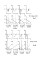
- FIG. 7 shows voltage and current profiles for illustrating the invention during discharging.
- FIG. 8 shows voltage and current profiles for illustrating the invention during charging.
- FIG. 1 shows a battery management system 100 for controlling an energy accumulator arrangement 10 .
- the energy accumulator arrangement 10 includes four accumulator modules 11 , 12 , 14 and 14 . In this example, these are connected in series.
- accumulator modules 11 , 12 , 13 and 14 a plurality of cells are connected in parallel or in series, wherein the individual accumulator modules in the energy accumulator arrangement 10 are then connected in series.
- the interconnection of the individual cells within the accumulator modules then has an impact on the voltage applied at the external terminals of the accumulator modules.
- the accumulator modules 11 , 12 , 13 and 14 connected in series may include any number of cells connected in parallel, as ideal cells connected in parallel behave as one large cell.
- the energy accumulator arrangement 10 is connected to a control device 20 .
- the control device 20 has a voltage monitoring functionality that detects the voltage across each accumulator module 11 , 12 , 13 and 14 .
- the control device 20 is connected to the individual accumulator modules 11 , 12 , 13 and 14 via a voltage detection bus 18 .
- the battery management system includes an ammeter or a device for current measurement 15 . Said ammeter 15 is connected to a supply line in order to measure the charging or discharging current and provide this value to the control device 20 .
- control device 20 may instruct the device for current measurement 15 , when a current value is to be detected or when it is to be transmitted to the control device 20 . This means that the detection period can be adjusted.
- the battery management system includes, in one embodiment, a current limitation unit 30 .
- the current limitation unit 30 is connected to both supply lines to the energy accumulator arrangement 10 and is controlled by the control device 20 .
- the control device 20 also includes an input 16 via which signals from one or more external systems or from a load are received. Moreover, the control device 20 includes an output 17 via which via the signals are transmitted to external systems or to a load 40 .
- the load 40 which is powered by the energy accumulator arrangement 10 may, for example, be an electric motor.
- the load 40 may, in addition to the actual load M, also comprise a control unit 41 , which receives signals from the control device 20 in addition to signals from other external devices.
- the control unit 41 in the load 40 outputs signals which are transmitted, inter alia, to the controller 201 as well as to external components.
- the current limitation unit 30 also comprises terminals 31 via which the energy accumulator arrangement 10 is charged during the charging process.
- the terminals 31 may alternatively be located outside of the current limitation unit 30 to supply a charging current from a charger 32 during charging.
- controllable switches are included in the current limitation unit 30 via which the supplied charging current or the drawn discharging current can be controlled.
- the switches may be pulsed, so that the current amount (charge amount) can be reduced with respect to a unit of time.
- FIG. 2 shows an alternative embodiment of a battery management system.
- the energy accumulator arrangement 10 is structured analogously to the energy accumulator arrangement shown in FIG. 1 .
- the control device 20 in the alternative embodiment communicates with the charger 32 or with the load 40 . That is, in the second exemplary embodiment of the battery management system according to the invention not device for current limitation is provided, since the control device 20 communicates directly with the charger or the load and their control units and thus can act upon the limitation of the charging current or the discharging current in a very detailed manner.
- FIG. 3 shows a flow chart in which the method for controlling the discharging operation of the accumulator modules is described.
- the accumulator modules are discharged in step S 200 .
- the voltage drop at each of the accumulator modules 11 , 12 , 13 , and 14 is measured continuously or periodically and fed to the control device 20 via the bus 18 .
- the control device 20 converts the detected voltages into digital values and compares these voltage values with values stored in the accumulator module of the control device 20 or in an external (not shown) memory arrangement.
- the control device 20 checks, whether the voltage drop in one of the accumulator modules 11 , 12 , 13 , or 14 is higher or greater than in other accumulator modules 11 , 12 , 13 , or 14 . If there no abnormal voltage drop, which is greater than a defined value and/or greater than in the other accumulator modules, is detected, the accumulator modules are discharged further.
- control device 20 detects such an abnormal voltage drop, a signal is output to the current limitation unit 30 or to the load 40 and/or their control unit 41 , thereby limiting the discharging current.
- control unit 41 of the load 40 may limit the motor speed, so as to reduce the drawn current (discharging current) thereby.
- the latter may limit the current drain, i.e. the discharging current, by a pulsed switch.
- the current limitation unit 30 may interrupt the current drain completely, wherein the current limitation unit 30 interrupts the lines to the load, for example, by means of one or a plurality of switches.
- control device 20 outputs a signal to the load unit 40 or current limitation unit 30 to suspend the limitation of the load.
- step S 240 If the voltage drop during the checking in step S 240 is not lower than a defined value, the limitation of the discharging current of step S 230 is maintained. While not shown, it is then possible to tighten the limitation. If the checking has a positive result, charge is drawn S 260 limitlessly after terminating S 250 the limitation of the accumulator modules, wherein in step S 210 a further continuous or periodic checking of the voltage drop is performed in each of the accumulator modules during the discharging operation.
- FIG. 4 a flow chart of a discharging operation of an energy accumulating arrangement 10 including a battery management system 100 according to the invention is shown.
- step S 400 the accumulator modules are charged and/or the charging process is started.
- step S 410 the voltage at each accumulator module is detected via the bus 18 during charging and the detected voltage values are transmitted to the control device 20 .
- step S 420 a voltage rise in each accumulator module is checked.
- step S 420 it is checked in step S 420 , whether the voltage rise in one of the accumulator modules 11 , 12 , 13 , or 14 is greater than a defined value stored in a memory arrangement in the control device 20 and/or if a voltage rise in one of the accumulator modules 11 , 12 , 13 , or 14 is greater than a voltage rise in the other accumulator modules 11 , 12 , 13 , or 14 . If this is not the case, the proceeding returns to step S 400 and the accumulator modules are charged further.
- step S 430 If it is detected during the checking S 420 , that the voltage rise in one of the accumulator modules is greater than a defined value or than in the other accumulator modules, the charging current is limited in step S 430 . On the one hand, this may be implemented by the control device 20 outputting a signal to the current limitation unit 30 and the latter limiting the amount of charge supplied to the energy accumulating arrangement 10 by pulsing the current supply.
- the control device 20 outputs a signal to the charger 32 in order to reduce the charging current.
- S 440 it is checked, whether the voltage rise in the affected accumulator module, in which the voltage rise beyond a defined range has occurred before, is lower than a defined value.
- This defined value for terminating the limitation may correspond to the upper defined value used in S 420 for the activation of the limitation. However, the values may differ. Thus, the activation in S 420 may occur faster, i.e. at a lower value of the voltage rise, than the termination of the limitation in S 440 .
- the limitation of the charging current is terminated S 450 and the accumulator modules are further charged regularly.
- the limitation may also be reduced gradually to a normal level.
- the limitation of the charging current S 430 is maintained or tightened. In a particular embodiment the limitation is maintained until the energy accumulating arrangement undergoes maintenance.
- FIG. 5 An example embodiment taking into account the level of the limitation of the charging current or the limitation of the discharging current is illustrated in FIG. 5 .
- the flow chart according to FIG. 5 illustrates, that the frequency of the limitation of the charging current due to an abnormality is detected in order to avoid a total failure of the accumulator modules, if a one-time or repeated limiting of the charging current and the discharging current is not sufficient to prevent the abnormal voltage rise and voltage drop, respectively, and to return the behaviour of the affected accumulator module to the normal range.
- Abnormality 1. Abnormality 2. Abnormality 3. Abnormality 4. Abnormality Reduction (Reduction, (Reduction, (Reduction Discharging/ of discharging/ time time time and time charging charging until next until next until next current current by measurement) measurement) measurement) 1 A 10% 10% + 10 sec 20% + 20 sec 50% + 50 sec Switch off 2 A 20% 20% + 10 sec 40% + 40 sec Switch off 3 A 30% 30% + 10 sec Switch off
- the limitation of the discharging current upon detection of an abnormality or an abnormality is performed incrementally or as a function of the absolute magnitude of the discharging current. That is, in all the embodiments described above, it is possible to make the amount of the limitation of the discharging current dependent on how high the discharging current is in absolute terms. That is, for a very high discharging current in absolute terms a stricter limitation is carried out than for a lower discharging current.
- Another factor described in this embodiment and is also applicable to all other embodiments is the determination of the time period t p of waiting until it is checked again whether an abnormality in the affected accumulator module still prevails.
- step S 500 the discharging operation of the accumulator modules is started, for example, when the driver of an electric vehicle operates the accelerator pedal and thus starts the motor, which then requires a current which is drawn from the energy accumulator arrangement 10 .
- the voltage drop is checked or measured at the individual accumulator modules in step S 510 . This is performed via the bus 18 which is connected to the respective terminals of the individual accumulator modules 11 , 12 , 13 and 14 , wherein corresponding voltage values are transmitted to the control device 20 .
- the control device 20 checks in step S 520 whether a voltage drop in one of the accumulator modules is greater than a defined value and/or whether a voltage drop in one of the accumulator modules is greater than in the other accumulator modules. If this not the case, the discharging operation continues in step S 500 .
- an abnormality is detected in step S 520 it is determined in the control device 20 , for example, using a table or using a formula, how strictly the discharging current is to be limited.
- a limitation to 10% of the discharging current at a discharging current of 1 A for example.
- the load is reduced by 10% and the load is only provided with 90%, i.e. 0.9 A.
- the time of waiting until it is checked again, whether the voltage drop across the affected accumulator module still prevails or not can be determined from the table or based on a formula.
- step S 540 the discharging current is then limited based on the determined discharging current and/or the particular time.
- step S 550 a counter n is incremented to determine how often an abnormality has occurred.
- the abnormality was determined for the entire accumulator arrangement or for individual accumulator modules, which is a statement of quality for the entire energy accumulator arrangement.
- step S 550 on the one hand an abnormality for the entire energy accumulator arrangement may be detected at all and/or the frequency of abnormality for each accumulator module may be detected.
- step S 560 If the abnormality is eliminated and the voltage drop is again within the tolerance range or in the normal range, the limitation of the discharging current is terminated in step S 560 and the current limitation unit 30 is instructed accordingly by the control device 20 to suspend the current limitation or a signal is output by the control device 20 to the control unit 41 of the load 40 to indicate that the limitation is terminated S 570 . After that, the accumulator modules are further discharged S 580 .
- step S 585 it is checked in step S 585 whether the counter n set in step S 550 corresponds to a predetermined value n max . If this predetermined number n max is reached, the discharging is terminated by disconnecting the energy accumulator arrangement 10 from the load via the current limitation unit 30 . If the predetermined value n max for the maximum number of abnormalities is not reached in step S 585 , it is again determined by the control device 20 , for example by calculating the discharging current using a table or a formula, to which value the discharging current is limited in the renewed cycle based on n.
- FIG. 6 shows a diagram in which the voltage profiles are of a non-defective and a defective accumulator module are compared. Both accumulator modules ideally have the end-of-charge voltage of 4.2 V at the beginning of their discharge operation. If an accumulator module is limited in its performance by constant use or extreme stress or is defective, its charging capacity is reduced, i.e. the accumulator module can accumulate less charge and possibly reaches the end-of-discharge voltage of 2.5 V more rapidly than the non defective accumulator module during discharge.
- FIG. 7 shows the voltage and current profiles during discharge of an energy accumulator arrangement according to the invention. It is shown that the accumulator modules 11 , 12 , 13 and 14 are initially discharged at 1 A, wherein the voltage slowly decreases from a end-of-charge voltage of 4.2 V. Herein, it is apparent that the voltage at the defective accumulator module 12 drops more rapidly or faster than at the other accumulator modules 11 , 13 and 14 . After the greater or more rapid voltage drop is detected at the accumulator module 12 , the drawn discharging current is limited in all of the accumulator modules, since they are connected in series.
- a complete shutdown can be carried out in the current limitation unit 30 .
- a reduction of the discharging current may be obtained by a signal to the load 40 or its control unit 41 .
- the limitation of the charging current may, on the one hand, be perm formed by the charger 32 which receives a corresponding signal from the control unit 20 .
- the supply of the charging current can also take place in the current limitation unit 30 by a pulsing of the supplied charging current.
- FIG. 8 shows the voltage/current profiles during charging of an energy accumulator arrangement according to the invention. It is shown that the accumulator modules 11 , 12 , 13 , 14 are initially charged with 1 A, wherein the voltage increases slowly from a end-of-discharge voltage of 2.5 V, for example. If the accumulator modules 11 , 12 , 13 , 14 are not completely discharged, the voltage increases during charging from a voltage above the end-of-discharge voltage of 2.5 V.
- FIG. 8 it is apparent that, at the defective accumulator module 12 , the voltage increases faster or more rapidly than at the other accumulator modules 11 , 12 , 13 and 14 . After the faster or more rapid voltage rise at the accumulator module 12 has been detected by the control device 20 , the charging current in all of the accumulator modules 11 , 12 , 13 , 14 is limited. This can be seen in the upper part of FIG. 8 . In the lower part, it is apparent that the voltage increase during charging in all of the accumulator modules 11 - 14 is slower due to the limitation of the charging current, e.g., due to appropriate settings at the charger 32 or due to an appropriate circuit in the current limitation unit 30 . While it is not shown in FIG.
- the voltage rise in the affected accumulator module 12 is again within a normal range, that is, whether the voltage rise either corresponds to the voltage rise in the other accumulator modules 11 , 13 and 14 or corresponds to predetermined voltage rise values. If the voltage rise, after the predetermined time t p , is within the normal range again in all of the accumulator modules, the abnormality could be overcome due to the limitation of the charging current. Then, the limitation of the charging current according to the present invention is terminated and the charging current previously used is supplied. It is also possible to apply a reduced charging current (or discharging current during discharge) afterwards.
- abnormalities during charging or during discharging may be detected. Due to a temporary limitation or temporary interruption of the charging or discharging operation according to the invention a possibility is created to allow the accumulator modules of the energy accumulator arrangement to settle and thus allow a continuation of the charging or discharging operation without major technical interventions.
- the battery management system ensures that in the case of a continuing abnormality the continuation of the charging or discharging is interrupted, if no change in the abnormal or deviating increase or decrease in the voltage curve of the accumulator modules can be seen after one or more limitations of the charging or discharging current.
- the safety during charging and discharging of the energy accumulator arrangement is guaranteed.
Applications Claiming Priority (4)
| Application Number | Priority Date | Filing Date | Title |
|---|---|---|---|
| DE102013112923.4 | 2013-11-22 | ||
| DE102013112923.4A DE102013112923A1 (de) | 2013-11-22 | 2013-11-22 | Batteriemanagementsystem zur Steuerung einer Energiespeicheranordnung und Verfahren zum Laden und Entladen einer Energiespeicheranordnung |
| DE102013112923 | 2013-11-22 | ||
| PCT/EP2014/074599 WO2015074964A1 (de) | 2013-11-22 | 2014-11-14 | Batteriemanagementsystem zur steuerung einer energiespeicheranordnung und verfahren zum laden und entladen einer energiespeicheranordnung |
Publications (2)
| Publication Number | Publication Date |
|---|---|
| US20160372940A1 US20160372940A1 (en) | 2016-12-22 |
| US10090683B2 true US10090683B2 (en) | 2018-10-02 |
Family
ID=51900436
Family Applications (1)
| Application Number | Title | Priority Date | Filing Date |
|---|---|---|---|
| US15/036,742 Expired - Fee Related US10090683B2 (en) | 2013-11-22 | 2014-11-14 | Battery management system for controlling an energy storage assembly and method for charging and discharging an energy storage assembly |
Country Status (4)
| Country | Link |
|---|---|
| US (1) | US10090683B2 (de) |
| EP (1) | EP3072205B1 (de) |
| DE (1) | DE102013112923A1 (de) |
| WO (1) | WO2015074964A1 (de) |
Families Citing this family (17)
| Publication number | Priority date | Publication date | Assignee | Title |
|---|---|---|---|---|
| CN104600796B (zh) * | 2014-12-30 | 2019-09-20 | 惠州Tcl移动通信有限公司 | 快速充电的移动终端及方法、系统 |
| EP3411262B1 (de) * | 2016-02-02 | 2020-12-30 | Toyota Motor Europe | Steuerungsvorrichtung und -verfahren zum aufladen einer wiederaufladbaren batterie |
| KR102121639B1 (ko) * | 2016-07-15 | 2020-06-10 | 주식회사 엘지화학 | 실시간 동작 감지를 통한 컨텍터의 비정상 개방 방지 시스템 및 방법 |
| DE102018104711B4 (de) * | 2018-03-01 | 2021-09-09 | Einhell Germany Ag | Akkupack für ein Elektrogerät, Ladegerät für einen Akkupack und Verfahren zum Betreiben eines Akkupacks |
| TWI670882B (zh) * | 2018-06-15 | 2019-09-01 | 沈明東 | 一種鋰離子二次電池 |
| EP3627170B1 (de) * | 2018-09-18 | 2023-03-22 | KNORR-BREMSE Systeme für Nutzfahrzeuge GmbH | Sensoranordnung und verfahren zur überwachung eines speichersystems |
| CN110048626B (zh) | 2019-05-22 | 2020-08-28 | 阳光电源股份有限公司 | 逆变器交流合闸共模冲击电流抑制方法及其应用装置 |
| CN113119795B (zh) * | 2019-12-31 | 2022-10-18 | 比亚迪股份有限公司 | 一种电池加热方法、装置、设备及计算机可读存储介质 |
| CN112201865A (zh) * | 2020-09-28 | 2021-01-08 | 山东精工电源科技有限公司 | 一种基于plc可任意控制充、放电时间且能显示故障原因的自动智能锂电池 |
| US10992149B1 (en) * | 2020-10-08 | 2021-04-27 | Element Energy, Inc. | Safe battery energy management systems, battery management system nodes, and methods |
| US11791642B2 (en) | 2020-10-08 | 2023-10-17 | Element Energy, Inc. | Safe battery energy management systems, battery management system nodes, and methods |
| US11831192B2 (en) | 2021-07-07 | 2023-11-28 | Element Energy, Inc. | Battery management controllers and associated methods |
| US11269012B1 (en) | 2021-07-19 | 2022-03-08 | Element Energy, Inc. | Battery modules for determining temperature and voltage characteristics of electrochemical cells, and associated methods |
| DE102022100612A1 (de) * | 2022-01-12 | 2023-07-13 | Miele & Cie. Kg | Akkumulator mit Batteriemanagementsystem |
| US11699909B1 (en) | 2022-02-09 | 2023-07-11 | Element Energy, Inc. | Controllers for managing a plurality of stacks of electrochemical cells, and associated methods |
| CN115296357B (zh) * | 2022-07-05 | 2023-03-24 | 合肥哈工焕一新能源技术有限公司 | 一种锂电池主动均衡系统及方法 |
| US11664670B1 (en) | 2022-08-21 | 2023-05-30 | Element Energy, Inc. | Methods and systems for updating state of charge estimates of individual cells in battery packs |
Citations (13)
| Publication number | Priority date | Publication date | Assignee | Title |
|---|---|---|---|---|
| US5543245A (en) | 1993-03-15 | 1996-08-06 | Alcatel Converters | System and method for monitoring battery aging |
| US6094031A (en) * | 1998-06-08 | 2000-07-25 | Honda Giken Kogyo Kabushiki Kaisha | Battery condition-detecting apparatus and battery condition-detecting unit using an optical signal |
| US20030146737A1 (en) | 2002-01-17 | 2003-08-07 | Matsushita Electric Industrial Co., Ltd. | Battery assembly system and electric-motor vehicle system using the same |
| WO2005091461A1 (de) | 2004-03-17 | 2005-09-29 | Effekta Regeltechnik Gmbh | Vorrichtung zur ladeverteilung und überwachung von mehreren akkumulatoren |
| JP2006138750A (ja) | 2004-11-12 | 2006-06-01 | Matsushita Electric Ind Co Ltd | 電池監視装置 |
| JP2009216448A (ja) | 2008-03-07 | 2009-09-24 | Nissan Motor Co Ltd | 組電池の異常検出装置 |
| US20110309797A1 (en) * | 2010-02-24 | 2011-12-22 | Magneti Marelli S.P.A | Management Unit And Method For Managing Electric Energy Stored In A Battery Comprising A Number Of Series-Connected Cells |
| US20120146586A1 (en) | 2008-06-24 | 2012-06-14 | Sony Corporation | Battery pack and control method therefor |
| US20140217958A1 (en) * | 2013-02-05 | 2014-08-07 | Dell Products L.P. | Mitigating premature wear out of a rechargeable battery |
| US20140266051A1 (en) * | 2011-10-28 | 2014-09-18 | Renesas Electronics Corporation | Battery system |
| US20150340883A1 (en) * | 2013-01-25 | 2015-11-26 | Hitachi Automotive Systems, Ltd. | Cell controller and battery-monitoring device |
| US20150357843A1 (en) * | 2013-01-24 | 2015-12-10 | Mitsubishi Electric Corporation | Storage battery equalization device capable of charging battery pack including storage battery modules having different output voltages in short time |
| US20160101705A1 (en) * | 2013-06-07 | 2016-04-14 | Kabushiki Kaisha Toyota Jidoshokki | Management system and management method of battery and battery charger, and battery charger |
-
2013
- 2013-11-22 DE DE102013112923.4A patent/DE102013112923A1/de not_active Withdrawn
-
2014
- 2014-11-14 WO PCT/EP2014/074599 patent/WO2015074964A1/de active Application Filing
- 2014-11-14 US US15/036,742 patent/US10090683B2/en not_active Expired - Fee Related
- 2014-11-14 EP EP14798868.7A patent/EP3072205B1/de not_active Not-in-force
Patent Citations (14)
| Publication number | Priority date | Publication date | Assignee | Title |
|---|---|---|---|---|
| US5543245A (en) | 1993-03-15 | 1996-08-06 | Alcatel Converters | System and method for monitoring battery aging |
| US6094031A (en) * | 1998-06-08 | 2000-07-25 | Honda Giken Kogyo Kabushiki Kaisha | Battery condition-detecting apparatus and battery condition-detecting unit using an optical signal |
| US20030146737A1 (en) | 2002-01-17 | 2003-08-07 | Matsushita Electric Industrial Co., Ltd. | Battery assembly system and electric-motor vehicle system using the same |
| US20050266303A1 (en) | 2002-01-17 | 2005-12-01 | Matsushita Electric Industrial Co., Ltd. | Battery assembly system and electric-motor vehicle system using the same |
| WO2005091461A1 (de) | 2004-03-17 | 2005-09-29 | Effekta Regeltechnik Gmbh | Vorrichtung zur ladeverteilung und überwachung von mehreren akkumulatoren |
| JP2006138750A (ja) | 2004-11-12 | 2006-06-01 | Matsushita Electric Ind Co Ltd | 電池監視装置 |
| JP2009216448A (ja) | 2008-03-07 | 2009-09-24 | Nissan Motor Co Ltd | 組電池の異常検出装置 |
| US20120146586A1 (en) | 2008-06-24 | 2012-06-14 | Sony Corporation | Battery pack and control method therefor |
| US20110309797A1 (en) * | 2010-02-24 | 2011-12-22 | Magneti Marelli S.P.A | Management Unit And Method For Managing Electric Energy Stored In A Battery Comprising A Number Of Series-Connected Cells |
| US20140266051A1 (en) * | 2011-10-28 | 2014-09-18 | Renesas Electronics Corporation | Battery system |
| US20150357843A1 (en) * | 2013-01-24 | 2015-12-10 | Mitsubishi Electric Corporation | Storage battery equalization device capable of charging battery pack including storage battery modules having different output voltages in short time |
| US20150340883A1 (en) * | 2013-01-25 | 2015-11-26 | Hitachi Automotive Systems, Ltd. | Cell controller and battery-monitoring device |
| US20140217958A1 (en) * | 2013-02-05 | 2014-08-07 | Dell Products L.P. | Mitigating premature wear out of a rechargeable battery |
| US20160101705A1 (en) * | 2013-06-07 | 2016-04-14 | Kabushiki Kaisha Toyota Jidoshokki | Management system and management method of battery and battery charger, and battery charger |
Also Published As
| Publication number | Publication date |
|---|---|
| EP3072205A1 (de) | 2016-09-28 |
| WO2015074964A1 (de) | 2015-05-28 |
| US20160372940A1 (en) | 2016-12-22 |
| DE102013112923A1 (de) | 2015-05-28 |
| EP3072205B1 (de) | 2019-07-17 |
Similar Documents
| Publication | Publication Date | Title |
|---|---|---|
| US10090683B2 (en) | Battery management system for controlling an energy storage assembly and method for charging and discharging an energy storage assembly | |
| EP3518374B1 (de) | Stromversorgungssystem | |
| US9444267B2 (en) | Cell voltage equalizer for multi-cell battery pack which determines the waiting time between equalization operations based on the voltage difference and the state of charge level | |
| KR101234059B1 (ko) | 셀 밸런싱부의 고장 진단 장치 및 방법 | |
| US8653792B2 (en) | Power storage system including a plurality of battery modules and on/off devices or voltage converters | |
| US9128138B2 (en) | Electrical storage system | |
| KR101696160B1 (ko) | 전압 측정을 통한 배터리 랙 파손 방지 장치, 시스템 및 방법 | |
| US9373973B2 (en) | Apparatus, system, and method of preventing battery rack damage by measuring current | |
| US20110291619A1 (en) | Battery power source device, and battery power source system | |
| KR101600043B1 (ko) | 배터리 충전 과정의 모니터링 방법 | |
| US9680320B2 (en) | Battery control apparatus | |
| US9847663B2 (en) | Secondary-battery charging system and method and battery pack | |
| US20140266049A1 (en) | Detection and prevention of short formation in battery cells | |
| JP2013192389A (ja) | 組電池の放電制御システムおよび放電制御方法 | |
| US11728660B2 (en) | Energy storage apparatus and control method of energy storage devices | |
| US9863993B2 (en) | Storage battery monitoring device with wiring disconnection detection | |
| KR20210133029A (ko) | 다수의 병렬 연결된 고전압 배터리 제어 장치 및 그 방법 | |
| US11865925B2 (en) | Method for operating an electric energy store, electric energy store, and device | |
| US20100327808A1 (en) | Control unit | |
| JP5818947B1 (ja) | 車両の電源装置 | |
| US11824392B2 (en) | Battery pack | |
| JP6759055B2 (ja) | 蓄電装置コントローラ、蓄電装置、および蓄電池ユニットの充電方法 | |
| JP2013192388A (ja) | 組電池の放電制御システムおよび放電制御方法 | |
| WO2023105280A1 (ja) | 電池制御システム及び電池制御方法 | |
| KR20180112484A (ko) | 리던던트 배터리가 포함된 배터리 관리 장치 및 방법 |
Legal Events
| Date | Code | Title | Description |
|---|---|---|---|
| AS | Assignment |
Owner name: H-TECH AG, LIECHTENSTEIN Free format text: ASSIGNMENT OF ASSIGNORS INTEREST;ASSIGNOR:CANADI, SAMUEL;REEL/FRAME:038593/0821 Effective date: 20160512 |
|
| STCF | Information on status: patent grant |
Free format text: PATENTED CASE |
|
| FEPP | Fee payment procedure |
Free format text: MAINTENANCE FEE REMINDER MAILED (ORIGINAL EVENT CODE: REM.); ENTITY STATUS OF PATENT OWNER: SMALL ENTITY |
|
| LAPS | Lapse for failure to pay maintenance fees |
Free format text: PATENT EXPIRED FOR FAILURE TO PAY MAINTENANCE FEES (ORIGINAL EVENT CODE: EXP.); ENTITY STATUS OF PATENT OWNER: SMALL ENTITY |
|
| STCH | Information on status: patent discontinuation |
Free format text: PATENT EXPIRED DUE TO NONPAYMENT OF MAINTENANCE FEES UNDER 37 CFR 1.362 |
|
| FP | Lapsed due to failure to pay maintenance fee |
Effective date: 20221002 |