US10081927B2 - System and method for protective coating of reinforcement - Google Patents
System and method for protective coating of reinforcement Download PDFInfo
- Publication number
- US10081927B2 US10081927B2 US15/400,402 US201715400402A US10081927B2 US 10081927 B2 US10081927 B2 US 10081927B2 US 201715400402 A US201715400402 A US 201715400402A US 10081927 B2 US10081927 B2 US 10081927B2
- Authority
- US
- United States
- Prior art keywords
- coating
- metallic member
- metallic
- reinforcing member
- soil
- Prior art date
- Legal status (The legal status is an assumption and is not a legal conclusion. Google has not performed a legal analysis and makes no representation as to the accuracy of the status listed.)
- Expired - Fee Related, expires
Links
Images


Classifications
-
- E—FIXED CONSTRUCTIONS
- E02—HYDRAULIC ENGINEERING; FOUNDATIONS; SOIL SHIFTING
- E02D—FOUNDATIONS; EXCAVATIONS; EMBANKMENTS; UNDERGROUND OR UNDERWATER STRUCTURES
- E02D29/00—Independent underground or underwater structures; Retaining walls
- E02D29/02—Retaining or protecting walls
-
- B—PERFORMING OPERATIONS; TRANSPORTING
- B05—SPRAYING OR ATOMISING IN GENERAL; APPLYING FLUENT MATERIALS TO SURFACES, IN GENERAL
- B05D—PROCESSES FOR APPLYING FLUENT MATERIALS TO SURFACES, IN GENERAL
- B05D1/00—Processes for applying liquids or other fluent materials
- B05D1/02—Processes for applying liquids or other fluent materials performed by spraying
-
- C—CHEMISTRY; METALLURGY
- C09—DYES; PAINTS; POLISHES; NATURAL RESINS; ADHESIVES; COMPOSITIONS NOT OTHERWISE PROVIDED FOR; APPLICATIONS OF MATERIALS NOT OTHERWISE PROVIDED FOR
- C09D—COATING COMPOSITIONS, e.g. PAINTS, VARNISHES OR LACQUERS; FILLING PASTES; CHEMICAL PAINT OR INK REMOVERS; INKS; CORRECTING FLUIDS; WOODSTAINS; PASTES OR SOLIDS FOR COLOURING OR PRINTING; USE OF MATERIALS THEREFOR
- C09D175/00—Coating compositions based on polyureas or polyurethanes; Coating compositions based on derivatives of such polymers
- C09D175/02—Polyureas
-
- C—CHEMISTRY; METALLURGY
- C09—DYES; PAINTS; POLISHES; NATURAL RESINS; ADHESIVES; COMPOSITIONS NOT OTHERWISE PROVIDED FOR; APPLICATIONS OF MATERIALS NOT OTHERWISE PROVIDED FOR
- C09D—COATING COMPOSITIONS, e.g. PAINTS, VARNISHES OR LACQUERS; FILLING PASTES; CHEMICAL PAINT OR INK REMOVERS; INKS; CORRECTING FLUIDS; WOODSTAINS; PASTES OR SOLIDS FOR COLOURING OR PRINTING; USE OF MATERIALS THEREFOR
- C09D175/00—Coating compositions based on polyureas or polyurethanes; Coating compositions based on derivatives of such polymers
- C09D175/04—Polyurethanes
-
- C—CHEMISTRY; METALLURGY
- C09—DYES; PAINTS; POLISHES; NATURAL RESINS; ADHESIVES; COMPOSITIONS NOT OTHERWISE PROVIDED FOR; APPLICATIONS OF MATERIALS NOT OTHERWISE PROVIDED FOR
- C09D—COATING COMPOSITIONS, e.g. PAINTS, VARNISHES OR LACQUERS; FILLING PASTES; CHEMICAL PAINT OR INK REMOVERS; INKS; CORRECTING FLUIDS; WOODSTAINS; PASTES OR SOLIDS FOR COLOURING OR PRINTING; USE OF MATERIALS THEREFOR
- C09D5/00—Coating compositions, e.g. paints, varnishes or lacquers, characterised by their physical nature or the effects produced; Filling pastes
- C09D5/08—Anti-corrosive paints
-
- C—CHEMISTRY; METALLURGY
- C23—COATING METALLIC MATERIAL; COATING MATERIAL WITH METALLIC MATERIAL; CHEMICAL SURFACE TREATMENT; DIFFUSION TREATMENT OF METALLIC MATERIAL; COATING BY VACUUM EVAPORATION, BY SPUTTERING, BY ION IMPLANTATION OR BY CHEMICAL VAPOUR DEPOSITION, IN GENERAL; INHIBITING CORROSION OF METALLIC MATERIAL OR INCRUSTATION IN GENERAL
- C23C—COATING METALLIC MATERIAL; COATING MATERIAL WITH METALLIC MATERIAL; SURFACE TREATMENT OF METALLIC MATERIAL BY DIFFUSION INTO THE SURFACE, BY CHEMICAL CONVERSION OR SUBSTITUTION; COATING BY VACUUM EVAPORATION, BY SPUTTERING, BY ION IMPLANTATION OR BY CHEMICAL VAPOUR DEPOSITION, IN GENERAL
- C23C2/00—Hot-dipping or immersion processes for applying the coating material in the molten state without affecting the shape; Apparatus therefor
- C23C2/34—Hot-dipping or immersion processes for applying the coating material in the molten state without affecting the shape; Apparatus therefor characterised by the shape of the material to be treated
- C23C2/36—Elongated material
- C23C2/38—Wires; Tubes
-
- E—FIXED CONSTRUCTIONS
- E02—HYDRAULIC ENGINEERING; FOUNDATIONS; SOIL SHIFTING
- E02D—FOUNDATIONS; EXCAVATIONS; EMBANKMENTS; UNDERGROUND OR UNDERWATER STRUCTURES
- E02D31/00—Protective arrangements for foundations or foundation structures; Ground foundation measures for protecting the soil or the subsoil water, e.g. preventing or counteracting oil pollution
- E02D31/06—Protective arrangements for foundations or foundation structures; Ground foundation measures for protecting the soil or the subsoil water, e.g. preventing or counteracting oil pollution against corrosion by soil or water
-
- E—FIXED CONSTRUCTIONS
- E02—HYDRAULIC ENGINEERING; FOUNDATIONS; SOIL SHIFTING
- E02D—FOUNDATIONS; EXCAVATIONS; EMBANKMENTS; UNDERGROUND OR UNDERWATER STRUCTURES
- E02D2300/00—Materials
- E02D2300/0004—Synthetics
- E02D2300/0006—Plastics
-
- E—FIXED CONSTRUCTIONS
- E02—HYDRAULIC ENGINEERING; FOUNDATIONS; SOIL SHIFTING
- E02D—FOUNDATIONS; EXCAVATIONS; EMBANKMENTS; UNDERGROUND OR UNDERWATER STRUCTURES
- E02D2300/00—Materials
- E02D2300/0026—Metals
Definitions
- the present disclosure is directed to a coating system and method and, more particularly, to a system and method for protective coating of reinforcement.
- coated metallic elements in locations of varying levels of corrosivity, such as in aggressive and/or non-aggressive soils for corrosion.
- Metallic elements may be disposed in soils that may cause corrosion over relatively long periods of time, or in soils that may cause corrosion in relatively shorter periods of time such as areas exposed to chemical deicing, tidal water, or ground water.
- Use of coated metallic elements in either aggressive or non-aggressive soils often results in increased degradation of the coating and base metal of the coated metallic elements over time. Such degradation may result in a reduction of a service life of a structure.
- One disadvantage of these conventional systems involves the additional metal needed beyond an amount appropriate for strength and serviceability design to account for corrosion of metallic reinforcements within an area subject to corrosion (e.g., within an earth mass as in mechanically stabilized earth applications).
- typical design specifications for highway infrastructure set forth that a design should account for 75 or 100 years of corrosion, which typically results in an increase in supplied metal thickness of metallic elements of approximately 50% to 100% more than a nominal amount appropriate for strength and serviceability design.
- U.S. Pat. No. 8,927,112 (the '112 patent), issued to McKittrick, describes a protective coating for use in a mechanical connection of a mechanically stabilized earth structure.
- the method disclosed in the '112 patent includes applying a dielectric barrier coating on a structurally compromised region of a tensile member to delay an onset of corrosion.
- the system disclosed in the '112 patent may provide a method for delaying an onset of corrosion, the system does not provide a method for accounting for corrosion of a coated metallic element over substantially an entire service life of a structure. Further, the system disclosed in the '112 patent does not appear to provide a method for providing relatively thinner metallic elements that account for corrosion over a service life without having increased thicknesses to account for corrosion.
- the present disclosure is directed to overcoming one or more of the shortcomings set forth above.
- the present disclosure is directed toward a coated member.
- the coated member includes a member and a coating disposed on the member.
- the member is metallic and the member is bent at two or more locations along a length of the member.
- the coating is an elastomeric coating.
- the coated member is a soil reinforcing member.
- the present disclosure is directed toward a method.
- the method includes providing a member, bending the member at a plurality of locations along a length of the member, and coating the member with an elastomeric material.
- the coated member is a soil reinforcing member.
- FIG. 1 is a sectional view of an exemplary structural system
- FIG. 2 is a schematic illustration of the exemplary structural system
- FIG. 3 is a plan view of an exemplary reinforcing member
- FIG. 4 is a sectional view taken through section A-A of the exemplary reinforcing member shown in FIG. 3 ;
- FIG. 5 is a sectional view taken through section B-B of the exemplary reinforcing member shown in FIG. 3 ;
- FIG. 6 is a sectional view taken through section C-C of the exemplary reinforcing member shown in FIG. 3 ;
- FIG. 7 is a sectional view of the exemplary reinforcing member
- FIG. 8 is a sectional view of an exemplary connection assembly
- FIG. 9 is a plan view of the exemplary connection assembly
- FIG. 10 is a plan view of a first additional exemplary embodiment of an exemplary structural system
- FIG. 11 is a schematic illustration of the first additional exemplary embodiment of an exemplary structural system
- FIG. 12 is a sectional view showing a second additional exemplary embodiment of an exemplary structural system
- FIG. 13 is a plan view of a third additional exemplary embodiment of an exemplary structural system
- FIG. 14 is a sectional view taken through section E-E of the third additional exemplary embodiment shown in FIG. 13 ;
- FIG. 15 is a sectional view taken through section F-F of the third additional exemplary embodiment shown in FIG. 13 ;
- FIG. 16 is a plan view of a fourth additional exemplary embodiment of an exemplary structural system
- FIG. 17 is a sectional view taken through section J-J of the fourth additional exemplary embodiment shown in FIG. 16 ;
- FIG. 18 is a sectional view taken through section K-K of the fourth additional exemplary embodiment shown in FIG. 16 ;
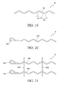
- FIG. 19 is a sectional view of a fifth additional exemplary embodiment of an exemplary structural system.
- FIG. 20 is a sectional view of a first alternative embodiment of the fifth additional exemplary embodiment
- FIG. 21 is a sectional view of a second alternative embodiment of the fifth additional exemplary embodiment.
- FIG. 22 is a sectional view of a sixth additional exemplary embodiment of an exemplary structural system
- FIG. 23 is a sectional view of a first alternative embodiment of the sixth additional exemplary embodiment.
- FIG. 24 is a sectional view of a second alternative embodiment of the sixth additional exemplary embodiment.
- FIG. 25 is a flow chart for an exemplary method for providing a protective coating on a member
- FIG. 26 is a schematic illustration of an exemplary step of submersion in a solution
- FIG. 27 is a schematic illustration of an exemplary drying step
- FIG. 28 is a schematic illustration of an exemplary preparing step
- FIG. 29 is a schematic illustration of exemplary coating equipment
- FIG. 30 is a flow chart for another exemplary method for providing a protective coating on a member.
- FIG. 31 is a graphical illustration of a corrosion rate of the exemplary reinforcing member compared to conventional corrosion rates.
- FIG. 1 illustrates an exemplary structural system 5 for supporting a loading.
- Structural system 5 may be any suitable structural system for supporting load such as, for example, a mechanically stabilized earth (MSE) structural system such as an MSE wall.
- MSE mechanically stabilized earth
- Structural system 5 may also be, for example, a structural system disposed in or near corrosive soil or a structural system disposed in an area exposed to chemical deicing.
- structural system 5 may be a structure disposed at or near a tidal water area or at or near an area having ground water.
- Structural system 5 may be, for example, a structural system disposed on land, a marine structural system, or a coastal structural system.
- Structural system 5 may also be a structure disposed in or a near a non-aggressive soil that may cause corrosion after a relatively long period of time.
- structural system 5 may include one or more structural members 10 , material 15 , one or more reinforcing members 20 , and one or more connection assemblies 25 .
- Structural member 10 may support material 15 .
- Reinforcing member 20 may be disposed in material 15 and may reinforce structural system 5 by supporting structural member 10 .
- Connection assembly 25 may connect structural member 10 and reinforcing member 20 .
- Structural member 10 may be any suitable structural element for supporting load such as, for example, a load associated with material 15 .
- Structural member 10 may be formed from any suitable structural material such as, for example, concrete, steel, polymeric material, composite material, wood, plastics, compacted material such as fill or organic material, or any other suitable material for supporting load.
- structural member 10 may be a prefabricated concrete panel, a cast-in-place reinforced concrete panel, a container containing fill such as a canvas container, or a polymeric or plastic structural member.
- Structural member 10 may be an integral structural member or may be part of a modular structure including a plurality of structural members 10 .
- structural member 10 may be a precast panel and a plurality of structural members 10 may form an MSE panel wall that supports material 15 .
- structural member 10 may be a concrete fascia member.
- structural member 10 may be an integral structural member such as a cast-in-place concrete wall, steel structural member, plastic structural member, slurry wall, hybrid structural member, composite structural member, and/or any other suitable structural member for supporting material 15 .
- structural member 10 may be suitable for retaining earth.
- Material 15 may be any suitable material for use in structural system 5 .
- material 15 may be soil such as compacted soil and/or non-compacted soil.
- Material 15 may include organic material and/or fill material.
- material 15 may include sand, expanded shale, crushed stone, gravel, silt, coal, clay, sand, stones, glass and/or synthetic materials.
- Material 15 may include fine aggregate material and/or coarse aggregate material.
- Material 15 may include any suitable earth or soil material.
- Material 15 may be natural and/or manmade material.
- Material 15 may be unreinforced, natural material and/or reinforced material including cementitious material, plastic mat reinforcement, artificial material such as plastics, additives, and/or any other suitable material for use in structural system 5 .
- Reinforcing member 20 may be any suitable type of member for reinforcing structural system 5 . As illustrated in FIGS. 3-6 , reinforcing member 20 may include a member 30 , a coating 35 , and an aperture 40 . Coating 35 may provide a protective layer for member 30 , and aperture 40 may be disposed at an end portion of reinforcing member 20 and may be used in attaching reinforcing member 20 to connection assembly 25 . Reinforcing member 20 may be embedded in material 15 and may be connected to structural member 10 by connection assembly 25 . Reinforcing member 20 may stabilize structural system 5 by extending back from structural member 10 into material 15 . Reinforcing member 20 may be, for example, a soil reinforcing member.
- Member 30 may be any suitable member for reinforcing structural system 5 .
- member 30 may be a soil reinforcing member.
- Member 30 may include any suitable material for reinforcing structural system 5 .
- member 30 may be a metallic material.
- Member 30 may be a material that is subject to corrosion.
- Member 30 may be, for example, a steel material.
- member 30 may include carbon steel, high strength low alloy steel, low alloy steel, and/or any other suitable type of structural carbon steel.
- Member 30 may also include alloy steel, tool steel, stainless steel, and/or any other suitable type of structural alloy steel.
- Member 30 may include a structural steel such as mild steel including A36 or A50 steel, or high strength steel such as prestressing steel.
- Member 30 may also include structural metals such as, for example, aluminum, iron, tin, copper, nickel, lead, and/or any other metal suitable for use as reinforcing metal.
- Member 30 may be a hybrid material that includes metallic and non-metallic components. It is also contemplated that member 30 may be a nonmetallic material such as a plastic, polymeric, or other suitable nonmetallic material for use as a reinforcing material.
- Member 30 may be galvanized by any suitable galvanization method.
- Member 30 may be aluminized by any suitable aluminization method.
- member 30 may be of any suitable dimensions for reinforcing structural system 5 .
- member 30 may have a length L of between about 6 feet and about 100 feet, between about 8 feet and about 50 feet, or between about 12 feet and about 25 feet.
- member 30 may have a width W of between about 1.5 inches and about 6 inches, between about 2 inches and about 4 inches, or between about 2 inches and about 3 inches.
- member 30 may have a thickness T 1 of between about 1116 inch and about 1.0 inch, between about 3/32 inch and about 3 ⁇ 4 inch, or between about 1 ⁇ 8 inch and about 1 ⁇ 2 inch.
- length L of member 30 may be greater than width W of member 30
- width W of member 30 may be greater than thickness T 1 of member 30
- Width Wand thickness T 1 . of member 30 may be substantially constant along length L of member 30
- width W and/or thickness T 1 of member 30 may vary along length L of member 30 .
- member 30 may be bent at two or more locations along length L.
- Coating 35 may he any suitable coating for providing a protective layer over member 30 .
- Coating 35 may be formed from any suitable material suitable for providing a protective coating that may provide strain compatibility with member 30 .
- coating 35 may be an elastomeric coating.
- coating 35 may include a single component thermoplastic material.
- coating 35 may be a material that is substantially entirely a polyurea material.
- coating 35 may include a two-component thermoplastic material.
- coating 35 may be a two-component aromatic thermoplastic material.
- coating 35 may be a material including polyurethane and/or polyurea.
- coating 35 may be formed from a spray-in-place elastomer such as, for example, a fast-cure spray thermoplastic polyurethane and/or polyurea.
- Coating 35 may be a material having a tensile strength of between about 2,000 psi (lbs/in 2 ) and about 7,000 psi. Additionally for example, coating 35 may have a tensile strength of between about 2,500 psi and about 6,700 psi. Also for example, coating 35 may have a tensile strength of between about 2,000 psi and about 5,000 psi. Further for example, coating 35 may have a tensile strength of between about 4,500 psi and about 5,000 psi.
- a tensile strength of coating 35 may be measured, for example, according to ASTM D412 (American Society for Testing and Materials D412: Standard Test Methods for Vulcanized Rubber and Thermoplastic Elastomers-Tension). Also, for example, coating 35 may have a high shore D hardness allowing for desirable abrasion resistance.
- Coating 35 may be a material having a tear strength (e.g., tear resistance) of between about 500 psi and about 1000 psi. Also for example, coating 35 may have a tear strength of between about 700 psi and about 1000 psi. Additionally for example, coating 35 may have a tear strength of between about 750 psi and about 950 psi. Also for example, coating 35 may have a tear strength of between about 800 psi and about 900 psi. Further for example, coating 35 may have a tear strength of between about 850 psi and about 900 psi. A tear strength of coating 35 may be measured, for example, according to ASTM D624 (American Society for Testing and Materials D624: Standard Test Method for Tear Strength of Conventional Vulcanized Rubber and Thermoplastic Elastomers).
- ASTM D624 American Society for Testing and Materials D624: Standard Test Method for Tear Strength of Conventional Vulcanized Rubber and Thermoplastic Elastomers
- Coating 35 may be a material having an elongation that may provide strain compatibility between member 30 and coating 35 .
- Coating 35 may have an elongation property that is greater than relatively brittle materials such as, for example, epoxy.
- coating 35 may have an elongation property that is greater than other coating materials such as, for example, zinc and aluminum.
- coating 35 may be a material having an elongation of between about 75% and about 700%.
- coating 35 may have an elongation of between about 90% and about 600%.
- coating 35 may have an elongation of between about 300% and about 600%. Additionally for example, coating 35 may have an elongation of between about 450% and about 650%.
- coating 35 may have an elongation of between about 500% and about 600%. Further for example, coating 35 may have an elongation of between about 550% and about 600%. Member 30 may have an elongation that is equal to or less than the elongation of coating 35 , so that strain compatibility may exist between member 30 and coating 35 as described below. For example, member 30 may experience strains of between about 1% and 3%, which may be significantly less than strains that coating 35 may be capable of experiencing, based on its elongation properties. An elongation of coating 35 may be measured, for example, according to ASTM D412 (American Society for Testing and Materials D412: Standard Test Methods for Vulcanized Rubber and Thermoplastic Elastomers—Tension).
- Coating 35 may be a material having a di-electric strength of between about 200 and about 400 V/mil. Also for example, coating 35 may have a di-electric strength of between about 200 and about 350 V/mil. Further for example, coating 35 may have a di-electric strength of between about 240 and about 320 V/mil. Additionally for example, coating 35 may have a di-electric strength of between about 250 and about 300 V/mil. A di-electric strength of coating 35 may be measured, for example, according to ASTM D149 (American Society for Testing and Materials D149: Standard Test Method for Dielectric Breakdown Voltage and Dielectric Strength of Solid Electrical Insulating Materials at Commercial Power Frequencies).
- coating 35 may have any suitable thickness for providing a protective coating for member 30 .
- coating 35 may have a thickness T 2 of between about 10 mils (e.g., about 0.254 mm) and about 100 mils (e.g., about 2.54 mm).
- coating 35 may have thickness T 2 of between about 20 mils (e.g., about 0.508 mm) and about 80 mils (e.g., about 2.032 mm).
- coating 35 may have thickness T 2 of between about 20 mils (e.g., about 0.508 mm) and about 60 mils (e.g., about 1.524 mm).
- coating 35 may have thickness T 2 of between about 30 mils (e.g., about 0.762 mm) and about 50 mils (e.g., about 1.27 mm). Also for example, coating 35 may have thickness T 2 of between about 40 mils (e.g., about 1.016 mm) and about 60 mils (e.g., about 1.524 mm). Thickness T 2 of coating 35 may be a substantially uniform thickness. Also, thickness T 2 of coating 35 may vary along length L and/or width W of member 30 . For example, thickness T 2 of coating 35 may be relatively thicker at an end portion 42 (e.g., as illustrated in FIGS.
- thickness T 2 may be thicker at end portion 42 (which may be a first end portion) relative to other portions of reinforcing member 20 , and thickness T 2 may decrease in thickness along a length of reinforcing member 20 in a direction moving away from end portion 42 .
- Thickness T 1 of member 30 may be, for example, between about 2 times and about 125 times greater than thickness T 2 of coating 35 . Also for example, thickness T 1 may be, for example, between about 5 times and about 100 times greater than thickness T 2 , or between about 10 times and about 50 times greater than thickness T 2 . It is also contemplated that thickness T 1 may be, for example, about the same size as thickness T 2 , or that thickness T 1 may be, for example, less than thickness T 2 .
- Coating 35 may include a material similar to LINE-X protective coatings available from LINE-X, LLC. Also, for example, coating 35 may include a material similar to Speedliner® available from Bearcat Industries, L.P. Further, for example, coating 35 may include a material similar to Rhino ExtremeTM 11-50 GT available from Rhino Linings Corporation.
- Coating 35 may be a protective coating that substantially prevents corrosion of member 30 .
- Coating 35 may be applied to substantially all surfaces of member 30 and may thereby cover substantially the entire member 30 .
- Coating 35 may thereby completely encapsulate member 30 .
- Coating 35 may thereby provide a protective coaling for substantially all surfaces of member 30 . Accordingly, design thickness T 1 of member 30 may be reduced because substantially no additional material to account for corrosion over a service life of reinforcing member 20 is appropriate. Accordingly, coating 35 may allow for a decreased thickness T 1 of member 30 to be used. It is also contemplated that only some surfaces of member 30 may be coated with coating 35 so that member 30 may be partially encapsulated by coating 35 .
- member 30 maybe bent at two or more locations along length L and/or width W so that reinforcing member 20 includes a plurality of curved segments 45 and substantially straight tangential segments 50 .
- Curved segments 45 may allow reinforcing member 20 to develop increased resistance with a portion of material 15 disposed between crest lines 55 and 60 .
- Crest lines 55 and 60 may be disposed between outermost surfaces of curved segments 45 as illustrated in FIG. 7 .
- Portion 65 of material 15 disposed between crest lines 55 and 60 may be restrained in a load direction D and act integrally with reinforcing member 20 .
- a friction force between portion 65 and reinforcing member 20 may be increased, because an apparent surface contact area and coefficient of friction between the particles of material 15 disposed in portion 65 and reinforcing member 20 are increased, based on the configuration of portion 65 having a height H. Further, coating 35 may have a relatively rough surface that may increase frictional resistance between material 15 and reinforcing member 20 , increasing a resistance of reinforcing member 20 from pull-out from material 15 .
- reinforcing member 20 may be an elongated inextensible element that may be shaped into a nonlinear element so that axial tension may be resisted by flexure in portions of reinforcing member 20 instead of direct linear stress.
- reinforcing member 20 may have a non-linear shape such as, for example, a sine curve, a series of zigzags, a series of tangents and curves, and/or a spiral in any plane. As load is applied to reinforcing member 20 in direction D, reinforcing member 20 may elongate as a function of a configuration-material relationship.
- reinforcing member 20 may transfer the load into the surrounding portions of material 15 by both friction and passive soil resistance (e.g., the passive resistance being a function of the geometry of reinforcing member 20 ). After elongating, reinforcing member 20 may remain at a desirable stress.
- connection assembly 25 may be any suitable connection for making a mechanical connection between structural member 10 and reinforcing member 20 .
- Connection assembly 25 may include a member 70 and a fastener 75 .
- Fastener 75 may mechanically fasten reinforcing member 20 to member 70 .
- Member 70 may be any suitable member for connecting structural member 10 and reinforcing member 20 .
- Member 70 may be formed from a material that is similar to member 30 of reinforcing member 20 .
- Member 70 may be coated with a coating 80 that may be similar to coating 35 of reinforcing member 20 .
- Coating 80 may cover some or substantially the entire member 70 .
- Member 70 may be attached to structural member 10 by any suitable method. For example, member 70 may be mechanically attached to structural member 10 or may be inserted into structural member 10 prior to structural member 10 being cast (e.g., when structural member 10 is a cast member).
- member 70 may be coated with coating 80 and embedded in structural member 10 (e.g., that is a precast concrete member or cast-in-place concrete member) prior to hardening of structural member 10 .
- member 70 may include apertures that may be aligned with aperture 40 of reinforcing member 20 .
- Fastener 75 may be any suitable mechanical fastener for fastening member 70 and reinforcing member 20 .
- fastener 75 may be a threaded bolt assembly including a threaded nut and a threaded bolt that may be inserted through aperture 40 of reinforcing member 20 and apertures of member 70 (e.g., as illustrated in FIG. 8 ).
- Fastener 75 may be coated with a coating 85 that may be similar to coating 35 .
- Coating 85 may cover some or substantially the entire fastener 75 .
- coatings 80 and 85 may cover substantially all surfaces of connection assembly 25 . As illustrated in FIGS.
- fastener 75 may provide a mechanical connection between member 70 and reinforcing member 20 by utilizing apertures of member 70 and aperture 40 of reinforcing member 20 .
- Fastener 70 may also be any other suitable fastener such as, for example, a clamping device. It is also contemplated that member 70 and reinforcing member 20 may be attached by adhesive, welding, or any other suitable method for attaching structural members.
- thickness T 2 of coating 35 may be relatively thicker at end portion 42 of reinforcing member 20 disposed at or near connection assembly 25 , as compared to other portions of reinforcing member 20 .
- Coatings 80 and 85 may be of a similar thickness as thickness T 2 at end portion 42 of reinforcing member 20 .
- end portion 42 and connection assembly 25 may be located at a zone of maximum stress of structural system 5 (e.g., along a boundary between an active and resistant zone in the case where structural system 5 is an MSE wall)
- coatings 35 , 80 , and 85 may have relatively greater thicknesses at this location of relatively greater stress.
- thickness T 2 may decrease in thickness along a length of reinforcing member 20 in a direction moving away from end portion 42 and connection assembly 25 .
- FIGS. 10 and 11 illustrate a first additional exemplary embodiment of the disclosed structural system.
- Structural system 5 a may include one or more structural members 10 a , material 15 a , one or more reinforcing members 20 a , and one or more connection assemblies 25 a .
- Structural members 10 a may support material 15 a .
- Reinforcing members 20 a may be disposed in material 15 a , which may be similar to material 15 , and may reinforce structural system 5 a by supporting structural member 10 a .
- Reinforcing members 20 a may be similar to reinforcing member 20 .
- Connection assembly 25 a may be similar to connection assembly 25 and may connect structural member 10 a and reinforcing member 20 a.
- structural members 10 a may form a block fascia unit 28 a .
- Structural members 10 a may be similar to structural members 10 .
- Reinforcing members 20 a may be attached to some structural members 10 a via connection assemblies 25 a . It is also contemplated that reinforcing members 25 a may be attached to substantially all structural members 10 a via connection assemblies 25 a .
- Structural members 10 a may be any suitable modular structural system for supporting material 15 a .
- structural members 10 a may be reinforced precast concrete panels.
- structural members 10 a may be of substantially similar configurations and/or variable configurations to facilitate assembly of block fascia unit 28 a.
- FIG. 12 illustrates a second additional exemplary embodiment of the disclosed structural system.
- Structural system 5 b may include material 15 b and one or more reinforcing members 20 b .
- Reinforcing members 20 b may be disposed in material 15 b and may support material 15 b , which may be similar to material 15 .
- Reinforcing members 20 b may be similar to reinforcing member 20 .
- reinforcing members 20 b may support material 15 b by being disposed in material 15 b , without inclusion of additional structural members and connection assemblies.
- structural system 5 b may include fascia structural members and/or connection assemblies.
- FIGS. 13-15 illustrate a third additional exemplary embodiment of the disclosed structural system.
- Structural system 5 c may include one or more structural members (not shown, may be similar to structural member 10 ), material (not shown, may be similar to material 15 ), one or more reinforcing members 20 c , and one or more connection assemblies (not shown, may be similar to connection assembly 25 ).
- reinforcing member 20 c may include members 20 c 1 and 20 c 2 , that may be formed from material similar to member 30 .
- Members 20 c 1 and 20 c 2 may be coated similarly to member 30 , with a coating 35 c that may be similar to coating 35 .
- Reinforcing member 20 c may be a grid-like or built-up reinforcement assembly.
- reinforcing member 20 c may be welded wire reinforcement, and members 20 c 1 and 20 c 2 may be reinforcing bars.
- FIGS. 16-18 illustrate a fourth additional exemplary embodiment of the disclosed structural system.
- Structural system 5 d may include one or more structural members (not shown, may be similar to structural member 10 ), material (not shown, may be similar to material 15 ), one or more reinforcing members 20 d , and one or more connection assemblies (not shown, maybe similar to connection assembly 25 ).
- reinforcing member 20 d may include a member 30 d that may be formed from material similar to member 30 .
- Member 30 d may be coated similarly to member 30 , with a coating 35 d that may be similar to coating 35 .
- Reinforcing member 20 d may be a substantially flat member having substantially no bends or curves.
- reinforcing member 20 d may be a substantially flat plate member.
- FIG. 19 illustrates a fifth additional exemplary embodiment of the disclosed structural system.
- Structural system 5 e may include one or more structural members (not shown, may be similar to structural member 10 ), material (not shown, may be similar to material 15 ), one or more reinforcing members 20 e , and one or more connection assemblies (not shown, may be similar to connection assembly 25 ).
- Reinforcing member 20 e may be similar to reinforcing member 20 .
- Reinforcing member 20 e may include a plurality of bent segments 45 e and substantially straight tangential segments 50 e .
- Bent segments 45 e may be relatively sharp bends in reinforcing member 20 e .
- the plurality of bent segments 45 e and substantially straight tangential segments 50 e may develop increased resistance as discussed above with reference to curved segments 45 and tangential segments 50 .
- FIG. 20 illustrates a first alternative embodiment of the fifth exemplary embodiment.
- a reinforcing member 20 e 1 is looped to form an aperture 22 e .
- Aperture 22 e may serve a purpose that is similar to aperture 40 , described above.
- FIG. 21 illustrates a second alternative embodiment of the fifth exemplary embodiment.
- reinforcing members 20 e 1 are looped to form apertures 22 e .
- reinforcing members 20 e 1 may be attached to transverse reinforcing members 20 e 2 to form a grid pattern such as, for example, a welded wire mat.
- FIG. 22 illustrates a sixth additional exemplary embodiment of the disclosed structural system.
- Structural system 5 f may include one or more structural members 10 f (may be similar structural member 10 ), material 15 f (may be similar to material 15 ), one or more reinforcing members 20 f (may be similar to reinforcing member 20 ), and one or more connection assemblies 25 f.
- Connection assembly 25 f may be formed from similar materials as connection assembly 25 and may be coated similarly to connection assembly 25 . As illustrated in FIG. 22 , connection assembly 25 f may include a connector that is partially embedded in structural member 10 f and that has a mechanical fastener (e.g., a pin or a bolt) that extends through the embedded connector and reinforcing member 20 f , thereby forming a connection.
- a mechanical fastener e.g., a pin or a bolt
- FIG. 23 illustrates a first alternative embodiment of the sixth exemplary embodiment.
- reinforcing member 20 f may extend through structural member 10 f .
- Connection assembly 25 f 1 may be a fastener such as a pin or bolt that extends through an aperture in reinforcing member 20 f and along an outer surface of structural member 10 f , thereby forming a connection.
- Connection assembly 25 f 1 may be formed from similar materials as connection assembly 25 and may be coated similarly to connection assembly 25
- FIG. 24 illustrates a second alternative embodiment of the sixth exemplary embodiment.
- Connection assembly 25 f 2 may be similar to connection assembly 25 f 1 and may be disposed inside of structural member 10 f.
- the exemplary disclosed system and method may be used in any application involving providing a protective coating of reinforcement material.
- the disclosed structure and method may be used in applications involving construction and/or structural systems having metallic reinforcement that is exposed to corrosion.
- the exemplary disclosed system may be used in a mechanically stabilized earth (MSE) structural system such as an MSE wall.
- MSE mechanically stabilized earth
- the exemplary disclosed system and method may be used in areas having corrosive soil, exposed to chemical deicing, and/or disposed at or near a tidal water areas or areas having ground water.
- the exemplary disclosed system may be used in a structural system disposed on land, a marine structural system, or a coastal structural system.
- the exemplary disclosed system may be used in a structural system disposed in or near a non-aggressive soil that may cause corrosion after a relatively long period of time.
- FIG. 25 illustrates an exemplary disclosed method for providing a protective coating on a member.
- Structural system 5 illustrated in FIGS. 1-9 , will be used as an exemplary embodiment to illustrate the exemplary disclosed construction method, though any of the disclosed exemplary embodiments may be used to illustrate the exemplary method for providing a protective coating on a member.
- the exemplary disclosed method for providing a protective coating on a member may be used, for example, in conjunction with any of the exemplary embodiments described above.
- member 30 is configured.
- member 30 may be shaped in a desired form as illustrated, e.g., in FIGS. 3 and 4 .
- member 30 may be bent at two or more locations along a length of member 30 , thereby bending member 30 at a plurality of locations along the length of member 30 .
- Member 30 may also be punched, for example, to provide aperture 40 .
- member 30 may be galvanized and/or aluminized by any suitable method. For example, steel strips or wires may be configured into a final geometry, then hot-dip galvanized in a bath of zinc to configure member 30 .
- member 30 may be configured in any other suitable manner.
- a steel coil may be dipped in a bath, slit, and then configured into a desired shape for member 30 (e.g., shaped and punched) as illustrated in FIGS. 3 and 4 .
- a sheet of steel coil may be dipped in a bath of pure aluminum, the steel coil may be slit, and the resulting steel strips (e.g., Aluminized Steel Type 2) may be configured into member 30 having a final, desired geometry.
- Members of reinforcing members 20 a , 20 b , 20 c , 20 d , 20 e , and 20 f may be similarly configured according to step 200 .
- member 30 is submersed in a solution.
- member 30 may be submersed in a material 206 contained in a housing 207 .
- Material 206 may be any suitable material for preparing member 30 for adhesion by removing scale and/or substantially preventing loss of a base material of member 30 .
- material 206 may be a pickling solution.
- material 206 may include soluble organic and/or inorganic phosphorous-sulfur compounds.
- Member 30 may be partially or entirely substantially submersed in material 206 .
- Members of reinforcing members 20 a , 20 b , 20 c , 20 d , 20 e , and 20 f may be similarly submersed according to step 205 .
- member 30 is dried.
- Member 30 may be dried by any suitable method such as, for example, being dried by using a heating device, being dried by using a drying device, or being dried over time in ambient conditions. For example, as illustrated in FIG. 27 , member 30 may be dried by using an infrared heater 211 to reduce drying time.
- Members of reinforcing members 20 a , 20 b , 20 c , 20 d , 20 e , and 20 f may be similarly dried according to step 210 .
- member 30 is prepared for coating.
- member 30 may be suitably placed for coating.
- member 30 may be laid out or hung for a coating method such as, for example, spraying.
- member 30 may be hung or suitably placed for coating.
- member 30 may be prepared for coating by being hung from a device 216 such as, for example, a mechanical clamp, a device having a projection for receiving aperture 40 , or any other suitable device on which member 30 may be placed in preparation for coating (e.g., a mount or other device for supporting member 30 from below).
- a device 216 such as, for example, a mechanical clamp, a device having a projection for receiving aperture 40 , or any other suitable device on which member 30 may be placed in preparation for coating (e.g., a mount or other device for supporting member 30 from below).
- Members of reinforcing members 20 a , 20 b , 20 c , 20 d , 20 e , and 20 f may be similarly prepared according to step 215 .
- coating equipment is connected to stored material for coating.
- coating equipment 221 may be connected to stored material housing 222 that may be any suitable housing for storing a coating material and may be a pressurized container.
- coating equipment 221 may include a passageway 223 and a nozzle assembly 224 , Passageway 223 may fluidly connect stored material housing 222 to nozzle assembly 224 .
- Coating material 226 contained in housing 222 may thereby be transported from housing 222 to nozzle assembly 224 via passageway 223 .
- Coating equipment 221 and housing 222 may store and transfer coating material 226 under pressure.
- Passageway 223 may be any suitable passageway for transferring coating material 226 such as, for example, a flexible hose and/or a heated hose.
- Nozzle assembly 224 may be any suitable device for placing coating material such as, for example, a spray nozzle for placing a pressurized coating material.
- coating equipment 221 and housing 222 may provide substantially precise fluid pressure for coating material 226 suitable for providing coating 35 having desired coating mix, thickness, and polymerization.
- coating equipment 221 may be a multiple component spray machine that internally mixes polyurethane.
- Coating material 226 includes materials corresponding to the materials described above for coating 35 (e.g., applying coating material 226 to member 30 provides coating 35 on member 30 ). Similar preparations may be made, e.g., for coatings 35 c , 35 d , 80 , and 85 .
- nozzle assembly 224 a fluid pressure of coating material 226 , and a temperature of coating material 226 are prepared for application.
- An operator may operate coating equipment 221 and housing 222 to bring coating material 226 to a desired fluid pressure and temperature.
- An operator may also prepare nozzle assembly 224 to provide coating 35 having desired coating mix, thickness, and polymerization.
- Coating material 226 may be heated, for example, to between about 100 degrees and about 160 degrees, or to between about 120 degrees and about 140 degrees. Similar preparations may be made, e.g., for coatings 35 c , 35 d , 80 , and 85 .
- step 230 member 30 is sprayed using coating equipment 221 .
- Nozzle assembly 224 may mix components of coating material 226 at or near a tip of nozzle assembly 224 , and dispense material 226 at high pressure to form coating 35 .
- a desired coating may thereby be provided (e.g., as described above for coating 35 provided on member 30 ).
- coating equipment 221 may be used to spray-coat member 30 with coating material 226 (e.g., elastomeric material) to provide coating 35 .
- Reinforcing member 20 may be allowed to cure if appropriate.
- coating material 226 may dry rapidly to form coating 35 (e.g., dry in up to 5 or 10 seconds).
- Reinforcing members 20 a , 20 b , 20 c , 20 d , 20 e , and 20 f may be similarly prepared according to step 230 .
- step 235 touchup work is performed if appropriate to facilitate encapsulation of reinforcing member 20 .
- additional coating material 226 may be applied to member 30 to facilitate substantially all surfaces of member 30 being sufficiently covered with coating 35 .
- Reinforcing members 20 a , 20 b , 20 c , 20 d , 20 e , and 20 f may be similarly touched up according to step 235 .
- Members of reinforcing members 20 a , 20 b , 20 c , 20 d , 20 e , and 20 f may thereby be completely or partially encapsulated by their respective coatings.
- reinforcing member 20 is allowed to dry.
- reinforcing member 20 may be allowed to become substantially entirely dry.
- Reinforcing members 20 a , 20 b , 20 c , 20 d , 20 e , and 20 f may be similarly allowed to dry according to step 240 .
- an alloy layer between the coating and the member may not form (e.g., as in the case of zinc and aluminum coatings, in which case an alloy layer does form).
- Reinforcing members 20 , 20 a , 20 b , 20 c , 20 d , 20 e , and 20 f are disposed in material 15 (and respective material per the above exemplary embodiments, e.g., material 15 a ).
- reinforcing members 20 are connected to structural members 10 via connection assemblies 25 of structural system 5 (as well as other exemplary embodiments as set forth above, e.g., structural systems 5 a , 5 c , 5 d , and/or 5 f ).
- the exemplary disclosed reinforcing members resist load in load direction D as illustrated in FIG. 7 .
- reinforcing member 20 resists load in load direction D (e.g., as illustrated in FIG. 7 ), reinforcing member 20 transfers the load into the surrounding portions of material 15 by both friction and passive resistance (e.g., passive soil resistance) as described above. Also, as described above, reinforcing member 20 elongates based on its non-linear shape as load is resisted in load direction D, providing additional elasticity that allows portion 65 of material 15 to develop increased shear strength, which reduces the load in reinforcing member 20 .
- Reinforcing members 20 a , 20 b , 20 c , 20 e , 20 e 1 , and 20 f may elongate similarly.
- elongation properties of coating 35 provide it with strain compatibility with member 30 .
- member 30 is strained under load, coating 35 undergoes similar strain without fracture due to the elongation properties described above. Accordingly, reinforcing member 20 undergoes strain with strain compatibility between member 30 and coating 35 .
- Reinforcing members 20 a , 20 b , 20 c , 20 d , 20 e , 20 e 1 , and 20 f may experience similar strain compatibility.
- coating 35 protects member 30 from corrosion.
- An initial cross section of member 30 is thereby maintained over the design life of structural system 5 .
- thickness of member 30 remains substantially constant over the design life of structural system 5 , which maintains substantially constant strain and stress distribution across member 30 , which may keep reinforcing member 20 substantially uniformly extensible throughout a service life of structural system 5 .
- Coated members of reinforcing members 20 a , 20 b , 20 c , 20 d , 20 e , 20 e 1 , and 20 f similarly maintain their initial cross sections.
- the coated exemplary connection assemblies described above similarly maintain their initial cross sections.
- FIG. 30 illustrates another exemplary disclosed method for providing a protective coating on a member, which may provide a protective coating using any suitable techniques.
- a member is configured.
- the member may be configured in a similar manner as described above in step 200 , or by any other suitable technique for configuring a reinforcing member.
- a member is prepared for coating.
- the member maybe prepared in a similar manner as described above in step 215 , or by any other suitable technique for preparing a reinforcing member for coating.
- the member may be coated.
- the member may be coated in a similar manner as described above in step 230 , or by any other suitable technique for coating a member such as, for example, by mechanically applying a coating or dipping the member into a coating material.
- coating equipment 221 may include an apparatus for rolling a coating material onto a member to provide coating 35 on the member.
- coating equipment 221 may include equipment that allows for a member to be coated by dipping the member into a coating material, thereby providing coating 35 onto the member.
- the member may be seamlessly encapsulated by the coating.
- corrosion and metal loss may be a function of surface irregularity and differential aeration mechanisms on the member.
- the coating encapsulates the member, the member may not be exposed to a material such as soil, which may substantially prevent surface irregularities, impurities in the material of the encapsulated member, and differential aeration that lead to material loss (e.g., micro-cells and electrical potential, which may lead to corrosion, are no longer present).
- material loss e.g., micro-cells and electrical potential, which may lead to corrosion, are no longer present.
- the member when the member is encapsulated by the coating, macro-cells that may develop between the exemplary structural member and an end portion of the exemplary reinforcing member are no longer connected by a conduit (e.g., a steel conduit in the case in which the exemplary reinforcing member is metal such as steel).
- the encapsulated member thereby does not have a higher potential between pH differences in the material of the exemplary structural system (e.g., between a concrete fascia and soil backfill, when the exemplary structural system is an MSE wall).
- the coating electrically isolates the encapsulated member.
- coating the member e.g., member 30 or any other exemplary member disclosed above
- FIG. 31 is a graph illustrating a corrosion rate of the exemplary reinforcing members compared to conventional corrosion rates.
- FIG. 31 illustrates how the thickness of conventional reinforcing members (e.g., as represented in the graph by Galvanized Steel and ALT2 Steel, as calculated according to design standards of the American Association of State Highway and Transportation Officials) decrease over a lifetime of conventional structures due to corrosion.
- FIG. 31 shows how an example of the exemplary disclosed reinforcing members (e.g., elastomeric coating steel) experiences little or substantially no decrease in thickness due to corrosion.
- the exemplary disclosed system and method may provide a protective coating that substantially prevents corrosion of reinforcing members over the service life of a structure.
- the exemplary disclosed system may provide a method for delaying an onset of corrosion, allowing the use of relatively thin metallic elements as reinforcement for the design life of a structure, without using increased thicknesses of reinforcement to account for corrosion.
- the exemplary disclosed system may provide connections between reinforcing members and fascia structural members that are corrosion-resistant. Further for example, the exemplary disclosed system may provide increased abrasion resistance for reinforcing members during handling and shipping.
Abstract
Description
Claims (20)
Priority Applications (1)
| Application Number | Priority Date | Filing Date | Title |
|---|---|---|---|
| US15/400,402 US10081927B2 (en) | 2015-01-12 | 2017-01-06 | System and method for protective coating of reinforcement |
Applications Claiming Priority (3)
| Application Number | Priority Date | Filing Date | Title |
|---|---|---|---|
| US201562125054P | 2015-01-12 | 2015-01-12 | |
| US14/671,421 US9574318B2 (en) | 2015-01-12 | 2015-03-27 | System and method for protective coating of reinforcement |
| US15/400,402 US10081927B2 (en) | 2015-01-12 | 2017-01-06 | System and method for protective coating of reinforcement |
Related Parent Applications (1)
| Application Number | Title | Priority Date | Filing Date |
|---|---|---|---|
| US14/671,421 Continuation US9574318B2 (en) | 2015-01-12 | 2015-03-27 | System and method for protective coating of reinforcement |
Publications (2)
| Publication Number | Publication Date |
|---|---|
| US20170183841A1 US20170183841A1 (en) | 2017-06-29 |
| US10081927B2 true US10081927B2 (en) | 2018-09-25 |
Family
ID=56367136
Family Applications (2)
| Application Number | Title | Priority Date | Filing Date |
|---|---|---|---|
| US14/671,421 Expired - Fee Related US9574318B2 (en) | 2015-01-12 | 2015-03-27 | System and method for protective coating of reinforcement |
| US15/400,402 Expired - Fee Related US10081927B2 (en) | 2015-01-12 | 2017-01-06 | System and method for protective coating of reinforcement |
Family Applications Before (1)
| Application Number | Title | Priority Date | Filing Date |
|---|---|---|---|
| US14/671,421 Expired - Fee Related US9574318B2 (en) | 2015-01-12 | 2015-03-27 | System and method for protective coating of reinforcement |
Country Status (3)
| Country | Link |
|---|---|
| US (2) | US9574318B2 (en) |
| CA (1) | CA2971117C (en) |
| WO (1) | WO2016115119A1 (en) |
Families Citing this family (5)
| Publication number | Priority date | Publication date | Assignee | Title |
|---|---|---|---|---|
| JP6755909B2 (en) * | 2018-08-24 | 2020-09-16 | 日亜鋼業株式会社 | Manufacturing method and manufacturing system for galvanized deformed steel bars |
| NL2022034B1 (en) | 2018-11-20 | 2020-07-10 | Jetmix B V | A metal construction tie |
| US11174615B2 (en) * | 2019-05-07 | 2021-11-16 | E.C. Manufacturing, LLC | Landscaping walls, systems and methods |
| US20210332538A1 (en) * | 2020-04-22 | 2021-10-28 | Truetech Bridge, Llc | Transparent or translucent panel systems, related systems, and related methods |
| US20210332549A1 (en) * | 2020-04-23 | 2021-10-28 | The Taylor IP Group | Soil reinforcing element and method of manufacturing |
Citations (13)
| Publication number | Priority date | Publication date | Assignee | Title |
|---|---|---|---|---|
| US4116010A (en) | 1975-09-26 | 1978-09-26 | Henri Vidal | Stabilized earth structures |
| US4124983A (en) | 1976-12-27 | 1978-11-14 | Schnabel Foundation Company | Corrosion protected earth tieback |
| US5249898A (en) | 1991-04-17 | 1993-10-05 | Bayer Aktiengesellschaft | Composite anchor incorporating a water-curing polymer composition |
| US5472296A (en) | 1992-08-20 | 1995-12-05 | Dyckerhoff & Widmann Aktiengesellschaft | Corrosion protected support element for a soil anchor or a rock anchor, a pressure pile or the like |
| US5797706A (en) | 1993-06-24 | 1998-08-25 | Societe Civile Des Brevets Henri Vidal | Earth structures |
| US6313254B1 (en) | 1996-09-23 | 2001-11-06 | Cardiac Crc Nominees Pty Ltd | Polysiloxane-containing polyurethane elastomeric compositions |
| US20030185634A1 (en) | 2000-02-22 | 2003-10-02 | Babcock John W. | Synthetic deformed bars and retaining walls |
| US6719487B2 (en) | 2000-12-20 | 2004-04-13 | Kankyo Kogaku Co., Ltd. | Structural unit for construction, construction of said structural units, and method for the preparation of said structural units and said construction |
| US7270502B2 (en) | 2005-01-19 | 2007-09-18 | Richard Brown | Stabilized earth structure reinforcing elements |
| US8079782B1 (en) | 2008-05-16 | 2011-12-20 | Hilfiker William K | Semi-extensible steel soil reinforcements for mechanically stabilized embankments |
| US20120114963A1 (en) | 2010-11-10 | 2012-05-10 | Mckittrick David | Protective coatings for controlled corrosion resistance |
| US20130035466A1 (en) | 2010-03-05 | 2013-02-07 | Recticel Automobilsysteme Gmbh | Method for producing a skin layer of a flexible, elastomeric, thermoset, phase-separated polyurethane material |
| US8685303B2 (en) | 2003-12-17 | 2014-04-01 | Terrasimco Inc. | Coated mining bolt |
-
2015
- 2015-03-27 US US14/671,421 patent/US9574318B2/en not_active Expired - Fee Related
-
2016
- 2016-01-12 CA CA2971117A patent/CA2971117C/en active Active
- 2016-01-12 WO PCT/US2016/013028 patent/WO2016115119A1/en active Application Filing
-
2017
- 2017-01-06 US US15/400,402 patent/US10081927B2/en not_active Expired - Fee Related
Patent Citations (14)
| Publication number | Priority date | Publication date | Assignee | Title |
|---|---|---|---|---|
| US4116010A (en) | 1975-09-26 | 1978-09-26 | Henri Vidal | Stabilized earth structures |
| US4124983A (en) | 1976-12-27 | 1978-11-14 | Schnabel Foundation Company | Corrosion protected earth tieback |
| US5249898A (en) | 1991-04-17 | 1993-10-05 | Bayer Aktiengesellschaft | Composite anchor incorporating a water-curing polymer composition |
| US5472296A (en) | 1992-08-20 | 1995-12-05 | Dyckerhoff & Widmann Aktiengesellschaft | Corrosion protected support element for a soil anchor or a rock anchor, a pressure pile or the like |
| US5797706A (en) | 1993-06-24 | 1998-08-25 | Societe Civile Des Brevets Henri Vidal | Earth structures |
| US6313254B1 (en) | 1996-09-23 | 2001-11-06 | Cardiac Crc Nominees Pty Ltd | Polysiloxane-containing polyurethane elastomeric compositions |
| US20030185634A1 (en) | 2000-02-22 | 2003-10-02 | Babcock John W. | Synthetic deformed bars and retaining walls |
| US6719487B2 (en) | 2000-12-20 | 2004-04-13 | Kankyo Kogaku Co., Ltd. | Structural unit for construction, construction of said structural units, and method for the preparation of said structural units and said construction |
| US8685303B2 (en) | 2003-12-17 | 2014-04-01 | Terrasimco Inc. | Coated mining bolt |
| US7270502B2 (en) | 2005-01-19 | 2007-09-18 | Richard Brown | Stabilized earth structure reinforcing elements |
| US8079782B1 (en) | 2008-05-16 | 2011-12-20 | Hilfiker William K | Semi-extensible steel soil reinforcements for mechanically stabilized embankments |
| US20130035466A1 (en) | 2010-03-05 | 2013-02-07 | Recticel Automobilsysteme Gmbh | Method for producing a skin layer of a flexible, elastomeric, thermoset, phase-separated polyurethane material |
| US20120114963A1 (en) | 2010-11-10 | 2012-05-10 | Mckittrick David | Protective coatings for controlled corrosion resistance |
| US8927112B2 (en) | 2010-11-10 | 2015-01-06 | David McKittrick | Protective coatings for controlled corrosion resistance |
Non-Patent Citations (11)
| Title |
|---|
| "AASHTO LRFD Bridge Design Specifications," excerpt from Section 11: Walls, Abutments, and Piers by the American Association of State Highway and Transportation Officials, 2012 (14 pages). |
| "K-Stiffness Method", FHWA NHI-10-025 MSE Walls and RSS-vol. II, Nov. 2009 excerpt, (1 page). |
| "Line-X Spray-On Truck Bedliners," product information dated Dec. 14, 2006, retrieved from https://web.archive.org/web/20061214112649/http://linex.com/. |
| "Reduced Zinc Loss Rate for Design of MSE Structures," A White Paper by the Association for Metallically Stabilized Earth, pp. 7-10, May 2006 (4 pages). |
| "Speedliner," product information dated Dec. 21, 1997, retrieved from https://web.archive.org/web/19971221171358/http://speedliner.com/qual.htm. |
| "K-Stiffness Method", FHWA NHI-10-025 MSE Walls and RSS—vol. II, Nov. 2009 excerpt, (1 page). |
| BASF Technical Product Data, Elastocoat AC 72376R Resin, dated Aug. 15, 2012, retrieved from http:///www.polyurethanes.basf.us/files/pdf/Elastocoat%20AC%2072376R72375T72375TTechnical%20Product%Data.pdf (2 pages). |
| Daggett, Susan. "A Guide to Selection of methacrylate, urethane and epoxy adhesives." Composites World website, dated Apr. 1, 2004, retrieved from http://compositesworld.com/articles/a-quide-to-selection-of-methacrylate-urethane-and-epoxy-adhesives. (6 pages). |
| International Search Report and Written Opinion for PCT/US2016/013028, dated Feb. 23, 2016 (8 pages). |
| Rhino Linings World-Class Protection-Coatings for Bridge Preservation: "Protective Lining Over Steel and Concrete," product information, Rhino Linings Corporation 2014, retrieved from www.rhinoliningsindustrial.com (2 pages). |
| Rhino Linings World-Class Protection—Coatings for Bridge Preservation: "Protective Lining Over Steel and Concrete," product information, Rhino Linings Corporation 2014, retrieved from www.rhinoliningsindustrial.com (2 pages). |
Also Published As
| Publication number | Publication date |
|---|---|
| CA2971117A1 (en) | 2016-07-21 |
| US9574318B2 (en) | 2017-02-21 |
| US20170183841A1 (en) | 2017-06-29 |
| WO2016115119A1 (en) | 2016-07-21 |
| CA2971117C (en) | 2020-08-04 |
| US20160201288A1 (en) | 2016-07-14 |
Similar Documents
| Publication | Publication Date | Title |
|---|---|---|
| US10081927B2 (en) | System and method for protective coating of reinforcement | |
| US9758968B2 (en) | Method for building prestressed concrete structures by means of profiles consisting of a shape-memory alloy, and structure produced using said method | |
| US8960612B2 (en) | Non-metallic support stanchion | |
| JP7326260B2 (en) | sticker | |
| US20160060889A1 (en) | Repair and reinforcement of utility poles | |
| AU2006328239A1 (en) | Reinforcement method and reinforcement structure of a corrugated steel plate structure | |
| KR101260537B1 (en) | Method for reinforcing a metal tubular structure | |
| US20190049053A1 (en) | Corrugated metal pipe repair system and method | |
| CN106195463A (en) | A kind of pressure pipeline of water-tight corrosion-proof | |
| JP4264095B2 (en) | Manhole reinforcement structure | |
| US20100038019A1 (en) | Process for obtaining pipes and joints from a polymer composite | |
| US9290956B1 (en) | Structure reinforcement system and method | |
| US6331242B1 (en) | Anodic encasement corrosion protection system for underground storage tanks, and metallic components thereof | |
| US20230058041A1 (en) | Cable racks for reduced stress and increased load capacity | |
| KR200408009Y1 (en) | Thread Bar for Anchor Pile | |
| CN106945369A (en) | A kind of heavy antisepsis height memory woven fabric armor | |
| CN207960126U (en) | A kind of iron tower component | |
| KR20060108348A (en) | Supplement belt for the pillar structure | |
| CN220058660U (en) | Corrosion-resistant heavy-load anti-slip terrace | |
| CN114294016B (en) | Reinforcing device for cable tunnel, manufacturing method and cable tunnel assembly | |
| KR101493190B1 (en) | Reinforcement method using reinforced bar | |
| KR101639704B1 (en) | Apparatus for preventing corrosion of transmission or electrical distribution steel towers and steel structure for substation | |
| CN113308994A (en) | Cable body and gas phase corrosion inhibition parallel steel wire inhaul cable | |
| KR200389246Y1 (en) | Supplement belt for the pillar structure | |
| Efaz et al. | Scope and application of fusion bonded epoxy coated rebars” as a viable solution for corrosion problems in Bangladesh: a review” |
Legal Events
| Date | Code | Title | Description |
|---|---|---|---|
| AS | Assignment |
Owner name: SINE WALL, LLC, NORTH CAROLINA Free format text: ASSIGNMENT OF ASSIGNORS INTEREST;ASSIGNORS:BRODOWSKI, DAVID M.;BRERETON, TIMOTHY J.;ERANA, MICHAEL F.;REEL/FRAME:041100/0657 Effective date: 20150327 Owner name: INVENTURE CIVIL, LLC, NORTH CAROLINA Free format text: CHANGE OF NAME;ASSIGNOR:SINE WALL, LLC;REEL/FRAME:041537/0057 Effective date: 20160225 |
|
| STCF | Information on status: patent grant |
Free format text: PATENTED CASE |
|
| AS | Assignment |
Owner name: SINE WALL, LLC, NORTH CAROLINA Free format text: CHANGE OF NAME;ASSIGNOR:INVENTURE CIVIL, LLC;REEL/FRAME:050460/0499 Effective date: 20190626 |
|
| FEPP | Fee payment procedure |
Free format text: MAINTENANCE FEE REMINDER MAILED (ORIGINAL EVENT CODE: REM.); ENTITY STATUS OF PATENT OWNER: SMALL ENTITY |
|
| LAPS | Lapse for failure to pay maintenance fees |
Free format text: PATENT EXPIRED FOR FAILURE TO PAY MAINTENANCE FEES (ORIGINAL EVENT CODE: EXP.); ENTITY STATUS OF PATENT OWNER: SMALL ENTITY |
|
| STCH | Information on status: patent discontinuation |
Free format text: PATENT EXPIRED DUE TO NONPAYMENT OF MAINTENANCE FEES UNDER 37 CFR 1.362 |
|
| FP | Lapsed due to failure to pay maintenance fee |
Effective date: 20220925 |