US10076971B2 - Split electric vehicle (EV) battery including both a replaceable and fixed portion - Google Patents
Split electric vehicle (EV) battery including both a replaceable and fixed portion Download PDFInfo
- Publication number
- US10076971B2 US10076971B2 US15/283,953 US201615283953A US10076971B2 US 10076971 B2 US10076971 B2 US 10076971B2 US 201615283953 A US201615283953 A US 201615283953A US 10076971 B2 US10076971 B2 US 10076971B2
- Authority
- US
- United States
- Prior art keywords
- battery pack
- replaceable
- fixed
- electrical characteristics
- replaceable battery
- Prior art date
- Legal status (The legal status is an assumption and is not a legal conclusion. Google has not performed a legal analysis and makes no representation as to the accuracy of the status listed.)
- Active
Links
Images


Classifications
-
- B60L11/1864—
-
- B—PERFORMING OPERATIONS; TRANSPORTING
- B60—VEHICLES IN GENERAL
- B60K—ARRANGEMENT OR MOUNTING OF PROPULSION UNITS OR OF TRANSMISSIONS IN VEHICLES; ARRANGEMENT OR MOUNTING OF PLURAL DIVERSE PRIME-MOVERS IN VEHICLES; AUXILIARY DRIVES FOR VEHICLES; INSTRUMENTATION OR DASHBOARDS FOR VEHICLES; ARRANGEMENTS IN CONNECTION WITH COOLING, AIR INTAKE, GAS EXHAUST OR FUEL SUPPLY OF PROPULSION UNITS IN VEHICLES
- B60K1/00—Arrangement or mounting of electrical propulsion units
- B60K1/04—Arrangement or mounting of electrical propulsion units of the electric storage means for propulsion
-
- B60L11/1861—
-
- B60L11/1877—
-
- B—PERFORMING OPERATIONS; TRANSPORTING
- B60—VEHICLES IN GENERAL
- B60L—PROPULSION OF ELECTRICALLY-PROPELLED VEHICLES; SUPPLYING ELECTRIC POWER FOR AUXILIARY EQUIPMENT OF ELECTRICALLY-PROPELLED VEHICLES; ELECTRODYNAMIC BRAKE SYSTEMS FOR VEHICLES IN GENERAL; MAGNETIC SUSPENSION OR LEVITATION FOR VEHICLES; MONITORING OPERATING VARIABLES OF ELECTRICALLY-PROPELLED VEHICLES; ELECTRIC SAFETY DEVICES FOR ELECTRICALLY-PROPELLED VEHICLES
- B60L50/00—Electric propulsion with power supplied within the vehicle
- B60L50/50—Electric propulsion with power supplied within the vehicle using propulsion power supplied by batteries or fuel cells
- B60L50/60—Electric propulsion with power supplied within the vehicle using propulsion power supplied by batteries or fuel cells using power supplied by batteries
- B60L50/64—Constructional details of batteries specially adapted for electric vehicles
-
- B—PERFORMING OPERATIONS; TRANSPORTING
- B60—VEHICLES IN GENERAL
- B60L—PROPULSION OF ELECTRICALLY-PROPELLED VEHICLES; SUPPLYING ELECTRIC POWER FOR AUXILIARY EQUIPMENT OF ELECTRICALLY-PROPELLED VEHICLES; ELECTRODYNAMIC BRAKE SYSTEMS FOR VEHICLES IN GENERAL; MAGNETIC SUSPENSION OR LEVITATION FOR VEHICLES; MONITORING OPERATING VARIABLES OF ELECTRICALLY-PROPELLED VEHICLES; ELECTRIC SAFETY DEVICES FOR ELECTRICALLY-PROPELLED VEHICLES
- B60L53/00—Methods of charging batteries, specially adapted for electric vehicles; Charging stations or on-board charging equipment therefor; Exchange of energy storage elements in electric vehicles
- B60L53/80—Exchanging energy storage elements, e.g. removable batteries
-
- B—PERFORMING OPERATIONS; TRANSPORTING
- B60—VEHICLES IN GENERAL
- B60L—PROPULSION OF ELECTRICALLY-PROPELLED VEHICLES; SUPPLYING ELECTRIC POWER FOR AUXILIARY EQUIPMENT OF ELECTRICALLY-PROPELLED VEHICLES; ELECTRODYNAMIC BRAKE SYSTEMS FOR VEHICLES IN GENERAL; MAGNETIC SUSPENSION OR LEVITATION FOR VEHICLES; MONITORING OPERATING VARIABLES OF ELECTRICALLY-PROPELLED VEHICLES; ELECTRIC SAFETY DEVICES FOR ELECTRICALLY-PROPELLED VEHICLES
- B60L58/00—Methods or circuit arrangements for monitoring or controlling batteries or fuel cells, specially adapted for electric vehicles
- B60L58/10—Methods or circuit arrangements for monitoring or controlling batteries or fuel cells, specially adapted for electric vehicles for monitoring or controlling batteries
- B60L58/12—Methods or circuit arrangements for monitoring or controlling batteries or fuel cells, specially adapted for electric vehicles for monitoring or controlling batteries responding to state of charge [SoC]
-
- B—PERFORMING OPERATIONS; TRANSPORTING
- B60—VEHICLES IN GENERAL
- B60L—PROPULSION OF ELECTRICALLY-PROPELLED VEHICLES; SUPPLYING ELECTRIC POWER FOR AUXILIARY EQUIPMENT OF ELECTRICALLY-PROPELLED VEHICLES; ELECTRODYNAMIC BRAKE SYSTEMS FOR VEHICLES IN GENERAL; MAGNETIC SUSPENSION OR LEVITATION FOR VEHICLES; MONITORING OPERATING VARIABLES OF ELECTRICALLY-PROPELLED VEHICLES; ELECTRIC SAFETY DEVICES FOR ELECTRICALLY-PROPELLED VEHICLES
- B60L58/00—Methods or circuit arrangements for monitoring or controlling batteries or fuel cells, specially adapted for electric vehicles
- B60L58/10—Methods or circuit arrangements for monitoring or controlling batteries or fuel cells, specially adapted for electric vehicles for monitoring or controlling batteries
- B60L58/18—Methods or circuit arrangements for monitoring or controlling batteries or fuel cells, specially adapted for electric vehicles for monitoring or controlling batteries of two or more battery modules
- B60L58/20—Methods or circuit arrangements for monitoring or controlling batteries or fuel cells, specially adapted for electric vehicles for monitoring or controlling batteries of two or more battery modules having different nominal voltages
-
- B—PERFORMING OPERATIONS; TRANSPORTING
- B60—VEHICLES IN GENERAL
- B60L—PROPULSION OF ELECTRICALLY-PROPELLED VEHICLES; SUPPLYING ELECTRIC POWER FOR AUXILIARY EQUIPMENT OF ELECTRICALLY-PROPELLED VEHICLES; ELECTRODYNAMIC BRAKE SYSTEMS FOR VEHICLES IN GENERAL; MAGNETIC SUSPENSION OR LEVITATION FOR VEHICLES; MONITORING OPERATING VARIABLES OF ELECTRICALLY-PROPELLED VEHICLES; ELECTRIC SAFETY DEVICES FOR ELECTRICALLY-PROPELLED VEHICLES
- B60L58/00—Methods or circuit arrangements for monitoring or controlling batteries or fuel cells, specially adapted for electric vehicles
- B60L58/10—Methods or circuit arrangements for monitoring or controlling batteries or fuel cells, specially adapted for electric vehicles for monitoring or controlling batteries
- B60L58/18—Methods or circuit arrangements for monitoring or controlling batteries or fuel cells, specially adapted for electric vehicles for monitoring or controlling batteries of two or more battery modules
- B60L58/21—Methods or circuit arrangements for monitoring or controlling batteries or fuel cells, specially adapted for electric vehicles for monitoring or controlling batteries of two or more battery modules having the same nominal voltage
-
- H—ELECTRICITY
- H01—ELECTRIC ELEMENTS
- H01M—PROCESSES OR MEANS, e.g. BATTERIES, FOR THE DIRECT CONVERSION OF CHEMICAL ENERGY INTO ELECTRICAL ENERGY
- H01M10/00—Secondary cells; Manufacture thereof
- H01M10/42—Methods or arrangements for servicing or maintenance of secondary cells or secondary half-cells
- H01M10/425—Structural combination with electronic components, e.g. electronic circuits integrated to the outside of the casing
-
- H—ELECTRICITY
- H01—ELECTRIC ELEMENTS
- H01M—PROCESSES OR MEANS, e.g. BATTERIES, FOR THE DIRECT CONVERSION OF CHEMICAL ENERGY INTO ELECTRICAL ENERGY
- H01M10/00—Secondary cells; Manufacture thereof
- H01M10/42—Methods or arrangements for servicing or maintenance of secondary cells or secondary half-cells
- H01M10/44—Methods for charging or discharging
- H01M10/441—Methods for charging or discharging for several batteries or cells simultaneously or sequentially
-
- H—ELECTRICITY
- H01—ELECTRIC ELEMENTS
- H01M—PROCESSES OR MEANS, e.g. BATTERIES, FOR THE DIRECT CONVERSION OF CHEMICAL ENERGY INTO ELECTRICAL ENERGY
- H01M10/00—Secondary cells; Manufacture thereof
- H01M10/42—Methods or arrangements for servicing or maintenance of secondary cells or secondary half-cells
- H01M10/48—Accumulators combined with arrangements for measuring, testing or indicating the condition of cells, e.g. the level or density of the electrolyte
- H01M10/482—Accumulators combined with arrangements for measuring, testing or indicating the condition of cells, e.g. the level or density of the electrolyte for several batteries or cells simultaneously or sequentially
-
- H—ELECTRICITY
- H01—ELECTRIC ELEMENTS
- H01M—PROCESSES OR MEANS, e.g. BATTERIES, FOR THE DIRECT CONVERSION OF CHEMICAL ENERGY INTO ELECTRICAL ENERGY
- H01M10/00—Secondary cells; Manufacture thereof
- H01M10/42—Methods or arrangements for servicing or maintenance of secondary cells or secondary half-cells
- H01M10/48—Accumulators combined with arrangements for measuring, testing or indicating the condition of cells, e.g. the level or density of the electrolyte
- H01M10/486—Accumulators combined with arrangements for measuring, testing or indicating the condition of cells, e.g. the level or density of the electrolyte for measuring temperature
-
- H01M2/1083—
-
- H—ELECTRICITY
- H01—ELECTRIC ELEMENTS
- H01M—PROCESSES OR MEANS, e.g. BATTERIES, FOR THE DIRECT CONVERSION OF CHEMICAL ENERGY INTO ELECTRICAL ENERGY
- H01M50/00—Constructional details or processes of manufacture of the non-active parts of electrochemical cells other than fuel cells, e.g. hybrid cells
- H01M50/20—Mountings; Secondary casings or frames; Racks, modules or packs; Suspension devices; Shock absorbers; Transport or carrying devices; Holders
- H01M50/249—Mountings; Secondary casings or frames; Racks, modules or packs; Suspension devices; Shock absorbers; Transport or carrying devices; Holders specially adapted for aircraft or vehicles, e.g. cars or trains
-
- H—ELECTRICITY
- H01—ELECTRIC ELEMENTS
- H01M—PROCESSES OR MEANS, e.g. BATTERIES, FOR THE DIRECT CONVERSION OF CHEMICAL ENERGY INTO ELECTRICAL ENERGY
- H01M50/00—Constructional details or processes of manufacture of the non-active parts of electrochemical cells other than fuel cells, e.g. hybrid cells
- H01M50/20—Mountings; Secondary casings or frames; Racks, modules or packs; Suspension devices; Shock absorbers; Transport or carrying devices; Holders
- H01M50/262—Mountings; Secondary casings or frames; Racks, modules or packs; Suspension devices; Shock absorbers; Transport or carrying devices; Holders with fastening means, e.g. locks
- H01M50/264—Mountings; Secondary casings or frames; Racks, modules or packs; Suspension devices; Shock absorbers; Transport or carrying devices; Holders with fastening means, e.g. locks for cells or batteries, e.g. straps, tie rods or peripheral frames
-
- H02J7/0063—
-
- H—ELECTRICITY
- H02—GENERATION; CONVERSION OR DISTRIBUTION OF ELECTRIC POWER
- H02J—ELECTRIC POWER NETWORKS; CIRCUIT ARRANGEMENTS OR SYSTEMS FOR SUPPLYING OR DISTRIBUTING ELECTRIC POWER; SYSTEMS FOR STORING ELECTRIC ENERGY
- H02J7/00—Circuit arrangements for charging or discharging batteries or for supplying loads from batteries
- H02J7/34—Parallel operation in networks using both storage and other DC sources, e.g. providing buffering
- H02J7/342—The other DC source being a battery actively interacting with the first one, i.e. battery to battery charging
-
- H—ELECTRICITY
- H02—GENERATION; CONVERSION OR DISTRIBUTION OF ELECTRIC POWER
- H02P—CONTROL OR REGULATION OF ELECTRIC MOTORS, ELECTRIC GENERATORS OR DYNAMO-ELECTRIC CONVERTERS; CONTROLLING TRANSFORMERS, REACTORS OR CHOKE COILS
- H02P4/00—Arrangements specially adapted for regulating or controlling the speed or torque of electric motors that can be connected to two or more different electric power supplies
-
- B—PERFORMING OPERATIONS; TRANSPORTING
- B60—VEHICLES IN GENERAL
- B60K—ARRANGEMENT OR MOUNTING OF PROPULSION UNITS OR OF TRANSMISSIONS IN VEHICLES; ARRANGEMENT OR MOUNTING OF PLURAL DIVERSE PRIME-MOVERS IN VEHICLES; AUXILIARY DRIVES FOR VEHICLES; INSTRUMENTATION OR DASHBOARDS FOR VEHICLES; ARRANGEMENTS IN CONNECTION WITH COOLING, AIR INTAKE, GAS EXHAUST OR FUEL SUPPLY OF PROPULSION UNITS IN VEHICLES
- B60K1/00—Arrangement or mounting of electrical propulsion units
- B60K2001/001—Arrangement or mounting of electrical propulsion units one motor mounted on a propulsion axle for rotating right and left wheels of this axle
-
- B—PERFORMING OPERATIONS; TRANSPORTING
- B60—VEHICLES IN GENERAL
- B60K—ARRANGEMENT OR MOUNTING OF PROPULSION UNITS OR OF TRANSMISSIONS IN VEHICLES; ARRANGEMENT OR MOUNTING OF PLURAL DIVERSE PRIME-MOVERS IN VEHICLES; AUXILIARY DRIVES FOR VEHICLES; INSTRUMENTATION OR DASHBOARDS FOR VEHICLES; ARRANGEMENTS IN CONNECTION WITH COOLING, AIR INTAKE, GAS EXHAUST OR FUEL SUPPLY OF PROPULSION UNITS IN VEHICLES
- B60K1/00—Arrangement or mounting of electrical propulsion units
- B60K1/04—Arrangement or mounting of electrical propulsion units of the electric storage means for propulsion
- B60K2001/0455—Removal or replacement of the energy storages
-
- B—PERFORMING OPERATIONS; TRANSPORTING
- B60—VEHICLES IN GENERAL
- B60L—PROPULSION OF ELECTRICALLY-PROPELLED VEHICLES; SUPPLYING ELECTRIC POWER FOR AUXILIARY EQUIPMENT OF ELECTRICALLY-PROPELLED VEHICLES; ELECTRODYNAMIC BRAKE SYSTEMS FOR VEHICLES IN GENERAL; MAGNETIC SUSPENSION OR LEVITATION FOR VEHICLES; MONITORING OPERATING VARIABLES OF ELECTRICALLY-PROPELLED VEHICLES; ELECTRIC SAFETY DEVICES FOR ELECTRICALLY-PROPELLED VEHICLES
- B60L2220/00—Electrical machine types; Structures or applications thereof
- B60L2220/40—Electrical machine applications
- B60L2220/42—Electrical machine applications with use of more than one motor
-
- B—PERFORMING OPERATIONS; TRANSPORTING
- B60—VEHICLES IN GENERAL
- B60L—PROPULSION OF ELECTRICALLY-PROPELLED VEHICLES; SUPPLYING ELECTRIC POWER FOR AUXILIARY EQUIPMENT OF ELECTRICALLY-PROPELLED VEHICLES; ELECTRODYNAMIC BRAKE SYSTEMS FOR VEHICLES IN GENERAL; MAGNETIC SUSPENSION OR LEVITATION FOR VEHICLES; MONITORING OPERATING VARIABLES OF ELECTRICALLY-PROPELLED VEHICLES; ELECTRIC SAFETY DEVICES FOR ELECTRICALLY-PROPELLED VEHICLES
- B60L2240/00—Control parameters of input or output; Target parameters
- B60L2240/40—Drive Train control parameters
- B60L2240/54—Drive Train control parameters related to batteries
- B60L2240/547—Voltage
-
- H—ELECTRICITY
- H01—ELECTRIC ELEMENTS
- H01M—PROCESSES OR MEANS, e.g. BATTERIES, FOR THE DIRECT CONVERSION OF CHEMICAL ENERGY INTO ELECTRICAL ENERGY
- H01M10/00—Secondary cells; Manufacture thereof
- H01M10/42—Methods or arrangements for servicing or maintenance of secondary cells or secondary half-cells
- H01M10/425—Structural combination with electronic components, e.g. electronic circuits integrated to the outside of the casing
- H01M2010/4271—Battery management systems including electronic circuits, e.g. control of current or voltage to keep battery in healthy state, cell balancing
-
- H—ELECTRICITY
- H01—ELECTRIC ELEMENTS
- H01M—PROCESSES OR MEANS, e.g. BATTERIES, FOR THE DIRECT CONVERSION OF CHEMICAL ENERGY INTO ELECTRICAL ENERGY
- H01M2220/00—Batteries for particular applications
- H01M2220/20—Batteries in motive systems, e.g. vehicle, ship, plane
-
- H02J2007/0067—
-
- Y—GENERAL TAGGING OF NEW TECHNOLOGICAL DEVELOPMENTS; GENERAL TAGGING OF CROSS-SECTIONAL TECHNOLOGIES SPANNING OVER SEVERAL SECTIONS OF THE IPC; TECHNICAL SUBJECTS COVERED BY FORMER USPC CROSS-REFERENCE ART COLLECTIONS [XRACs] AND DIGESTS
- Y02—TECHNOLOGIES OR APPLICATIONS FOR MITIGATION OR ADAPTATION AGAINST CLIMATE CHANGE
- Y02E—REDUCTION OF GREENHOUSE GAS [GHG] EMISSIONS, RELATED TO ENERGY GENERATION, TRANSMISSION OR DISTRIBUTION
- Y02E60/00—Enabling technologies; Technologies with a potential or indirect contribution to GHG emissions mitigation
- Y02E60/10—Energy storage using batteries
-
- Y—GENERAL TAGGING OF NEW TECHNOLOGICAL DEVELOPMENTS; GENERAL TAGGING OF CROSS-SECTIONAL TECHNOLOGIES SPANNING OVER SEVERAL SECTIONS OF THE IPC; TECHNICAL SUBJECTS COVERED BY FORMER USPC CROSS-REFERENCE ART COLLECTIONS [XRACs] AND DIGESTS
- Y02—TECHNOLOGIES OR APPLICATIONS FOR MITIGATION OR ADAPTATION AGAINST CLIMATE CHANGE
- Y02T—CLIMATE CHANGE MITIGATION TECHNOLOGIES RELATED TO TRANSPORTATION
- Y02T10/00—Road transport of goods or passengers
- Y02T10/60—Other road transportation technologies with climate change mitigation effect
- Y02T10/64—Electric machine technologies in electromobility
-
- Y—GENERAL TAGGING OF NEW TECHNOLOGICAL DEVELOPMENTS; GENERAL TAGGING OF CROSS-SECTIONAL TECHNOLOGIES SPANNING OVER SEVERAL SECTIONS OF THE IPC; TECHNICAL SUBJECTS COVERED BY FORMER USPC CROSS-REFERENCE ART COLLECTIONS [XRACs] AND DIGESTS
- Y02—TECHNOLOGIES OR APPLICATIONS FOR MITIGATION OR ADAPTATION AGAINST CLIMATE CHANGE
- Y02T—CLIMATE CHANGE MITIGATION TECHNOLOGIES RELATED TO TRANSPORTATION
- Y02T10/00—Road transport of goods or passengers
- Y02T10/60—Other road transportation technologies with climate change mitigation effect
- Y02T10/70—Energy storage systems for electromobility, e.g. batteries
-
- Y—GENERAL TAGGING OF NEW TECHNOLOGICAL DEVELOPMENTS; GENERAL TAGGING OF CROSS-SECTIONAL TECHNOLOGIES SPANNING OVER SEVERAL SECTIONS OF THE IPC; TECHNICAL SUBJECTS COVERED BY FORMER USPC CROSS-REFERENCE ART COLLECTIONS [XRACs] AND DIGESTS
- Y02—TECHNOLOGIES OR APPLICATIONS FOR MITIGATION OR ADAPTATION AGAINST CLIMATE CHANGE
- Y02T—CLIMATE CHANGE MITIGATION TECHNOLOGIES RELATED TO TRANSPORTATION
- Y02T10/00—Road transport of goods or passengers
- Y02T10/60—Other road transportation technologies with climate change mitigation effect
- Y02T10/7072—Electromobility specific charging systems or methods for batteries, ultracapacitors, supercapacitors or double-layer capacitors
Definitions
- This application is related to batteries for electric vehicles, and, more specifically, to a split electric vehicle battery including both a replaceable and fixed portion.
- Battery technology for electric vehicles is making great advancements.
- one aspect in which battery technology still lags behind hydrocarbon fuel is in the area of energy replenishment time. More specifically, physical delivery of hydrocarbon fuel delivers energy in a very rapid manner compared with the rate with which energy can be delivered to an electric vehicle via the electric grid.
- a battery system includes a fixed battery pack, a replaceable battery pack, and a battery controller.
- the battery controller is configured to detect electrical characteristics of the fixed battery pack.
- the battery controller is also configured to detect electrical characteristics of the replaceable battery pack.
- the battery controller is further configured to compare the electrical characteristics of the fixed battery pack with the electrical characteristics of the replaceable battery pack.
- the battery controller is also configured to control either or both of the fixed battery pack and the replaceable battery pack to power one or more motors based on the comparison between the electrical characteristics of the fixed battery pack and the electrical characteristics of the replaceable battery pack.
- a method for controlling a battery system including a fixed battery pack and a replacement battery pack includes detecting electrical characteristics of the fixed battery pack.
- the method also includes detecting electrical characteristics of the replaceable battery pack.
- the method further includes comparing the electrical characteristics of the fixed battery pack with the electrical characteristics of the replaceable battery pack.
- the method also includes controlling either or both of the fixed battery pack and the replaceable battery pack to power one or more motors based on the comparison between the electrical characteristics of the fixed battery pack and the electrical characteristics of the replaceable battery pack.
- a vehicle is also provided.
- the vehicle includes a first motor configured to power a set of wheels and a battery system.
- the battery system includes a fixed battery pack, a replaceable battery pack, and a battery controller.
- the battery controller is configured to detect electrical characteristics of the fixed battery pack.
- the battery controller is also configured to detect electrical characteristics of the replaceable battery pack.
- the battery controller is further configured to compare the electrical characteristics of the fixed battery pack with the electrical characteristics of the replaceable battery pack.
- the battery controller is also configured to control either or both of the fixed battery pack and the replaceable battery pack to power one or more motors based on the comparison between the electrical characteristics of the fixed battery pack and the electrical characteristics of the replaceable battery pack.
- FIG. 1 is a block diagram of a vehicle, illustrating various aspects related to a battery system, according to an example
- FIGS. 2A and 2B are block diagrams of the battery system of FIG. 1 in a configuration in which the replaceable battery pack provides power to drive one set of wheels and the fixed battery pack provides power to drive another set of wheels, according to an example;
- FIGS. 3A and 3B are block diagrams of the battery system of FIG. 1 in a configuration in which the replaceable battery pack and the fixed battery pack are both able to power any of the motors separately or together, according to an example;
- FIG. 4 is a block diagram of a battery pack that can be one of a fixed battery pack or a replaceable battery pack, according to an example.
- FIG. 5 is a flow diagram of a method for controlling battery discharge, according to an example.
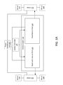
- FIG. 1 is a block diagram of a vehicle 100 , illustrating various aspects related to a battery system 102 , according to an example.
- the vehicle 100 is a primarily electric vehicle that is powered primarily or exclusively by electric power from the battery system 102 , as opposed to from chemical energy stored in a hydrocarbon fuel as in a more traditional vehicle.
- the battery system 102 is therefore configured with sufficient capacity and to provide sufficient power to move the vehicle 100 .
- the vehicle 100 includes the battery system 102 (which includes a battery controller 104 ), a battery recharge port 114 , a power distribution unit 105 , and one or more motors 106 coupled to a plurality of wheels 108 .
- the battery controller 104 can be any technically feasible control mechanism including a programmable processor that executes instructions stored in a memory, an application-specific integrated circuit, or any other technically feasible mechanism.
- the recharge port 114 includes a connector shaped and configured to connect to a recharger and to provide electrical energy from the recharger to the battery system 102 for recharging.
- the power distribution unit 105 includes circuitry configured to distribute power from the battery system 102 to the one or more motors 106 in any technically feasible manner.
- the battery system 102 includes a battery controller 104 , a fixed battery pack 110 , and a replaceable battery pack 112 .
- Each of the fixed battery pack 110 and the replaceable battery pack 112 includes a plurality of battery cells that are configured to store energy and to provide electrical energy from the stored energy on demand. The cells may be organized into battery modules and the battery modules may be further organized to form sub-packs.
- Each of the fixed battery pack 110 and the replaceable battery pack 112 includes one or more sub-packs.
- the fixed battery pack 110 is left in the vehicle 100 permanently or semi-permanently.
- the replaceable battery pack 112 is periodically removed from the vehicle 100 and replaced.
- the replaceable battery pack 112 thus has physical features such as proximity to an external surface of the vehicle 100 , easily accessible and switchable locks (electrically or mechanically controlled), or the like that allow for the replaceable battery pack 112 to be easily removed and for a replacement replaceable battery pack 112 to be installed.
- One purpose of removing the replaceable battery pack 112 is to allow for quick replenishment of battery-stored energy.
- Another purpose is to reduce the amount of time necessary to recharge battery energy for the vehicle 100 . For example, a driver could recharge a car by recharging only the fixed battery pack 110 while physically replacing a depleted replaceable battery pack 112 with a full replaceable battery pack 112 .
- the fixed battery pack 110 exists to provide the vehicle 100 with a relatively large amount of available battery power while limiting the physical size of the battery that is to be replaced. In other words, battery replacement is easier than if the entire battery system 102 were replaceable.
- the battery controller 104 controls various aspects of the battery system 102 .
- the battery controller 104 controls the manner in which the various components of the battery system 102 are charged and discharged.
- the battery controller 104 also controls the manner in which the battery system 102 provides electrical energy to the one or more motors 106 .
- the one or more motors 106 are powered by the battery system 102 and drive the wheels 108 to accelerate the vehicle 100 .
- one or more motors 106 powers front wheels 108 and one or more motors 106 powers rear wheels 108 .
- FIG. 1 illustrates two different motors 106 , each separately coupled to power different motors 106
- one or more motors 106 drives all wheels 108 or one or more motors 106 drive only one set of wheels (e.g., only front or only rear), with the other set of wheels being unpowered.
- the fixed battery pack 110 and replaceable battery pack 112 may cooperate to drive the one or more motors 106 or may drive the one or more motors 106 independently.
- FIGS. 2A, 2B, 3A, and 3B illustrate different ways in which the replaceable battery pack 112 and the fixed battery pack 110 provide power to drive the different motors 106 .
- the various ways in which the replaceable battery pack 112 and the fixed battery pack 110 provide power to the different motors 106 exist to accommodate the fact that the fixed battery pack 110 may have different age characteristics than the replaceable battery pack 112 . More specifically, because the fixed battery pack 110 is permanent or semi-permanent and the replaceable battery pack 112 is designed to be periodically swapped out for a different replaceable battery pack 112 , the age of the two battery packs will generally not be the same. As is known, an aged battery pack has higher internal resistance than a newer battery pack.
- an aged battery pack would have a different voltage across its terminals under the same current draw conditions as compared with a newer battery pack. For this reason, if two battery packs of different age are used to power the same motor 106 (e.g., by connecting the two battery packs in parallel), then the battery packs would be limited by the more aged battery pack, leading to inefficiencies. For this reason, the replaceable battery pack 112 and the fixed battery pack 110 are not used to power the same motors 106 .
- FIG. 2A is a block diagram of the battery system 102 of FIG. 1 in a configuration in which the fixed battery pack 110 provides power to drive both motors 106 , according to an example. More specifically, the battery controller 104 controls the fixed battery pack 110 to provide energy to drive both motors 106 to control both sets of wheels 108 . Thus, power from the fixed battery pack 110 can be used to power the motors 106 while the replaceable battery pack 112 is not used to power the motors 106 .
- FIG. 2B is a block diagram of the battery system 102 of FIG. 1 in a configuration in which the replaceable battery pack 112 provides power to drive both motors 106 , according to an example. More specifically, the battery controller 104 controls the replaceable battery pack 112 to provide energy to drive both motors 106 to control both sets of wheels 108 . Thus, power from the replaceable battery pack 112 can be used to power the motors 106 while the fixed battery pack 110 is not used to power the motors 106 .
- FIGS. 3A and 3B illustrate configurations in which the replaceable battery pack 112 and the fixed battery pack 110 provide power to different motors 106 .
- the battery controller 104 is capable of switching between any of the configurations illustrated in FIGS. 2A, 2B, 3A, and 3B based on a variety of factors. Some examples are now provided.
- the battery controller 104 monitors the output (e.g., voltage) of fixed battery pack 110 and the replaceable battery pack 112 and controls which battery pack provides power to the motors 106 based on the results of the monitoring. In some embodiments, the battery controller 104 causes the replaceable battery pack 112 to power one or both motors 106 before causing the fixed battery pack 110 to begin discharging to power one or more motors 106 . The battery controller 104 may cause the replaceable battery pack 112 to be discharged (e.g., to power the motors 106 ) to a minimum charge threshold before the battery controller 104 causes the fixed battery pack 110 to discharge (to power the motors 106 ).
- the replaceable battery pack 112 may be discharged (e.g., to power the motors 106 ) to a minimum charge threshold before the battery controller 104 causes the fixed battery pack 110 to discharge (to power the motors 106 ).
- the battery controller 104 may also cause the fixed battery pack 110 and the replaceable battery pack 112 to provide power to both motors 106 separately (i.e., as shown in FIGS. 2A and 2B ) when both battery packs are not yet discharged.
- the battery controller 104 may cause the battery pack with the greater charge to power the motor 106 that requires more power, while causing the battery pack with the lower charge to power the motor 106 that requires less power.
- the battery controller 104 may cause the battery pack with the greater charge to power the motor 106 or motors while letting the battery pack with the lower charge to remain unused.
- the battery controller 104 may discharge the replaceable battery pack 112 before discharging the fixed battery pack 110 .
- the purpose of controlling the fixed battery pack 110 and replaceable battery pack 112 as described above is to prevent the inefficiencies associated with connecting two differently aged batteries in parallel. More specifically, when connected in parallel, because the internal resistance of one of the batteries is higher than the internal resistance of the other battery, the voltage driven by the connected batteries is limited to the lower voltage of the more aged battery. This result in inefficiencies in that the younger battery operates at a lower voltage than it is able. Disconnecting the batteries thus prevents these inefficiencies from occurring.
- the battery controller 104 In addition to controlling the manner in which the battery packs discharge to power the one or more motors 106 , the battery controller 104 also controls the manner in which the battery packs are charged via the recharge port 114 . In one example, the battery controller 104 charges the fixed battery pack 110 before charging the replaceable battery pack 112 . In other words, if both the fixed battery pack 110 and the replaceable battery pack 112 are substantially discharged, then the battery controller 104 controls the fixed battery pack 110 to be charged (via the recharge port 114 ) before controlling the replaceable battery pack 112 to be recharged.
- FIG. 4 is a block diagram of a battery pack 402 that can be one of a fixed battery pack 110 or a replaceable battery pack 112 , according to an example.
- the battery pack 402 includes a battery control unit 410 that controls operation of sub-packs 403 of the battery pack 402 .
- the sub-packs 403 each include one or more modules 404 , which each include a module control unit 408 and one or more cells 406 .
- the cells 406 store energy in chemical form and convert the energy to electrical energy on demand.
- the cells 406 are connected in series and/or in parallel to produce electricity in a desired characteristic.
- the module control units 408 detect cell status with voltage and temperature sensors and transmits such data to the battery control unit 410 .
- One or more modules 404 are provided in each sub-pack 403 and are connected in parallel and/or in series in order to provide electrical energy having desired characteristics.
- a battery control unit 410 receives, calculates, and makes judgment about the data from the module control units 408 to decide how to connect the modules 404 together.
- the battery pack 402 may include one battery control unit 410 that controls all of the sub-packs 403 or may include one battery control unit 410 for each of the sub-packs 403 .
- the battery pack 402 illustrates an example configuration for the replaceable battery pack 112 or the fixed battery pack 110 .
- the number of components such as sub-packs 403 , battery control units 410 , modules 404 , module control units 408 , and cells 406 , may be different in the fixed battery pack 110 as compared with the replaceable battery pack 112 .
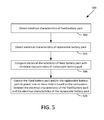
- FIG. 5 is a flow diagram of a method 500 for controlling battery discharge, according to an example. Although described with respect to the system shown and described with respect to FIGS. 1-3 , it should be understood that any system configured to perform the method, in any technically feasible order, falls within the scope of the present disclosure.
- the method 500 begins at step 502 , where the battery controller 104 detects electrical characteristics of the fixed battery pack 110 .
- the battery controller 104 detects the voltage across the terminals of the fixed battery pack 110 when under load conditions associated with powering the motor.
- the battery controller 104 detects electrical characteristics of the replaceable battery pack 112 in a similar manner as with the electrical characteristics of the fixed battery pack 110 .
- the battery controller 104 compares the electrical characteristics of the fixed battery pack 110 with the electrical characteristics of the replaceable battery pack 112 . In one example, the battery controller 104 determines whether the replaceable battery pack 112 has been completely discharged, which is determined based on whether an output voltage of the replaceable battery pack 112 has dropped below a minimum threshold (a “charging threshold”) that indicates that the replaceable battery pack 112 has been discharged. Additionally or alternatively, the battery controller 104 may determine that an amount of power is required for vehicle use in addition to the amount of power that can be provided by either the replaceable battery pack 112 or fixed battery pack 110 alone.
- a minimum threshold a “charging threshold”
- the battery controller 104 controls the fixed battery pack 110 and/or the replaceable battery pack 112 to power one or more of the motors 106 based on the comparison between the electrical characteristics of the fixed battery pack 110 and the electrical characteristics of the replaceable battery pack 112 .
- the battery controller 104 switches from causing the replaceable battery pack 112 to charge to motors 106 to causing the fixed battery pack 110 to charge the motors 106 .
- the battery controller 104 may determine that an amount of power is required for vehicle use in addition to the amount of power that can be provided by either the replaceable battery pack 112 or fixed battery pack 110 alone. In response, the battery controller 104 causes the fixed battery pack 110 to power one set of wheels 108 and causes the replaceable battery pack 112 to power a different set of wheels 108 at the same time. The battery controller 104 may cause the fixed battery pack 110 and replaceable battery pack 112 to power different sets of wheels 108 for reasons other than simply a power requirement.
Landscapes
- Engineering & Computer Science (AREA)
- Chemical & Material Sciences (AREA)
- Power Engineering (AREA)
- Electrochemistry (AREA)
- General Chemical & Material Sciences (AREA)
- Chemical Kinetics & Catalysis (AREA)
- Transportation (AREA)
- Mechanical Engineering (AREA)
- Manufacturing & Machinery (AREA)
- Life Sciences & Earth Sciences (AREA)
- Sustainable Development (AREA)
- Sustainable Energy (AREA)
- Microelectronics & Electronic Packaging (AREA)
- Combustion & Propulsion (AREA)
- Aviation & Aerospace Engineering (AREA)
- Electric Propulsion And Braking For Vehicles (AREA)
Abstract
Description
Claims (20)
Priority Applications (1)
| Application Number | Priority Date | Filing Date | Title |
|---|---|---|---|
| US15/283,953 US10076971B2 (en) | 2016-07-05 | 2016-10-03 | Split electric vehicle (EV) battery including both a replaceable and fixed portion |
Applications Claiming Priority (2)
| Application Number | Priority Date | Filing Date | Title |
|---|---|---|---|
| US201662358329P | 2016-07-05 | 2016-07-05 | |
| US15/283,953 US10076971B2 (en) | 2016-07-05 | 2016-10-03 | Split electric vehicle (EV) battery including both a replaceable and fixed portion |
Publications (2)
| Publication Number | Publication Date |
|---|---|
| US20180009331A1 US20180009331A1 (en) | 2018-01-11 |
| US10076971B2 true US10076971B2 (en) | 2018-09-18 |
Family
ID=60892526
Family Applications (1)
| Application Number | Title | Priority Date | Filing Date |
|---|---|---|---|
| US15/283,953 Active US10076971B2 (en) | 2016-07-05 | 2016-10-03 | Split electric vehicle (EV) battery including both a replaceable and fixed portion |
Country Status (1)
| Country | Link |
|---|---|
| US (1) | US10076971B2 (en) |
Cited By (6)
| Publication number | Priority date | Publication date | Assignee | Title |
|---|---|---|---|---|
| US10550818B2 (en) * | 2017-04-12 | 2020-02-04 | Hyundai Motor Company | Apparatus and method for controlling start sequence of engine for vehicle |
| US10727680B2 (en) | 2017-09-22 | 2020-07-28 | Nio Usa, Inc. | Power systems and methods for electric vehicles |
| US20220363160A1 (en) * | 2021-05-17 | 2022-11-17 | Kubota Corporation | Working vehicle |
| US20220371452A1 (en) * | 2019-10-08 | 2022-11-24 | Sten Corfitsen | Electric vehicle with modular battery system |
| US20230278457A1 (en) * | 2020-12-15 | 2023-09-07 | Zhejiang Geely Holding Group Co., Ltd. | Battery replacement vehicle without intermediate transmission shaft |
| EP4371809A1 (en) * | 2022-11-16 | 2024-05-22 | Volvo Construction Equipment AB | A battery arrangement |
Families Citing this family (8)
| Publication number | Priority date | Publication date | Assignee | Title |
|---|---|---|---|---|
| JP7401444B2 (en) * | 2018-02-10 | 2023-12-19 | ヨウオン テクノロジー カンパニー、リミテッド | Electrically assisted bicycle, its power management system and management method |
| US12485796B2 (en) * | 2019-02-11 | 2025-12-02 | Transportation Ip Holdings, Llc | Vehicle electric supply system |
| WO2021080536A1 (en) * | 2019-10-21 | 2021-04-29 | Turkiye'nin Otomobili Girisim Grubu Sanayi Ve Ticaret A.S. | Electric vehicle with semi-replaceable battery and replaceable battery system and mechanical connection structure |
| LU102631B1 (en) * | 2021-03-09 | 2022-09-09 | Jean Claude Galland | METHODS AND DEVICES FOR POWERING AN ELECTRIC VEHICLE BY BATTERY OF TWO-PART ACCUMULATORS |
| JP2022184602A (en) * | 2021-06-01 | 2022-12-13 | 本田技研工業株式会社 | Electric vehicle and sharing system |
| EP4134269A1 (en) * | 2021-08-12 | 2023-02-15 | Lilium eAircraft GmbH | Power distribution system for an electric air vehicle |
| CN117559054A (en) * | 2022-08-04 | 2024-02-13 | 本田技研工业(中国)投资有限公司 | Battery packs and vehicles |
| CN118372716B (en) * | 2024-06-21 | 2024-08-16 | 湖南振翔电气科技有限公司 | Design method of electric drive electric system with power exchanging and power standby functions |
Citations (22)
| Publication number | Priority date | Publication date | Assignee | Title |
|---|---|---|---|---|
| US6044922A (en) * | 1992-05-08 | 2000-04-04 | Field; Bruce F. | Electric hybrid vehicle |
| US6075346A (en) * | 1997-10-13 | 2000-06-13 | Toyota Jidosha Kabushiki Kaisha | Secondary battery charge and discharge control device |
| US6781343B1 (en) * | 2000-09-20 | 2004-08-24 | Honda Giken Kogyo Kabushiki Kaisha | Hybrid power supply device |
| US20080111508A1 (en) * | 2001-04-05 | 2008-05-15 | Electrovaya Inc. | Energy storage device for loads having variabl power rates |
| US20080218104A1 (en) * | 2007-03-09 | 2008-09-11 | Srdjan Lukic | Power management for multi-module energy storage systems in electric, hybrid electric, and fuel cell vehicles |
| US20090033253A1 (en) * | 2007-07-30 | 2009-02-05 | Gm Global Technology Operations, Inc. | Electric traction system for a vehicle having a dual winding ac traction motor |
| US20090033258A1 (en) * | 2007-08-03 | 2009-02-05 | Honda Motor Co., Ltd. | Motor controller |
| US20090033252A1 (en) * | 2007-07-30 | 2009-02-05 | Gm Global Technology Operations, Inc. | Double ended inverter system for a vehicle having two energy sources that exhibit different operating characteristics |
| US20090034308A1 (en) * | 2007-07-30 | 2009-02-05 | Gm Global Technology Operations, Inc. | Double ended inverter system with an impedance source inverter subsystem |
| US20090173554A1 (en) * | 2006-06-01 | 2009-07-09 | Takeuchi Mfg. Co., Ltd. | Working vehicle |
| US20100019729A1 (en) * | 2008-07-25 | 2010-01-28 | Toyota Jidosha Kabushiki Kaisha | Power supply system and vehicle with the system |
| US20100019723A1 (en) * | 2007-02-20 | 2010-01-28 | Toyota Jidosha Kabushiki Kaisha | Electric powered vehicle, vehicle charge device and vehicle charge system |
| US20100065351A1 (en) * | 2007-02-13 | 2010-03-18 | Toyota Jidosha Kabushiki Kaisha | Driving force generation system, vehicle using the system, and method for controlling the system |
| US20100138087A1 (en) * | 2007-05-23 | 2010-06-03 | Tooyota Jidosha Kabushiki Kaisha | On-vehicle equipment control system and vehicle |
| US20100136390A1 (en) * | 2008-11-28 | 2010-06-03 | Hitachi, Ltd. | Battery Storage System |
| US20110313613A1 (en) * | 2009-03-27 | 2011-12-22 | Hitachi Vechicle Energy, Ltd. | Electric Storage Device |
| US20130038271A1 (en) * | 2011-08-09 | 2013-02-14 | Hyundai Motor Company | Control method of hybrid vehicle |
| US20140350761A1 (en) * | 2011-12-15 | 2014-11-27 | Toyota Jidosha Kabushiki Kaisha | Hybrid vehicle |
| US20140358347A1 (en) * | 2011-12-15 | 2014-12-04 | Toyota Jidosha Kabushiki Kaisha | Hybrid vehicle |
| US20150217660A1 (en) * | 2012-07-20 | 2015-08-06 | Toyota Jidosha Kabushiki Kaisha | Fuel cell system |
| US20150298571A1 (en) * | 2014-04-21 | 2015-10-22 | Samsung Electro-Mechanics Co., Ltd. | Driving circuit for hybrid electric vehicle and controlling method thereof |
| US20160052396A1 (en) * | 2014-08-25 | 2016-02-25 | Toyota Jidosha Kabushiki Kaisha | Electric vehicle |
-
2016
- 2016-10-03 US US15/283,953 patent/US10076971B2/en active Active
Patent Citations (33)
| Publication number | Priority date | Publication date | Assignee | Title |
|---|---|---|---|---|
| US6481516B1 (en) * | 1992-05-08 | 2002-11-19 | Field Hybrids, Llc | Electric hybrid vehicle |
| US6044922A (en) * | 1992-05-08 | 2000-04-04 | Field; Bruce F. | Electric hybrid vehicle |
| US6075346A (en) * | 1997-10-13 | 2000-06-13 | Toyota Jidosha Kabushiki Kaisha | Secondary battery charge and discharge control device |
| US6781343B1 (en) * | 2000-09-20 | 2004-08-24 | Honda Giken Kogyo Kabushiki Kaisha | Hybrid power supply device |
| US7570012B2 (en) * | 2001-04-05 | 2009-08-04 | Electrovaya Inc. | Energy storage device for loads having variable power rates |
| US20080111508A1 (en) * | 2001-04-05 | 2008-05-15 | Electrovaya Inc. | Energy storage device for loads having variabl power rates |
| US8030860B2 (en) * | 2006-06-01 | 2011-10-04 | Takeuchi Mfg Co., Ltd. | Working vehicle |
| US20090173554A1 (en) * | 2006-06-01 | 2009-07-09 | Takeuchi Mfg. Co., Ltd. | Working vehicle |
| US8053921B2 (en) * | 2007-02-13 | 2011-11-08 | Toyota Jidosha Kabushiki Kaisha | Driving force generation system, vehicle using the system, and method for controlling the system |
| US20100065351A1 (en) * | 2007-02-13 | 2010-03-18 | Toyota Jidosha Kabushiki Kaisha | Driving force generation system, vehicle using the system, and method for controlling the system |
| US8618771B2 (en) * | 2007-02-20 | 2013-12-31 | Toyota Jidosha Kabushiki Kaisha | Electric powered vehicle, vehicle charge device and vehicle charge system |
| US20100019723A1 (en) * | 2007-02-20 | 2010-01-28 | Toyota Jidosha Kabushiki Kaisha | Electric powered vehicle, vehicle charge device and vehicle charge system |
| US20080218104A1 (en) * | 2007-03-09 | 2008-09-11 | Srdjan Lukic | Power management for multi-module energy storage systems in electric, hybrid electric, and fuel cell vehicles |
| US20130300191A1 (en) * | 2007-05-23 | 2013-11-14 | Toyota Jidosha Kabushiki Kaisha | On-vehicle equipment control system and vehicle |
| US8515605B2 (en) * | 2007-05-23 | 2013-08-20 | Toyota Jidosha Kabushiki Kaisha | On-vehicle equipment control system and vehicle |
| US20100138087A1 (en) * | 2007-05-23 | 2010-06-03 | Tooyota Jidosha Kabushiki Kaisha | On-vehicle equipment control system and vehicle |
| US20090033253A1 (en) * | 2007-07-30 | 2009-02-05 | Gm Global Technology Operations, Inc. | Electric traction system for a vehicle having a dual winding ac traction motor |
| US7956569B2 (en) * | 2007-07-30 | 2011-06-07 | GM Global Technology Operations LLC | Double ended inverter system with an impedance source inverter subsystem |
| US20090034308A1 (en) * | 2007-07-30 | 2009-02-05 | Gm Global Technology Operations, Inc. | Double ended inverter system with an impedance source inverter subsystem |
| US20090033252A1 (en) * | 2007-07-30 | 2009-02-05 | Gm Global Technology Operations, Inc. | Double ended inverter system for a vehicle having two energy sources that exhibit different operating characteristics |
| US8102142B2 (en) * | 2007-07-30 | 2012-01-24 | GM Global Technology Operations LLC | Double ended inverter system for a vehicle having two energy sources that exhibit different operating characteristics |
| US20090033258A1 (en) * | 2007-08-03 | 2009-02-05 | Honda Motor Co., Ltd. | Motor controller |
| US20100019729A1 (en) * | 2008-07-25 | 2010-01-28 | Toyota Jidosha Kabushiki Kaisha | Power supply system and vehicle with the system |
| US8395355B2 (en) * | 2008-07-25 | 2013-03-12 | Toyota Jidosha Kabushiki Kaisha | Power supply system and vehicle with the system |
| US20100136390A1 (en) * | 2008-11-28 | 2010-06-03 | Hitachi, Ltd. | Battery Storage System |
| US8486548B2 (en) * | 2008-11-28 | 2013-07-16 | Hitachi, Ltd. | Battery storage system |
| US20110313613A1 (en) * | 2009-03-27 | 2011-12-22 | Hitachi Vechicle Energy, Ltd. | Electric Storage Device |
| US20130038271A1 (en) * | 2011-08-09 | 2013-02-14 | Hyundai Motor Company | Control method of hybrid vehicle |
| US20140350761A1 (en) * | 2011-12-15 | 2014-11-27 | Toyota Jidosha Kabushiki Kaisha | Hybrid vehicle |
| US20140358347A1 (en) * | 2011-12-15 | 2014-12-04 | Toyota Jidosha Kabushiki Kaisha | Hybrid vehicle |
| US20150217660A1 (en) * | 2012-07-20 | 2015-08-06 | Toyota Jidosha Kabushiki Kaisha | Fuel cell system |
| US20150298571A1 (en) * | 2014-04-21 | 2015-10-22 | Samsung Electro-Mechanics Co., Ltd. | Driving circuit for hybrid electric vehicle and controlling method thereof |
| US20160052396A1 (en) * | 2014-08-25 | 2016-02-25 | Toyota Jidosha Kabushiki Kaisha | Electric vehicle |
Cited By (8)
| Publication number | Priority date | Publication date | Assignee | Title |
|---|---|---|---|---|
| US10550818B2 (en) * | 2017-04-12 | 2020-02-04 | Hyundai Motor Company | Apparatus and method for controlling start sequence of engine for vehicle |
| US10727680B2 (en) | 2017-09-22 | 2020-07-28 | Nio Usa, Inc. | Power systems and methods for electric vehicles |
| US20220371452A1 (en) * | 2019-10-08 | 2022-11-24 | Sten Corfitsen | Electric vehicle with modular battery system |
| US20230278457A1 (en) * | 2020-12-15 | 2023-09-07 | Zhejiang Geely Holding Group Co., Ltd. | Battery replacement vehicle without intermediate transmission shaft |
| US12491790B2 (en) * | 2020-12-15 | 2025-12-09 | Zhejiang Geely Holding Group Co., Ltd. | Battery replacement vehicle without intermediate transmission shaft |
| US20220363160A1 (en) * | 2021-05-17 | 2022-11-17 | Kubota Corporation | Working vehicle |
| US12151584B2 (en) * | 2021-05-17 | 2024-11-26 | Kubota Corporation | Working vehicle |
| EP4371809A1 (en) * | 2022-11-16 | 2024-05-22 | Volvo Construction Equipment AB | A battery arrangement |
Also Published As
| Publication number | Publication date |
|---|---|
| US20180009331A1 (en) | 2018-01-11 |
Similar Documents
| Publication | Publication Date | Title |
|---|---|---|
| US10076971B2 (en) | Split electric vehicle (EV) battery including both a replaceable and fixed portion | |
| KR101680526B1 (en) | Battery management apparatus and method | |
| CN103085665B (en) | Car power source apparatus and vehicle equipped with the power source apparatus | |
| US10195929B2 (en) | Electrically-driven vehicle | |
| CN105703447B (en) | Direct Balance Charging Method for Rechargeable Batteries | |
| KR102016752B1 (en) | Battery pack and method for controlling the same | |
| US20210257843A1 (en) | Battery system and a method for use in the battery system | |
| US9707854B2 (en) | Series booster pack for battery system capacity recovery | |
| EP2741395B1 (en) | Apparatus and method for charging a battery | |
| US20130057219A1 (en) | Power supply apparatus for vehicle and vehicle provided with same | |
| US10461546B2 (en) | System and method of managing battery by using balancing battery | |
| US20120037438A1 (en) | Hybrid Electric Vehicle Battery Protection System Through Capacitor Bank Energy Buffer | |
| US10333179B2 (en) | Method for operating a battery system, battery system and motor vehicle | |
| US10608291B2 (en) | Battery pack having a supplemental power supply | |
| WO2017207997A1 (en) | Electric vehicle battery management apparatus and method | |
| US20140327298A1 (en) | Energy storage arrangement | |
| CN104827990B (en) | Vehicle battery system | |
| WO2013186209A2 (en) | A rechargeable electric battery pack for a vehicle | |
| CN105150874B (en) | Power battery management system and power supply control method thereof | |
| CN106956602B (en) | Battery pack and electric vehicle including the same | |
| CN116061670A (en) | Battery system and method for controlling battery system | |
| CN110816311B (en) | Method for operating a battery system and electric vehicle | |
| CN110435481A (en) | Battery system and can electrically driven motor vehicle | |
| US20190225108A1 (en) | Method and system of smart management of electrochemical batteries for an electric vehicle | |
| US11951871B2 (en) | Multi-voltage storage system for an at least partly electrically driven vehicle |
Legal Events
| Date | Code | Title | Description |
|---|---|---|---|
| AS | Assignment |
Owner name: NIO NEXTEV LIMITED, HONG KONG Free format text: ASSIGNMENT OF ASSIGNORS INTEREST;ASSIGNORS:HUANG, CHENDONG;FANG, JIE;ZHAO, WENPENG;AND OTHERS;REEL/FRAME:045901/0509 Effective date: 20180410 |
|
| STCF | Information on status: patent grant |
Free format text: PATENTED CASE |
|
| CC | Certificate of correction | ||
| AS | Assignment |
Owner name: NIO (ANHUI) HOLDING CO., LTD., CHINA Free format text: ASSIGNMENT OF ASSIGNORS INTEREST;ASSIGNOR:NIO NEXTEV LIMITED;REEL/FRAME:054280/0562 Effective date: 20200930 |
|
| MAFP | Maintenance fee payment |
Free format text: PAYMENT OF MAINTENANCE FEE, 4TH YEAR, LARGE ENTITY (ORIGINAL EVENT CODE: M1551); ENTITY STATUS OF PATENT OWNER: LARGE ENTITY Year of fee payment: 4 |
|
| MAFP | Maintenance fee payment |
Free format text: PAYMENT OF MAINTENANCE FEE, 8TH YEAR, LARGE ENTITY (ORIGINAL EVENT CODE: M1552); ENTITY STATUS OF PATENT OWNER: LARGE ENTITY Year of fee payment: 8 |