US1007643A - Radiator. - Google Patents
Radiator. Download PDFInfo
- Publication number
- US1007643A US1007643A US58201310A US1910582013A US1007643A US 1007643 A US1007643 A US 1007643A US 58201310 A US58201310 A US 58201310A US 1910582013 A US1910582013 A US 1910582013A US 1007643 A US1007643 A US 1007643A
- Authority
- US
- United States
- Prior art keywords
- radiator
- corrugations
- members
- walls
- reinforcing
- Prior art date
- Legal status (The legal status is an assumption and is not a legal conclusion. Google has not performed a legal analysis and makes no representation as to the accuracy of the status listed.)
- Expired - Lifetime
Links
- 230000003014 reinforcing effect Effects 0.000 description 20
- 239000000463 material Substances 0.000 description 6
- 238000010276 construction Methods 0.000 description 5
- 230000005855 radiation Effects 0.000 description 5
- 239000002184 metal Substances 0.000 description 3
- 229910052751 metal Inorganic materials 0.000 description 3
- 230000015572 biosynthetic process Effects 0.000 description 2
- 229910001018 Cast iron Inorganic materials 0.000 description 1
- CWYNVVGOOAEACU-UHFFFAOYSA-N Fe2+ Chemical compound [Fe+2] CWYNVVGOOAEACU-UHFFFAOYSA-N 0.000 description 1
- 229910000754 Wrought iron Inorganic materials 0.000 description 1
- 239000012530 fluid Substances 0.000 description 1
- 238000010438 heat treatment Methods 0.000 description 1
Images
Classifications
-
- F—MECHANICAL ENGINEERING; LIGHTING; HEATING; WEAPONS; BLASTING
- F28—HEAT EXCHANGE IN GENERAL
- F28D—HEAT-EXCHANGE APPARATUS, NOT PROVIDED FOR IN ANOTHER SUBCLASS, IN WHICH THE HEAT-EXCHANGE MEDIA DO NOT COME INTO DIRECT CONTACT
- F28D1/00—Heat-exchange apparatus having stationary conduit assemblies for one heat-exchange medium only, the media being in contact with different sides of the conduit wall, in which the other heat-exchange medium is a large body of fluid, e.g. domestic or motor car radiators
- F28D1/02—Heat-exchange apparatus having stationary conduit assemblies for one heat-exchange medium only, the media being in contact with different sides of the conduit wall, in which the other heat-exchange medium is a large body of fluid, e.g. domestic or motor car radiators with heat-exchange conduits immersed in the body of fluid
- F28D1/04—Heat-exchange apparatus having stationary conduit assemblies for one heat-exchange medium only, the media being in contact with different sides of the conduit wall, in which the other heat-exchange medium is a large body of fluid, e.g. domestic or motor car radiators with heat-exchange conduits immersed in the body of fluid with tubular conduits
- F28D1/053—Heat-exchange apparatus having stationary conduit assemblies for one heat-exchange medium only, the media being in contact with different sides of the conduit wall, in which the other heat-exchange medium is a large body of fluid, e.g. domestic or motor car radiators with heat-exchange conduits immersed in the body of fluid with tubular conduits the conduits being straight
-
- F—MECHANICAL ENGINEERING; LIGHTING; HEATING; WEAPONS; BLASTING
- F28—HEAT EXCHANGE IN GENERAL
- F28D—HEAT-EXCHANGE APPARATUS, NOT PROVIDED FOR IN ANOTHER SUBCLASS, IN WHICH THE HEAT-EXCHANGE MEDIA DO NOT COME INTO DIRECT CONTACT
- F28D21/00—Heat-exchange apparatus not covered by any of the groups F28D1/00 - F28D20/00
- F28D2021/0019—Other heat exchangers for particular applications; Heat exchange systems not otherwise provided for
- F28D2021/0035—Other heat exchangers for particular applications; Heat exchange systems not otherwise provided for for domestic or space heating, e.g. heating radiators
Definitions
- This invention relates to radiators, more particularly to steam radiators, although the invention may be used in any connection in which it is found to be applicable.
- the invention is particularly applicable to radiators having grooved or corrugated side members forming radiation chambers, and in accordance with this invention I provide reinforcing members between certain of the opposing walls of the grooves or corrugations, either inside or outside of the radiator, or both, and at any desired vertical position with respect to the radiator.
- the reinforcing members may be of any suitable or desired form and construction and serve to prevent deformation of the walls of the radiation chambers.
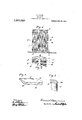
- FIG. 1 is a side elevation of a radiator embodying the improvements
- Fig. 2 is a horizontal sectional view of a radiator partly broken away
- Fig. 3 is a perspective view of one of the braces
- Fig. 4 is an enlarged detail sectional view on the line 2-2 of Fig. 2.
- the radiator illustrating the preferred embodiment of the invention comprises a body portion preferably of relatively thin sheet metal.
- the side walls 0 and D of the body portion are provided with corrugations of suflicient depth to form radiation chambers having efficient radiating surfaces.
- a and B represent the top and bottom members of the radiator which may be conveniently formed of cast metal.
- the body portion is fitted to the top and bottom members A and B, pref erably by means of the rabbets 10 shown in Fig. 1.
- the corrugations extend inwardly leaving a central space 11 extending from top to bottom of the radiator, throughwhich the steam or other heating fluid may circulate.
- radiator may be formed with grooves which are the equivalent of the spaces between the corrugations shown in the drawings, so that any form of side member may be used having corrugations therein.
- braces adapted to be placed between the opposing walls of the corrugations and either inside or outside of the body portion of the radiator, or both inside and outside, as desired.
- the braces E as shown in this instance may be formed of suitable material as cast or wrought iron and may be in the form of U-shaped members, the sides 12 of which are preferably connected by the transverse struts 13 and 11 of which there may be any desired number. If the bracing member E is formed of cast metal, the struts 13 and 14 are preferably cast integral therewith.
- the back 15 of the member E is preferably curved to conform to the inner curved portions of the corrugations.
- bracing member E I have shown by way of illustration is placed at any desired height either inside or outside of the radiator and between the opposing surfaces of a corrugation or groove.
- Fig. 1 the bracing members are shown at different heights on the outside of the radiator and in Fig. 2 the bracing members are shown both inside and outside of Patented Oct. 31, 1911.
- the bracing members are located at such distances apart as are deemed necessary to effectually reinforce the entire structure.
- the reinforcing members are preferably adapted to conform to the surfaces of the corrugations or grooves and may be placed in certain of the grooves or in at least some of the grooves, as desired.
- the present invention provides means whereby the radiator may be manufactured of extremely thin material and the strain on the walls of the chambers is resisted by the reinforcing members.
- the pressure from the inside is resisted by the reinforcing members placed outside of the radiator.
- the walls of the chambers are prevented from buckling due to the formation of partial vacuum, by placing reinforc-- ing members inside of the radiator.
- a radiator having side walls of relatively thin material formed with corrugations of sufficient depth to form radiation chambers, and exterior reinforcing members arranged between the outer surfaces of the opposing walls of at least some of the chambers, said reinforcing members conforming substantially to the shape of said chambers.
- a radiator having side walls of relatively thin material formed with chambers, and reinforcing means arranged between the opposing walls of certain of said chambers, said reinforcing means comprising members having fiat sides connected by struts.
- a radiator in a radiator the combination of a side wall having corrugations, of a plurality of exterior and interior reinforcing members located in the corrugations and formed with portions fitting closely to the surfaces of the corrugations and conforming thereto.
Landscapes
- Engineering & Computer Science (AREA)
- Physics & Mathematics (AREA)
- Thermal Sciences (AREA)
- Mechanical Engineering (AREA)
- General Engineering & Computer Science (AREA)
- Physical Or Chemical Processes And Apparatus (AREA)
Description
F. CLARE.
RADIATOR.
APPLICATION FILED $2217.14, 1910.
1,007,643. Patented 00c. 31, 1911.
wi/ta Le-ioea I w 5] woe Moe $1,1MEuW/M W FREDERICK CLARE, 0F PRESTON, ONTARIO, CANADA.
RADIATOR.
Specification of Letters Patent.
Application filed September 14, 1910. Serial No. 582,013.
To all whom it may concern Be it known that I, FREDERICK CLARE, a subject of the Dominion of Canada, and a resident of Preston, Province of Ontario, Dominion of Canada, have invented certain new and useful Improvements in Radiators, of which the following is a specification, accompanied by drawings.
This invention relates to radiators, more particularly to steam radiators, although the invention may be used in any connection in which it is found to be applicable.
Difliculty has been experienced with radiators constructed of relatively thin material, owing to the fact that the walls are apt to buckle due to'the pressure from the inside or from the formation of a partial vacuum, and the objects of this invention are to improve upon the construction of such radiators and enable the walls to be constructed of relatively thin material without the attendant disadvantages due to buckling and deformation, which tend to lessen the efficiency of the radiator.
The invention is particularly applicable to radiators having grooved or corrugated side members forming radiation chambers, and in accordance with this invention I provide reinforcing members between certain of the opposing walls of the grooves or corrugations, either inside or outside of the radiator, or both, and at any desired vertical position with respect to the radiator. The reinforcing members may be of any suitable or desired form and construction and serve to prevent deformation of the walls of the radiation chambers.
Further objects of the invention will hereinafter appear and to all of these ends the invention consists of a radiator construction embodying the combinations of elements and arrangement of parts substantially as hereinafter fully described and claimed in this specification and shown in one of its preferred embodiments in the accompanying drawings, in which Figure 1 is a side elevation of a radiator embodying the improvements; Fig. 2 is a horizontal sectional view of a radiator partly broken away; Fig. 3 is a perspective view of one of the braces; and Fig. 4 is an enlarged detail sectional view on the line 2-2 of Fig. 2.
Referring to the drawings, the radiator illustrating the preferred embodiment of the invention comprises a body portion preferably of relatively thin sheet metal. The side walls 0 and D of the body portion are provided with corrugations of suflicient depth to form radiation chambers having efficient radiating surfaces. A and B represent the top and bottom members of the radiator which may be conveniently formed of cast metal. The body portion is fitted to the top and bottom members A and B, pref erably by means of the rabbets 10 shown in Fig. 1. In the corrugated form of radiator shown, the corrugations extend inwardly leaving a central space 11 extending from top to bottom of the radiator, throughwhich the steam or other heating fluid may circulate.
I am not to be understood as limiting the invention to corrugated form of radiator construction, for the radiator may be formed with grooves which are the equivalent of the spaces between the corrugations shown in the drawings, so that any form of side member may be used having corrugations therein.
In order to reinforce the substantially thin walls of the radiation chambers formed by the corrugations or grooves, I provide reinforcing means in the form of braces adapted to be placed between the opposing walls of the corrugations and either inside or outside of the body portion of the radiator, or both inside and outside, as desired. I have illustrated a suitable form of bracing member at E, although I am not to be understood as limiting myself to this particular form of reinforcing means. The braces E as shown in this instance may be formed of suitable material as cast or wrought iron and may be in the form of U-shaped members, the sides 12 of which are preferably connected by the transverse struts 13 and 11 of which there may be any desired number. If the bracing member E is formed of cast metal, the struts 13 and 14 are preferably cast integral therewith. The back 15 of the member E is preferably curved to conform to the inner curved portions of the corrugations.
The particular form of a bracing member E, I have shown by way of illustration is placed at any desired height either inside or outside of the radiator and between the opposing surfaces of a corrugation or groove. In Fig. 1 the bracing members are shown at different heights on the outside of the radiator and in Fig. 2 the bracing members are shown both inside and outside of Patented Oct. 31, 1911.
the radiator. The bracing members are located at such distances apart as are deemed necessary to effectually reinforce the entire structure. The reinforcing members are preferably adapted to conform to the surfaces of the corrugations or grooves and may be placed in certain of the grooves or in at least some of the grooves, as desired.
It will be seen that the present invention provides means whereby the radiator may be manufactured of extremely thin material and the strain on the walls of the chambers is resisted by the reinforcing members. The pressure from the inside is resisted by the reinforcing members placed outside of the radiator. The walls of the chambers are prevented from buckling due to the formation of partial vacuum, by placing reinforc-- ing members inside of the radiator.
As many changes could be madein the construction disclosed and many apparently widely different embodiments of the invention within the scope of the claims could be made withoutdeparting from the spirit or scope thereof, it is understood and intended that all matter contained in the accompanying specification and drawings shall be interpreted as illustrative and not in a limiting sense.
I claim and desire to obtain by Letters Patent the following:
1. In a radiator, the combination with a side wall Having vertical corrugations, of a plurality of independent reinforcing members located in the corrugations and formed with portions fitting closely to the surfaces of the corrugations and conforming substantially to the shape of said corrugations.
2. In a radiator the combination with a relatively thin grooved side wall, of a reinforcing member in the groove on the exterior adapted to conform to the surface of the groove, said reinforcing member being formed with a U-shaped section having the opposite inner sides connected by a strut.
3. In a radiator the combination with a side wall having corrugations of a plurality of flat reinforcing members located in the corrugations and formed with portions fitting closely to the surface of the corrugations, said reinforcing members belng adapted to reinforce the side wall against internal pressure.
4. The combination in a radiator of top and bottom members, side walls having corrugations connected to said top and bottom members, a plurality of reinforcing members located in the corrugations, each of said reinforcing members being formed with a U- shaped section fitting closely to the corrugations and a strut connecting the inner sides of the U-shaped section.
5. A radiator having side walls of relatively thin material formed with corrugations of sufficient depth to form radiation chambers, and exterior reinforcing members arranged between the outer surfaces of the opposing walls of at least some of the chambers, said reinforcing members conforming substantially to the shape of said chambers.
6. A radiator having side walls of relatively thin material formed with chambers, and reinforcing means arranged between the opposing walls of certain of said chambers, said reinforcing means comprising members having fiat sides connected by struts.
7. In a radiator the combination of a side wall having corrugations, of a plurality of exterior and interior reinforcing members located in the corrugations and formed with portions fitting closely to the surfaces of the corrugations and conforming thereto.
In testimony whereof I have signed this specification in the presence of two subscribing witnesses.
FREDERICK CLARE.
Witnesses D. MACDONALD, WV. A. DENNIS.
Copies of this patent may be obtained for five cents each, by addressing the Commissioner of Patents,
Washington, 13.0.
Priority Applications (1)
| Application Number | Priority Date | Filing Date | Title |
|---|---|---|---|
| US58201310A US1007643A (en) | 1910-09-14 | 1910-09-14 | Radiator. |
Applications Claiming Priority (1)
| Application Number | Priority Date | Filing Date | Title |
|---|---|---|---|
| US58201310A US1007643A (en) | 1910-09-14 | 1910-09-14 | Radiator. |
Publications (1)
| Publication Number | Publication Date |
|---|---|
| US1007643A true US1007643A (en) | 1911-10-31 |
Family
ID=3075955
Family Applications (1)
| Application Number | Title | Priority Date | Filing Date |
|---|---|---|---|
| US58201310A Expired - Lifetime US1007643A (en) | 1910-09-14 | 1910-09-14 | Radiator. |
Country Status (1)
| Country | Link |
|---|---|
| US (1) | US1007643A (en) |
Cited By (1)
| Publication number | Priority date | Publication date | Assignee | Title |
|---|---|---|---|---|
| US10383750B1 (en) | 2016-05-16 | 2019-08-20 | Elixir Medical Corporation | Uncaging stent |
-
1910
- 1910-09-14 US US58201310A patent/US1007643A/en not_active Expired - Lifetime
Cited By (2)
| Publication number | Priority date | Publication date | Assignee | Title |
|---|---|---|---|---|
| US10383750B1 (en) | 2016-05-16 | 2019-08-20 | Elixir Medical Corporation | Uncaging stent |
| US10786374B2 (en) | 2016-05-16 | 2020-09-29 | Elixir Medical Corporation | Uncaging stent |
Similar Documents
| Publication | Publication Date | Title |
|---|---|---|
| US1007643A (en) | Radiator. | |
| US1185440A (en) | Hog-trough. | |
| US1063911A (en) | Utensil. | |
| US787845A (en) | Sheet-metal radiator. | |
| US785081A (en) | Radiator for motor-vehicles. | |
| US1716459A (en) | Radiator | |
| US1071716A (en) | Steam and hot-water radiator. | |
| US2075114A (en) | Annealing box | |
| US188282A (en) | Improvement in beer-coolers | |
| US337127A (en) | Nathaniel a | |
| US191986A (en) | Improvement in dough-raisers | |
| US1148448A (en) | Radiator. | |
| US1154400A (en) | Annealing-box. | |
| US1597733A (en) | Radiator or the like | |
| US967248A (en) | Automobile-radiator. | |
| US830369A (en) | Radiator. | |
| US245822A (en) | Boiler | |
| US363865A (en) | Grain-drier | |
| US798422A (en) | Radiator. | |
| US1383724A (en) | Radiator | |
| US692300A (en) | Sheet-metal radiator. | |
| US456895A (en) | Steam oe hot water eadiatoe | |
| US1018704A (en) | Cooling and storage tanks for beer. | |
| US680364A (en) | Radiator. | |
| US1942818A (en) | Boiling pan, autoclave, digester, and the like |