US10074468B2 - Powder magnetic core for reactor - Google Patents
Powder magnetic core for reactor Download PDFInfo
- Publication number
- US10074468B2 US10074468B2 US14/779,138 US201414779138A US10074468B2 US 10074468 B2 US10074468 B2 US 10074468B2 US 201414779138 A US201414779138 A US 201414779138A US 10074468 B2 US10074468 B2 US 10074468B2
- Authority
- US
- United States
- Prior art keywords
- powder
- soft magnetic
- magnetic core
- reactor
- insulation
- Prior art date
- Legal status (The legal status is an assumption and is not a legal conclusion. Google has not performed a legal analysis and makes no representation as to the accuracy of the status listed.)
- Active, expires
Links
Images


Classifications
-
- H—ELECTRICITY
- H01—ELECTRIC ELEMENTS
- H01F—MAGNETS; INDUCTANCES; TRANSFORMERS; SELECTION OF MATERIALS FOR THEIR MAGNETIC PROPERTIES
- H01F3/00—Cores, Yokes, or armatures
- H01F3/08—Cores, Yokes, or armatures made from powder
-
- H—ELECTRICITY
- H01—ELECTRIC ELEMENTS
- H01F—MAGNETS; INDUCTANCES; TRANSFORMERS; SELECTION OF MATERIALS FOR THEIR MAGNETIC PROPERTIES
- H01F1/00—Magnets or magnetic bodies characterised by the magnetic materials therefor; Selection of materials for their magnetic properties
- H01F1/01—Magnets or magnetic bodies characterised by the magnetic materials therefor; Selection of materials for their magnetic properties of inorganic materials
- H01F1/03—Magnets or magnetic bodies characterised by the magnetic materials therefor; Selection of materials for their magnetic properties of inorganic materials characterised by their coercivity
- H01F1/12—Magnets or magnetic bodies characterised by the magnetic materials therefor; Selection of materials for their magnetic properties of inorganic materials characterised by their coercivity of soft-magnetic materials
- H01F1/14—Magnets or magnetic bodies characterised by the magnetic materials therefor; Selection of materials for their magnetic properties of inorganic materials characterised by their coercivity of soft-magnetic materials metals or alloys
- H01F1/20—Magnets or magnetic bodies characterised by the magnetic materials therefor; Selection of materials for their magnetic properties of inorganic materials characterised by their coercivity of soft-magnetic materials metals or alloys in the form of particles, e.g. powder
- H01F1/22—Magnets or magnetic bodies characterised by the magnetic materials therefor; Selection of materials for their magnetic properties of inorganic materials characterised by their coercivity of soft-magnetic materials metals or alloys in the form of particles, e.g. powder pressed, sintered, or bound together
- H01F1/24—Magnets or magnetic bodies characterised by the magnetic materials therefor; Selection of materials for their magnetic properties of inorganic materials characterised by their coercivity of soft-magnetic materials metals or alloys in the form of particles, e.g. powder pressed, sintered, or bound together the particles being insulated
- H01F1/26—Magnets or magnetic bodies characterised by the magnetic materials therefor; Selection of materials for their magnetic properties of inorganic materials characterised by their coercivity of soft-magnetic materials metals or alloys in the form of particles, e.g. powder pressed, sintered, or bound together the particles being insulated by macromolecular organic substances
-
- H—ELECTRICITY
- H01—ELECTRIC ELEMENTS
- H01F—MAGNETS; INDUCTANCES; TRANSFORMERS; SELECTION OF MATERIALS FOR THEIR MAGNETIC PROPERTIES
- H01F27/00—Details of transformers or inductances, in general
- H01F27/24—Magnetic cores
- H01F27/255—Magnetic cores made from particles
-
- H—ELECTRICITY
- H01—ELECTRIC ELEMENTS
- H01F—MAGNETS; INDUCTANCES; TRANSFORMERS; SELECTION OF MATERIALS FOR THEIR MAGNETIC PROPERTIES
- H01F41/00—Apparatus or processes specially adapted for manufacturing or assembling magnets, inductances or transformers; Apparatus or processes specially adapted for manufacturing materials characterised by their magnetic properties
- H01F41/02—Apparatus or processes specially adapted for manufacturing or assembling magnets, inductances or transformers; Apparatus or processes specially adapted for manufacturing materials characterised by their magnetic properties for manufacturing cores, coils, or magnets
- H01F41/0206—Manufacturing of magnetic cores by mechanical means
- H01F41/0246—Manufacturing of magnetic circuits by moulding or by pressing powder
-
- H—ELECTRICITY
- H01—ELECTRIC ELEMENTS
- H01F—MAGNETS; INDUCTANCES; TRANSFORMERS; SELECTION OF MATERIALS FOR THEIR MAGNETIC PROPERTIES
- H01F1/00—Magnets or magnetic bodies characterised by the magnetic materials therefor; Selection of materials for their magnetic properties
- H01F1/01—Magnets or magnetic bodies characterised by the magnetic materials therefor; Selection of materials for their magnetic properties of inorganic materials
- H01F1/03—Magnets or magnetic bodies characterised by the magnetic materials therefor; Selection of materials for their magnetic properties of inorganic materials characterised by their coercivity
- H01F1/12—Magnets or magnetic bodies characterised by the magnetic materials therefor; Selection of materials for their magnetic properties of inorganic materials characterised by their coercivity of soft-magnetic materials
- H01F1/14—Magnets or magnetic bodies characterised by the magnetic materials therefor; Selection of materials for their magnetic properties of inorganic materials characterised by their coercivity of soft-magnetic materials metals or alloys
- H01F1/20—Magnets or magnetic bodies characterised by the magnetic materials therefor; Selection of materials for their magnetic properties of inorganic materials characterised by their coercivity of soft-magnetic materials metals or alloys in the form of particles, e.g. powder
- H01F1/22—Magnets or magnetic bodies characterised by the magnetic materials therefor; Selection of materials for their magnetic properties of inorganic materials characterised by their coercivity of soft-magnetic materials metals or alloys in the form of particles, e.g. powder pressed, sintered, or bound together
- H01F1/24—Magnets or magnetic bodies characterised by the magnetic materials therefor; Selection of materials for their magnetic properties of inorganic materials characterised by their coercivity of soft-magnetic materials metals or alloys in the form of particles, e.g. powder pressed, sintered, or bound together the particles being insulated
Definitions
- the present invention relates to a powder magnetic core for a reactor, which is suitable for a core of the reactor used for control and regulation of the power supply, and relates particularly to a power magnetic core suitable for a core of the reactor that is used in the exposed state without potting, in solar power systems, wind power generation systems, water heaters with natural refrigerant heat pump, and the like.
- a reactor is a passive element which is assembled by winding a coil on a core, and, as the core, a core (iron core) formed of a homogeneous magnetic material, or a core that is obtained by integrating a plurality of pieces of divided magnetic material by bonding or the like is used.
- the reactor assembled is housed into a case, and sealing (so-called potting) with an insulating resin or the like is performed before use, in order to eliminate the effect (especially vibrations) from the surroundings (see, for example, Patent Literature 1).
- the reactor is often used in a bare state without potting in the case (for example, refer to Patent Literature 2), because it is not subjected to vibration, unlike the vehicle use.
- Patent Literature 1 Japanese Patent Application Laid-Open No. 2005-72198
- Patent Literature 2 Japanese Patent Application Laid-Open No. 2000-312484
- Patent Literature 3 Japanese Patent Application Laid-Open No. H9-102409
- the potted reactor is shut off from the atmosphere by the case and the insulating resin or the like, and it is less susceptible to outside influences.
- the reactor that is not potted is exposed to the atmosphere and it is relatively easily affected by the ambient even when it is coated with a varnish or the like after the assemblage.
- the core a powder magnetic core obtained by compacting soft magnetic powder
- the influence of the surroundings may lead to its interior due to organizational structure of the material. Therefore, heat generation, efficiency loss with time, reduction of the heat-resistant life and the like are concerned.
- it becomes necessary to apply some additional heat generation countermeasures such as a cooling device or the like to the equipment that is incorporated with the reactor. It is thus disadvantageous in terms of production cost of the apparatus.
- An object of the present invention is to provide a powder magnetic core suitable for use as a reactor core that electromagnetic properties hardly change with time even in application with no potting.
- another object of the present invention is to provide a powder magnetic core for a reactor that is suppressed from increase in iron loss and hysteresis loss even when used in the state of being exposed to the atmosphere, and that shows stable characteristics over the time.
- the subject matter of the powder magnetic core for a reactor resides in that it is a powder magnetic core for a reactor, to be applied to a reactor that is used in a state that a core is exposed without being potted, and it consists essentially of: a compact formed of an insulation-coated iron-based soft magnetic powder that an insulating film is formed on the surface of an iron-based soft magnetic powder, the compact having such a change with time of 500 hours at 180° C. that a ratio of decrease in effective magnetic permeability is 1% or less than 1%.
- the subject matter of the powder magnetic core for a reactor resides in that it is a powder magnetic core for a reactor, to be applied to a reactor that is used in a state that a core is exposed without being potted, and it consists essentially of: a compact formed of an insulation-coated iron-based soft magnetic powder that an insulating film is formed on the surface of an iron-based soft magnetic powder, wherein a content of gapping between two adjacent particles of the insulation-coated iron-based soft magnetic powder in the compact is 2% by volume or less than 2% by volume.
- the powder magnetic core is suitable for a reactor core that heat generation and efficiency reduction with time be suppressed even in use without potting, and a powder magnetic core suitable for reactor core which is to be used in the exposed state is possibly provided.
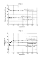
- FIG. 1 A graph showing the change in the iron loss W with the elapsed time, in the case of applying a powder magnetic core to the reactor core on which potting is not carried out.
- FIG. 2 A graph showing the breakdown (eddy current loss W e and hysteresis loss W h ) of iron loss W of the powder magnetic core shown in FIG. 1 .
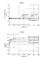
- FIG. 3 A graph showing the changes in the effective magnetic permeability ⁇ a with the elapsed time, of the powder magnetic cores A to C in Example.
- FIG. 4 A graph showing the changes in the hysteresis loss W h with the elapsed time, of the powder magnetic cores A to C.
- FIG. 5 A graph showing the changes in the eddy current loss W e with the elapsed time, of the powder magnetic cores A to C.
- FIG. 6 A graph showing the changes in the iron loss W with the elapsed time, of the powder magnetic cores A to C.
- FIG. 7 Scanning electron micrograph images showing the state of gaps between the particles in the cross-section, respectively, of the powder magnetic cores A and C.
- FIG. 1 shows a result of examining the change in iron loss W with the elapsed time, by: configuring the reactor having as the core a powder magnetic core prepared using iron powder, Somaloy 110i(5P) manufactured by Höganäs AB Co.; allowing it in a predetermined time period to stand in a 180° C. air in a state of being not potted; and then measuring iron loss W in the frequency of 10 kHz at the magnetic flux density of 100 mT.
- the iron loss W whose initial value is about 115 kW/m 3
- the iron loss W is increasing up to about 138 kW/m 3 , i.e. 1.2 times, with the passage of the heating time.
- the iron loss of the powder magnetic core has been found to increase as time passes.
- the iron loss W can be represented by the sum of eddy current loss W e and hysteresis loss W h as shown in the formula (1) below, and the eddy current loss W e and the hysteresis loss W h can be shown by the following formula (2) and formula (3).
- f represents the frequency
- B m is the excitation magnetic flux density
- ⁇ is an intrinsic resistance value
- t is a thickness of a material
- k 1 and k 2 are coefficients.
- W W e +W h (1)
- W e ( k 1 B m 2 t 2 / ⁇ ) f 2 (2)
- W h k 2 B m 1.6 f (3)
- the eddy current loss W e is increased in proportion to the square of the thickness t of the material.
- the eddy currents are confined inside the soft magnetic power particles by forming an insulation film on the surface of each of the soft magnetic powder particles, and, at the same time, by compacting it densely, it is attempt to enhance the magnetic flux density and reduce the iron loss.
- the present inventors since the eddy current loss W e increases when the insulation is insufficient, the present inventors had considered the cause of increased iron loss in FIG. 1 as being deterioration of the insulation film due to aging and they measured the breakdown of the iron loss in the powder magnetic core. The result of the measurement is shown in FIG. 2 .
- the eddy current loss W e are stable regardless of the elapsed time and it has been found that increase with time in iron loss is due to an increase in hysteresis loss W h . Therefore, to suppress the increase of iron loss W with time, it is necessary to suppress the increase of hysteresis loss w h with time.
- the magnetic permeability ⁇ in the alternating magnetic field is equal to the slope of the magnetization curve (B-H curve) that is a relationship between the strength H of the magnetic field and the magnetic flux density B, and the hysteresis loss W h corresponds to the area in the magnetization curve.
- the present inventors can refer that those showing the magnetization curve being close to a straight line, or, those having a small change in the tangent slope of the magnetization curve (differential permeability) have small hysteresis loss W h , and that those having a small variation with time in the magnetic permeability are small in increase with time in the hysteresis loss W h .
- a powder magnetic core having a property that magnetic permeability is invariable is advantageous in suppressing the increase with time in the hysteresis loss, and a reactor can also be used in a state that the core is exposed with no potting, while the iron loss of the core does not increase with time and stable and good characteristics are exhibited.
- the powder magnetic core for a reactor of the present invention is characterized by consisting of a powder magnetic core that change with time in the magnetic permeability is 1% or less, and it can be suitably used as a core of a reactor which is used in the state that the core is exposed, without being potted in the case.
- the powder magnetic core that change with time in the magnetic permeability is 1% or less is produced by compaction-forming an insulation-coated soft magnetic powder that an insulating coating is formed on the surface of a soft magnetic powder having an iron-based composition, and the core formed is subjected to a heat treatment before providing for use.
- the content of gapping between two particles adjacent to each other of the insulation-coated iron-based soft magnetic powder is adjusted to 2% by volume or less, and then the above character is achieved.
- changes with time in the permeability is due to oxidation of the soft magnetic powder, and the gapping between two adjacent particles of the insulation-coated iron-based soft magnetic powder acts as a communication hole through which the inside of the powder magnetic core of reactor is communicated with and exposed to the external atmosphere, resulting in easy proceeding of oxidation in the soft magnetic powder.
- the volume ratio of the gapping in the three dimensional structure can be approximately measured as an area ratio of the gapping in the two-dimensional structure. Therefore, the content (volume ratio) of gapping between two particles of the power magnetic core can be determined as an area ratio of the gapping in a cross section of the powder magnetic core.
- the cross section of the powder magnetic core is mirror polished; the cross section is then observed at 3,000 times magnification with use of a Scanning Electron Microscope (SEM) or an Electron Prove Micro-Analyzer (EPMA) having the same function or the like; it is photographed by adjusting so as to fit the interface between two particles into the field of view and prevent voids (pores) surrounded by three or more particles; and the area ratio of the gapping is determined by analysis of the captured image, which can be regarded as the volume ratio of the gapping.
- image analysis software such as WinROOF produced by MITANI CORPORATION, QuickGrain Standard produced by Inotech Co., Ltd. and the like may be used to measure the area ratio of the gapping by setting the threshold to about 85 in the mode method.
- insulation-coated soft magnetic powder For the insulation-coated soft magnetic powder, the following ones can be suitably used.
- a soft magnetic powder which has a phosphoric acid-based chemical conversion coating and a silicone resin coating formed in this order on the surface thereof, wherein the phosphoric acid-based chemical conversion coating contains one or more elements selected from the group consisting of cobalt, sodium, sulfur, silicon and tungsten, and
- a soft magnetic powder having an insulating layer containing a particulate metal oxide and calcium phosphate, wherein the insulating layer formed on the surface of the powder is brought into contact with a silicone resin.
- the insulation-coated soft magnetic powder of the above 1) may be obtained as described in Japanese patent No. 4044591, and the insulation-coated soft magnetic powder of the above 2) may be obtained as described in Japanese Patent No. 4927983.
- the heat resistance of the phosphoric acid-based chemical conversion coating is improved by introduction of the elements such as cobalt, sodium, etc.
- the insulating layer belongs to the phosphate conversion coating and the strength and the like of the insulating layer is improved by introduction of the metal oxide particles.
- a green compact having a stable permeability at high magnetic field can be obtained using them.
- a silicone resin film is formed on the surface (and internal) of the insulating layer of 2).
- the insulating coating covering the soft magnetic powder is a multi-layer film having an inorganic and phosphorus acid-based coating on the inside and an organic silicone resin coating on the outside, and the phosphoric acid-based coating contains such a component as cobalt, calcium, etc. Since the silicone resin on the outside exhibits lubricity, these powders exhibit good flowability and compressibility and they can be formed into a green compact without using a so-called powder lubricant such as higher fatty acids, metal salts of higher fatty acid, hydrocarbon-based waxes and the like. This point is advantageous in suppression of the deterioration or change over time in a heated state that is due to the gapping between the powder particles in the green compact formed.
- a raw material powder into which a powder lubricant such as higher fatty acids, metal salts of higher fatty acids, hydrocarbon waxes and the like is blended is used.
- the powder lubricant particles in the compact is decomposed and gasified in the heat treatment process. That is, particles of the powder lubricant located between the insulation-coated iron-based soft magnetic powder particles are lost, and gap is formed between two adjacent particles of the insulation-coated iron-based soft magnetic powder.
- the gas generated from the powder lubricant particles is expanded to push the gap and escape from the compact to the outside, whereby a communication hole is formed to communicate the interior of the compact to the outside.
- the powder lubricant is given by coating it on the surface of the insulation-coated iron-based soft magnetic powder, instead of adding it in the form of a powder, the gap and the communication hole are similarly formed by the decomposition gasification of the powder lubricant.
- the powder magnetic core is formed of only the insulation-coated iron-based soft magnetic powder without using a heat-decomposable powder lubricant such as described above, formation of gap and communication hole is avoided. Therefore, it is possible to suppress the change with time in the magnetic properties caused by the internal oxidation or deterioration in the heated state.
- a raw material containing no powder lubricant and comprising only the insulation-coated iron-based soft magnetic powder is used to be formed by compaction and subjected to the heat treatment. If blending the heat decomposable powder lubricant as described above into the raw material powder, it is necessary to set the content of the powder lubricant 0.05 mass % or less.
- the galling occurs on the die during the forming by compaction with use of the above raw material powder, it is possible to prevent the die galling by forming it with application of a so-called die lubrication method that a coating film is formed by applying a die lubricant to the inner wall of the die for compaction-forming the raw material powder.
- the lubricant is deposited on the surface of the green compact formed by compaction, the green compact has no powder lubricants existing in the interior thereof. Therefore, the communication hole due to gasification of the powder lubricant is not formed inside the powder magnetic core after the heat treatment, and oxidation hardly occurs in the iron-based soft magnetic powder.
- the soft magnetic powder is a powder having a material composition whose main component is iron and being conventionally used in the manufacture of powder magnetic cores, that is, a powder of pure iron or iron alloy.
- a powder of pure iron or iron alloy for example, iron powder, Fe—Al alloy powder, silicon steel powder, sendust powder, amorphous powder, permendur powder, soft ferrite powder, permalloy powder, amorphous magnetic alloy powder, nano-crystal magnetic alloy powder and the like are mentioned for the soft magnetic powder.
- It may comprise a modifying element such as aluminum, nickel, cobalt and the like, and inevitable mount of impurities (carbon, sulfur, chromium, oxygen, manganese, etc.).
- the soft magnetic powder is not particularly limited and it may be any of pulverized powder, water atomized powder, gas atomization powder, gas water atomized powder and the like.
- Gas atomized powder that is easily obtained in a powder form close to the spherical shape is preferred in view of easiness to suppress the damage of particles during forming the compact.
- a soft magnetic powder having a particle size in the range of 1 to 300 ⁇ m, preferably having an average particle diameter (by laser diffraction scattering method) of about 50 to 150 ⁇ m is used.
- the soft magnetic powder is coated with a phosphoric acid-based coating by chemical treatment with an aqueous treatment liquid composed mainly of orthophosphoric acid.
- an aqueous treatment liquid composed mainly of orthophosphoric acid.
- it can be carried out according to the literature referred for the formation of phosphoric acid-based chemical coating and a silicone resin coating on the surface of the soft magnetic powder.
- known techniques relating to phosphating treatment of metal powders for example, Japanese Patent No. 2710152, Japanese Patent Application Laid-Open No. 2005-213621, etc.
- the elements of cobalt, sodium, sulfur, silicon, tungsten and the like can be introduced into the coating by incorporating them into the aqueous treatment liquid in the form of a phosphate compound.
- an aqueous solution containing calcium ions, an aqueous phosphoric acid solution and a soft magnetic powder are combined and the pH is adjusted to basic in the mixed state, whereby calcium phosphate is deposited on the surface of the soft magnetic powder.
- the insulating layer formed on the soft magnetic powder contains the metal oxide particles and calcium phosphate.
- the metal oxide one having a particle size of about 10 to 50 nm, preferably about 10 to 100 nm, and more preferably about 10 to 50 nm is used.
- the thickness of the phosphoric acid-based coating it may be adjusted by the formulation and the amount of the treatment liquid used.
- the phosphoric acid-based coating is a good insulating film having the function of suppressing the oxidation of the soft magnetic powder, and it further serves to combine the silicone resin and the soft magnetic powder. Silicone resin is difficult to bond directly to the soft magnetic powder due to its low affinity for the metal, but it is capable of coating the soft magnetic powder through the phosphorus acid-based coating since it has an affinity or binding nature for a polar substance such a phosphoric acid compounds and metal oxides.
- an organic solvent solution of the curable silicone resin is applied and then dried, whereby silicone resin coating film is formed on the powder surface. Furthermore, the resin coating film is cured by condensation of the hydroxyl groups therein, whereby it becomes a silicone resin film insoluble in a solvent.
- the organic solvent of the silicone resin solution may be any one capable of dissolving the silicone resin and it may be selected as needed from those conventionally used in the preparation of a silicone resin solution. Drying of the powder coated with the resin solution is to proceed by heating to a temperature at which the organic solvent is volatilized, and a temperature of about 60 to 80° C. can be generally applied in the case of alcohol or petroleum-based organic solvent.
- Drying is possibly facilitated by air drying or vacuum. Since curing of the silicone resin coating film proceeds by heating to about 100 to 250° C., drying and curing can be performed simultaneously or in succession in one step if the temperature at the time of drying is set in the range of the curing temperature.
- the curable silicone resin which is applied to the insulation-coated soft magnetic powder is a condensation product of silanols (containing tri-functional or tetra-functional silanol) produced by hydrolysis of a hydrolysable silane compound (chlorosilanes, etc.), that is, a polysiloxane, and it has a structural unit of polydimethylsiloxane type, polymethylphenylsiloxane type, polydiphenylsiloxane type or the like, depending on the substituent bonded to the silicon of the silanol.
- silanols containing tri-functional or tetra-functional silanol
- a condensate of silanol product in which the proportion of tri-functional silanol is about 60 mol % or more, and preferably about 80 mol % or more (the balance bi-functional silanol) can be used as the silicone resin in the present invention.
- the number of methyl groups is large, the volume reduction ratio by compression of the silicone resin is large.
- the ratio of methyl groups to phenyl groups in the substituents bonded to silicon is preferably about 4:6 to 8:2.
- the molecular weight Mw of about 2,000 to 200,000 and the hydroxyl value of about 1 to 5% by mass may be well.
- Curing of the silicone resin is to form a crosslink with a siloxy bond by the condensation of hydroxyl groups bonded to the silicon, and the resin is suitably cured by heating it at about 100 to 250° C. for about 5 to 100 minutes. Intermolecular distance in the silicone resin is longer than those in the carbon-based resins, and it is so easy to cause volume shrinkage by curing. Thus, with this in mind, it is appropriate to adjust the amount of the resin solution to be applied, so that a thickness of the silicone resin coating film after the curing is about 10 to 500 nm, preferably 20 to 200 nm.
- the total thickness of these films is set to be 50 nm or more.
- the insulating film is formed on the surface of the soft magnetic so as to have a film thickness of at least 50 nm, whereby the insulation is ensured even at the thinnest portion.
- the sum of the film thickness of the phosphoric acid-based coating and the film thickness of the silicone resin coating is set to be about 1,500 nm or less. It is noted that there is a tendency that the hydroxyl groups in the silicone resin are not completely fit the condensation in the thermal curing and unreacted hydroxyl groups may remain. In particular, a hydroxyl group in the outer surface of the cured resin may remain. As the reason, it is conceivable that, since the constituents of the above-described phosphoric acid-based film can act catalytically to the silicone resin, heat-curing of the silicone resin easily proceeds toward the outer surface from the contact interface with the phosphoric acid-based film. If this tendency is remarkable, the hardness in the cured silicone resin film is higher at the inside than that of the outer circumferential side.
- the insulation-coated soft magnetic powder obtained by forming the silicone resin coating is received in the die and is then compacted by pressing at a contact pressure of about 400 to 2,000 MPa to form a green compact so that surface factor of the soft magnetic powder (calculated as a density ratio to the true density) is about 90% or more.
- the soft magnetic powder is iron powder
- the space factor of the soft magnetic powder can be 90% or higher if the density of the green compact is about 7.0 g/cm 3 or more.
- the density of the green compact is set to be 7.2 g/cm3 or higher, the space factor of the soft magnetic powder is 92% or higher and that is thus preferable.
- the compacting may be done by any of cold pressing and hot pressing. If hot pressing is performed by heating to approximately 100 to 250° C., it is possible to relax the compressive strain at the pressing time and the hot pressing at the above temperature is thus effective to obtain a compact which is small in hysteresis loss. Since the powder coated with a silicone resin film has good fluidity, powder lubricants like metal soaps and fatty acids such as waxes are not required in the compacting.
- the surface of the soft magnetic powder is coated with the phosphoric acid-based film and the silicone resin coating
- the phosphoric acid-based film and the silicone resin coating ones provided commercially may be used and they include, for example, the powders MH20D, MH23D and MH45D manufactured by Kobe Steel Ltd., and the like.
- the green compact formed is subjected to heat treatment (annealing) in order to reduce the hysteresis loss due to compressive strain.
- the compact which has undergone the heat treatment is a powder magnetic core usable as a reactor core.
- crystal grains of the soft magnetic powder are coarsened.
- the temperature of the heat treatment may be about 400 to 800° C., preferably about 600 to 700° C.
- the treatment time may be about 1 to 300 minutes, preferably about 10 to 60 minutes.
- the heat treatment is preferably carried out under a non-oxidizing environment and it may be performed, for example, under vacuum or in an inert gas atmosphere such as hydrogen, nitrogen, argon and the like.
- the cooling rate after the heat treatment is desirably about 2 to 20/min, so as not to cause the refining of crystal grains.
- the hydroxyl groups remaining in the silicone resin film are capable of reacting.
- condensation reaction is likely to proceed to form a crosslinking bond between the silicone resin coating films, which contributes to improving the strength of the compact.
- the organic carbon compounds such as fatty acids and hydrocarbons are ready to be thermally decomposed in the temperature range for the heat treatment of the above green compact, in the case of using a lubricant such as waxes and metallic soaps, it is decomposed and burned so that it does not remain almost throughout the compact. Condensation reaction between the silicone resin films is not inhibited, either. Therefore, when using the compact which has undergone the heat treatment as a reactor core, change due to the lubricant does not occur even if the temperature is raised to about 150° C., and it does not become a growth factor of hysteresis loss. Space factor of the soft magnetic powder in the compact after the heat treatment is maintained to the value before the heat treatment, and it is at least about 90%.
- the eddy current loss is not involved in the increase with time in the iron loss when used as a reactor core, increase of hysteresis loss is not due to such a change as reducing in the electrical resistance of the insulation coating, but is related to the factor which may affect the soft magnetic powder particles.
- the effect of the present invention is considered to be an effect by inhibiting such a factor.
- the factor affecting the soft magnetic powder there are mentioned deterioration of the soft magnetic powder (iron) by oxidation, invasion of impurities and change in the grain boundary (graining).
- oxygen in the atmosphere coming into contact through cracks that may occur in the insulation coating at the time of compacting, and oxygen constituting the phosphoric acid-based coating film, are considered as oxygen source of the oxidation.
- an oxidizable component contained in the phosphoric acid-based coating film is considered as one of the oxidation suppressing elements for the soft magnetic powder.
- the components such as cobalt, sodium, sulfur, tungsten, silicon, calcium and the like stabilize the phosphoric acid in the phosphate coating as well as they are oxidizable, they prevent the oxygen constituting the phosphoric acid from migrating to the soft magnetic powder by a temperature rise and are also capable of scavenging the oxygen coming from the outside to suppress the direct oxidation of the soft magnetic powder.
- the silicone resin has high heat resistance in general as compared with the resin of the organic carbon compound type and has sufficient durability against the temperature rise at the time of use so as to maintain the insulating properties, metal oxides may act catalytically to the silicone resin and it becomes easy to produce silicon dioxide in the vicinity of the resin surface in a high temperature during the heat treatment.
- the phosphoric acid-based coating film becomes reducible trend and indirectly inhibits the oxidation of the neighboring soft magnetic powder.
- the silicone resin coating film has a sufficient thickness.
- the silicone resin coating film having a thickness of approximately 10 nm or more is suitable.
- the gap between the powder particles when the gap between the powder particles is large, it facilitates the supply by intrusion of the oxygen in the atmosphere and reactions are possibly promoted over time. Therefore, the issue of possibly reducing the gap between the powder particles is important for maintaining the heat resistance of the compact.
- the contact between the silicone resins since the contact between the silicone resins has a very good lubricity so that the insulation-coated soft magnetic powder is easily compressed to high density, the powder particles in the compact obtained according to the above are in close contact with each other and have less clearance. Then the adhesion is also formed between the silicone resin coatings. Therefore, even if the temperature is raised to about 150° C.
- a compact stable in the magnetic permeability such that change with time (500 hours) of the effective magnetic permeability at 180° C. is about 3% or less, in particular about 1% or less, is provided and it shows a preferred electromagnetic properties as a powder magnetic core for a reactor. That is, in the powder magnetic core used as the reactor core, the coercive force is hardly changed even when the temperature rises, and increases with time in the hysteresis loss and iron loss can be suppressed.
- the insulation-coated iron-based soft magnetic powder provided was a commercially available powder MH20D (manufactured by Kobe Steel, Ltd.).
- the powder MH20D is a powder according to Japanese Patent No. 4,044,591, that is an iron-based soft magnetic powder having a phosphoric acid-based chemical film and a silicone resin coating film formed in this order on the surface thereof (main particle fraction in the particle size distribution: 45 to 75 ⁇ m), wherein the above phosphoric acid-based chemical conversion film contains one or more elements selected from the group consisting of cobalt, sodium, sulfur, silicon and tungsten.
- the powder does not contain a kind of powder lubricant.
- the insulation-coating layer made of the above phosphoric acid-based chemical film and the silicone resin film is formed relatively uniform on the surface of the iron-based soft magnetic powder, and the film thickness in the thinnest portion of the insulation coating layer is about 50 nrn.
- the powder MH20D was compacted at a compacting pressure of 1,200 MPa to prepare a green compact (density: 7.4 g/cm 3 ) of a ring shape having an outer diameter of 30 mm, an inner diameter of 20 mm and a height of 5 mm. After the compacting, heat treatment was performed by heating it to 600° C. to obtain a powder magnetic core A.
- the insulation-coated iron-based soft magnetic powder prepared was a powder of the category of Japanese Patent 4,927,983, that was an iron-based soft magnetic powder with an insulation layer containing a particulate metal oxide and calcium phosphate and being coated with a silicone resin.
- This powder does not contain a kind of powder lubricant, either.
- the insulation coating layer made of the insulation layer containing particulate metal oxide and calcium phosphate and of the silicone resin coat were formed unevenly on the surface of the iron-based soft magnetic powder, and the thickness of the insulation coating layer in the thinnest portion thereof was about 70 nm.
- the powder was compacted at a compacting pressure of 1,480 MPa to prepare a green compact (density: 7.4 g/cm 3 ) of a ring shape having an outer diameter of 30 mm, an inner diameter of 20 mm and a height of 5 mm. After the compacting, heat treatment was performed by heating it to 600° C. to obtain a powder magnetic core B.
- a powder, Somaloy 110i(5P) (main particle fraction in the particle size distribution: 106 to 150 ⁇ m) manufactured by Höganäs AB, was prepared as the commercially available iron-based soft magnetic powder being insulation-coated with phosphoric acid-based chemical conversion film. It is noted that the powder had contained a powder lubricant (ethylene-bis-stearic acid amide) and the surface of the phosphoric acid-based chemical film had been coated with the powder lubricant component.
- the above-described insulation coating layer made of the phosphoric acid-based chemical film and the powder lubricant component had been formed non-uniformly on the surface of the iron-based soft magnetic powder, and the thickness of the insulation coating layer was approximately 20 nm in the thinnest portion thereof.
- the powder was compacted at a compacting pressure of 1,200 MPa to prepare a green compact (density: 7.4 g/cm 3 ) of a ring shape having an outer diameter of 30 mm, an inner diameter of 20 mm and a height of 5 mm. After the compacting, heat treatment was performed by heating it to 600° C. to obtain a powder magnetic core C.
- the cross section of the powder magnetic core was mirror polished.
- the cross section of the powder magnetic core was observed, respectively, at 3,000-fold magnification by means of EPMA, and the state of gapping between the powder particles was photographed.
- WinROOF produced by MITANI CORPORATION
- the area ratio of gapping in the respective powder magnetic core was measured by setting the threshold to 85 in the mode method.
- the content of gapping between two powder particles, as an area ratio was 0.7% for the powder magnetic core A, 1.0% for the powder magnetic core B, and 8.5% for the powder magnetic core C, respectively.
- each of the powder magnetic cores A, B and C prepared in the above as a core was wound with a coil and allowed directly to stand in an atmosphere (air) heated to 180° C., without performing the potting.
- the effective magnetic permeability ⁇ a , the eddy current loss W e and the hysteresis loss W h were measured with time at frequency of 10 kHz and magnetic flux density of 100 mT, and the iron loss W was calculated. From the obtained values, the relationship between each of the items and the elapsed time was examined, respectively. The results are shown in FIG. 3 to FIG. 6 .
- the initial effective magnetic permeability ⁇ a is 217 and high, the effective magnetic permeability ⁇ a is decreased with the elapsed time to about 206, that is, the decreasing ratio (the ratio of the decreasing amount to the initial value) is about 5%.
- the initial effective magnetic permeability ⁇ a is about 154, and decrease in effective magnetic permeability ⁇ a with time is small and the decreasing ratio is about 1%.
- the initial effective magnetic permeability ⁇ a is about 144, and decrease in effective magnetic permeability ⁇ a with time is small and the decreasing ratio is about 1%.
- the resultant values of hysteresis loss W h measured for the powder magnetic cores A to C indicating the effective magnetic permeability ⁇ a as shown in FIG. 3 are shown in FIG. 4 .
- the hysteresis loss W h which is initially about 100 kW/m 3 is increased up to about 128 kW/m 3 with the laps of time and, in other words, it has become about 1.3 times.
- the hysteresis loss W h does not increase even after the lapse of time and becomes ultimately a lower value than the powder magnetic core C.
- the eddy current loss W e in any of the powder magnetic cores A to C indicates a stable value regardless of the time elapsed.
- FIG. 7 The results of observation of the cross-section of the powder magnetic cores A and C by the scanning electron microscope are shown in FIG. 7 .
- the powder magnetic core A containing no powder lubricant almost no gapping is observed between two adjacent particles of the insulation-coated iron-based soft magnetic powder, and the void (pore) formed by three or more particles of the insulation-coated iron-based soft magnetic powder is in the state of closed pore. Therefore, the interior of the powder magnetic core A is shut off from the outside air, and oxidation of the iron-based soft magnetic powder is unlikely to proceed.
- the powder magnetic core C using the insulation-coated iron-based soft magnetic powder whose surface is coated with the powder lubricant gap is obviously formed between two adjacent particles of the insulation-coated iron-based soft magnetic powder, and the void (pore) formed by three or more particles of the insulation-coated iron-based soft magnetic powder is in the state of open pore. Therefore, in the powder magnetic core C, the gap formed between two adjacent particles of insulation-coated iron-based soft magnetic powder makes a communicating hole and the outside air is led to the inside of the powder magnetic core, so that the iron-based soft magnetic powder is in the state that oxidation easily proceeds. Therefore, it is considered that the progress of oxidation of the iron-based soft magnetic powder has resulted in the change with time in the effective magnetic permeability ⁇ a .
- the raw material powder As the raw material powder, a commercially available powder MH20D (manufactured by Kobe Steel, Ltd.), which was used in the preparation of the powder magnetic core A of the First Embodiment, was prepared, and a zinc stearate powder provided as a powder lubricant was dissolved in ethanol to prepare a powder lubricant solution.
- the raw material powder was dipped in the powder lubricant solution in such a proportion of the powder lubricant to the raw material powder as shown in Table 1, and it was stirred and allowed to volatize ethanol, whereby the surface of the raw material powder was coated with the powder lubricant.
- Table 1 a proportion of the powder lubricant to the raw material powder as shown in Table 1, and it was stirred and allowed to volatize ethanol, whereby the surface of the raw material powder was coated with the powder lubricant.
- A1 to A7 was prepared by compacting it in the manner similar to the powder magnetic core A of the First Embodiment, and the content of gapping between two powder particles was measured. Further, using each of the produced powder magnetic cores as the core, the effective magnetic permeability ⁇ a , the eddy current loss W e and the hysteresis loss W h were measured with time on the same conditions as the First Embodiment, and the iron loss W was calculated. Then the relationship between the elapsed time and the value of each item in the heated atmosphere was examined. For each of the powder magnetic cores of Sample Nos.
- the powder magnetic cores of Sample Nos. A1 to A7 contain a powder lubricant.
- the ratio of change in the effective magnetic permeability ⁇ a is a small value of ⁇ 1% in the powder magnetic core of Sample No. A3 that the amount of the powder lubricant is a trace amount of 0.05% by mass, and thus increase in the hysteresis loss W h is very small and increase of iron loss W is also quite small.
- decrease of the effective magnetic permeability ⁇ a is small in Sample No. A3 that the content of gapping between two powder particles is a small value of 2%, and decrease of the effective magnetic permeability ⁇ a is large in Sample Nos. A4 to A7 the content of gapping between two powder particles is large.
- the powder magnetic core for use of the powder magnetic core suitably as a reactor core in the state exposed to the atmosphere without potting, it is important to configure the powder magnetic core in such a manner that the ratio of decrease in the effective magnetic permeability is 1% or less, in order to suppress the increase of iron loss due to the time of use. Moreover, it is effective, for achieving the ratio of decrease in the effective magnetic permeability ⁇ a of 1% or less, to suppress 2 vol % or less the gapping content between two adjacent particles of the insulation-coated iron-based soft magnetic powder in the green compact. This item can be approximated as the gapping content between two powder particles in a cross section that is 2 area % or less.
- the powder magnetic core configured as described above is thus a ready-to-use powder magnetic core for a reactor without potting, and it is to suitably function as the core of the reactor in the state exposed to the atmosphere.
- a powder magnetic core which shows good magnetic properties in the high frequency range is provided, and it exhibits superior performance when used as a core of a booster circuit such as a reactor, an ignition coil and the like, or of a circuit used in a high magnetic field and in a high frequency range, such as a choke coil, a noise filter and the like. It contributes to improving the performance of various products for high frequency and also supports the use in the range of a commercial frequency to medium frequency, such as electrical components and automotive or general industrial motor core, thereby enabling the supply of highly versatile products.
Landscapes
- Engineering & Computer Science (AREA)
- Power Engineering (AREA)
- Physics & Mathematics (AREA)
- Spectroscopy & Molecular Physics (AREA)
- Chemical & Material Sciences (AREA)
- Dispersion Chemistry (AREA)
- Manufacturing & Machinery (AREA)
- Soft Magnetic Materials (AREA)
- Powder Metallurgy (AREA)
Abstract
Description
W=W e +W h (1)
W e=(k 1 B m 2 t 2/ρ)f 2 (2)
Wh=k2Bm 1.6f (3)
| TABLE 1 | |||||
| Effective magnetic | |||||
| Lubricant | Gapping | permeability μa | |||
| Sample | content | content | After lapse | Ratio of | ||
| No. | mass % | area % | Initial | of 528 hr | change | Remarks |
| A |
| 0 | 0.7 | 153.5 | 152.1 | −0.95 | Powder magnetic core A | |
| A1 | 0.01 | 0.9 | 153.1 | 151.6 | −0.98 | Powder magnetic core A + Lubricant |
| A2 | 0.03 | 1.2 | 153.7 | 152.2 | −0.98 | Powder magnetic core A + Lubricant |
| A3 | 0.05 | 2.0 | 152.7 | 151.2 | −1.00 | Powder magnetic core A + Lubricant |
| A4 | 0.07 | 2.1 | 152.4 | 150.1 | −1.50 | Powder magnetic core A + Lubricant |
| A5 | 0.10 | 3.7 | 151.6 | 147.5 | −2.70 | Powder magnetic core A + Lubricant |
| A6 | 0.30 | 6.9 | 152.3 | 147.0 | −3.50 | Powder magnetic core A + Lubricant |
| A7 | 0.40 | 8.7 | 151.8 | 145.0 | −4.50 | Powder magnetic core A + |
| B | ||||||
| 0 | 1.0 | 143.5 | 142.1 | −1.01 | Powder magnetic core B | |
| C | 0.40 | 8.5 | 216.6 | 206.9 | −4.47 | Powder magnetic core C |
| TABLE 2 | ||||
| Initial | After laps of 528 hr | |||
| Lubricant | Eddy current | Hysteresis | Iron | Eddy current | Hysteresis | Iron | ||
| Sample | content | loss We | loss Wh | loss W | loss We | loss Wh | loss W | |
| No. | mass % | kW/m3 | kW/m3 | kW/m3 | kW/m3 | kW/m3 | kW/m3 | Remarks |
| A | 0 | 16.1 | 119.1 | 135.1 | 16.5 | 121.7 | 138.2 | Powder magnetic core A |
| A1 | 0.01 | 16.2 | 119.3 | 135.5 | 16.4 | 121.8 | 138.2 | Powder magnetic core A + Lubricant |
| A2 | 0.03 | 16.1 | 119.4 | 135.5 | 16.5 | 121.9 | 138.4 | Powder magnetic core A + Lubricant |
| A3 | 0.05 | 16.1 | 119.6 | 135.7 | 16.5 | 122.1 | 138.6 | Powder magnetic core A + Lubricant |
| A4 | 0.07 | 16.2 | 119.4 | 135.6 | 16.4 | 125.5 | 141.9 | Powder magnetic core A + Lubricant |
| A5 | 0.10 | 16.3 | 119.4 | 135.7 | 16.4 | 130.4 | 146.8 | Powder magnetic core A + Lubricant |
| A6 | 0.30 | 16.2 | 119.5 | 135.7 | 16.4 | 142.8 | 159.2 | Powder magnetic core A + Lubricant |
| A7 | 0.40 | 16.2 | 119.6 | 135.8 | 16.4 | 150.1 | 166.5 | Powder magnetic core A + |
| B | ||||||||
| 0 | 14.7 | 110.5 | 125.2 | 14.5 | 111.7 | 126.2 | Powder magnetic core B | |
| C | 0.40 | 15.7 | 99.7 | 115.3 | 15.5 | 127.9 | 143.3 | Powder magnetic core C |
Claims (5)
Applications Claiming Priority (3)
| Application Number | Priority Date | Filing Date | Title |
|---|---|---|---|
| JP2013066018 | 2013-03-27 | ||
| JP2013-066018 | 2013-03-27 | ||
| PCT/JP2014/058857 WO2014157517A1 (en) | 2013-03-27 | 2014-03-27 | Powder magnetic core for reactor |
Publications (2)
| Publication Number | Publication Date |
|---|---|
| US20160071637A1 US20160071637A1 (en) | 2016-03-10 |
| US10074468B2 true US10074468B2 (en) | 2018-09-11 |
Family
ID=51624478
Family Applications (1)
| Application Number | Title | Priority Date | Filing Date |
|---|---|---|---|
| US14/779,138 Active 2034-11-08 US10074468B2 (en) | 2013-03-27 | 2014-03-27 | Powder magnetic core for reactor |
Country Status (5)
| Country | Link |
|---|---|
| US (1) | US10074468B2 (en) |
| JP (1) | JP6265210B2 (en) |
| CN (1) | CN105051839B (en) |
| DE (1) | DE112014001651T5 (en) |
| WO (1) | WO2014157517A1 (en) |
Cited By (2)
| Publication number | Priority date | Publication date | Assignee | Title |
|---|---|---|---|---|
| CN111435627A (en) * | 2019-01-11 | 2020-07-21 | 京瓷株式会社 | Core member, method of manufacturing core member, and inductor |
| US11094437B2 (en) * | 2013-03-28 | 2021-08-17 | Basf Se | Non-corrosive soft-magnetic powder |
Families Citing this family (13)
| Publication number | Priority date | Publication date | Assignee | Title |
|---|---|---|---|---|
| KR101470513B1 (en) * | 2013-07-17 | 2014-12-08 | 주식회사 아모그린텍 | Soft Magnetic Cores Having Excellent DC Biased Characteristics in High Current and Core Loss Characteristics, and Manufacturing Methods thereof |
| JP6478107B2 (en) * | 2015-03-30 | 2019-03-06 | 日立化成株式会社 | Powder magnetic core and reactor using the powder magnetic core |
| JP6443269B2 (en) * | 2015-09-01 | 2018-12-26 | 株式会社村田製作所 | Magnetic core and manufacturing method thereof |
| EP3387701A4 (en) * | 2015-12-08 | 2019-06-19 | 3M Innovative Properties Company | Magnetic isolator, method of making the same, and device containing the same |
| JP6256635B1 (en) * | 2017-01-16 | 2018-01-10 | Tdk株式会社 | Inductor element and method of manufacturing inductor element |
| JP2021086990A (en) * | 2019-11-29 | 2021-06-03 | 株式会社タムラ製作所 | Reactor |
| JP7494608B2 (en) * | 2020-07-08 | 2024-06-04 | 株式会社レゾナック | Powder magnetic core and manufacturing method thereof |
| CN112530654B (en) * | 2020-12-04 | 2023-09-26 | 安徽中马磁能科技股份有限公司 | A kind of sintered permanent magnet ferrite and its forming method |
| JP7529595B2 (en) * | 2021-03-10 | 2024-08-06 | 株式会社トーキン | Powder core, inductor, and method for manufacturing powder core |
| JP2022156382A (en) * | 2021-03-31 | 2022-10-14 | 株式会社タムラ製作所 | Reactor |
| DE102021203308A1 (en) | 2021-03-31 | 2022-10-06 | Universität Stuttgart, Körperschaft Des Öffentlichen Rechts | Process for manufacturing an electrical component |
| CN113223843B (en) * | 2021-04-25 | 2022-12-20 | 宁波中科毕普拉斯新材料科技有限公司 | Insulation coating method of composite soft magnetic powder |
| JP7783008B2 (en) * | 2021-10-14 | 2025-12-09 | 株式会社神戸製鋼所 | Iron-based sintered body and method for producing the same |
Citations (29)
| Publication number | Priority date | Publication date | Assignee | Title |
|---|---|---|---|---|
| JPS4927983B1 (en) | 1970-12-29 | 1974-07-23 | ||
| US5160447A (en) * | 1988-02-29 | 1992-11-03 | Kabushiki Kaisha Sankyo Seiki Seisakusho | Compressed powder magnetic core and method for fabricating same |
| JPH06260319A (en) | 1993-03-08 | 1994-09-16 | Kobe Steel Ltd | Dust core for high frequency and manufacture thereof |
| US5449419A (en) * | 1990-04-24 | 1995-09-12 | Alps Electric Co., Ltd. | Fe based soft magnetic alloy, magnetic materials containing same, and magnetic apparatus using the magnetic materials |
| JPH09102409A (en) | 1995-10-02 | 1997-04-15 | Hitachi Ltd | Dust core resin composition, dust core, reactor, and electric equipment using the same |
| JPH10189323A (en) | 1996-12-25 | 1998-07-21 | Matsushita Electric Ind Co Ltd | Dust core and manufacturing method thereof |
| US6083325A (en) * | 1996-07-15 | 2000-07-04 | Alps Electric Co., Ltd. | Method for making Fe-based soft magnetic alloy |
| JP2000312484A (en) | 1999-04-23 | 2000-11-07 | Matsushita Electric Works Ltd | Solar power generating device |
| JP2005072198A (en) | 2003-08-22 | 2005-03-17 | Toyota Motor Corp | Reactor noise reduction method and apparatus |
| CN1615528A (en) | 2002-01-17 | 2005-05-11 | Nec东金株式会社 | Powder magnetic core and HF reactor therewith |
| JP2005213621A (en) | 2004-01-30 | 2005-08-11 | Sumitomo Electric Ind Ltd | Soft magnetic material and dust core |
| CN1783370A (en) | 2004-12-03 | 2006-06-07 | 丰田自动车株式会社 | Noise reducing method and device for reactor |
| JP2007059656A (en) | 2005-08-25 | 2007-03-08 | Sumitomo Electric Ind Ltd | Soft magnetic material, dust core, method for producing soft magnetic material, and method for producing dust core |
| JP2007211340A (en) | 2006-01-12 | 2007-08-23 | Sumitomo Electric Ind Ltd | Soft magnetic material, dust core, method for producing soft magnetic material, and method for producing dust core |
| JP4004591B2 (en) | 1997-04-18 | 2007-11-07 | オリンパス株式会社 | Camera with self-mode function |
| JP4044591B1 (en) | 2006-09-11 | 2008-02-06 | 株式会社神戸製鋼所 | Iron-based soft magnetic powder for dust core, method for producing the same, and dust core |
| JP2008231443A (en) | 2007-03-16 | 2008-10-02 | Kobe Steel Ltd | Powder for dust core, dust core and method for producing the same |
| US20090226751A1 (en) * | 2006-09-11 | 2009-09-10 | Kabushiki Kaisha Kobe Seiko Sho (Kobe Steel Ltd.) | Powder core and iron-base powder for powder core |
| JP2009231495A (en) | 2008-03-21 | 2009-10-08 | Toyota Motor Corp | Reactor |
| US20100060539A1 (en) * | 2008-09-08 | 2010-03-11 | Tomohiro Suetsuna | Core-shell magnetic material, method of manufacturing core-shell magnetic material, device, and antenna device |
| WO2011118774A1 (en) | 2010-03-26 | 2011-09-29 | 日立粉末冶金株式会社 | Dust core and method for producing same |
| JP2011233860A (en) | 2010-04-09 | 2011-11-17 | Hitachi Chem Co Ltd | Dust core and manufacturing method thereof |
| US20120038532A1 (en) * | 2009-03-27 | 2012-02-16 | Kabushiki Kaisha Toshiba | Core-shell magnetic material, method for producing core-shell magnetic material, device, and antenna device |
| JP2012134244A (en) | 2010-12-20 | 2012-07-12 | Kobe Steel Ltd | Manufacturing method of dust core, and dust core obtained by the same |
| WO2012115137A1 (en) | 2011-02-22 | 2012-08-30 | 三菱マテリアル株式会社 | Composite soft magnetic material having low magnetic strain and high magnetic flux density, method for producing same, and electromagnetic circuit component |
| CN102693826A (en) | 2011-03-24 | 2012-09-26 | 阿尔卑斯绿色器件株式会社 | Powder magnetic core and manufacturing method thereof |
| US20130228716A1 (en) * | 2011-08-31 | 2013-09-05 | Kabushiki Kaisha Toshiba | Magnetic material, method for producing magnetic material, and inductor element |
| US20130342069A1 (en) * | 2012-06-21 | 2013-12-26 | Toyota Motor Engineering & Manufacturing Na | Iron oxide and silica magnetic core |
| US20160293309A1 (en) * | 2015-03-30 | 2016-10-06 | Hitachi Chemical Company, Ltd. | Powder magnetic core and reactor using the same |
-
2014
- 2014-03-27 WO PCT/JP2014/058857 patent/WO2014157517A1/en not_active Ceased
- 2014-03-27 CN CN201480018463.9A patent/CN105051839B/en active Active
- 2014-03-27 DE DE112014001651.9T patent/DE112014001651T5/en active Pending
- 2014-03-27 JP JP2015508695A patent/JP6265210B2/en active Active
- 2014-03-27 US US14/779,138 patent/US10074468B2/en active Active
Patent Citations (38)
| Publication number | Priority date | Publication date | Assignee | Title |
|---|---|---|---|---|
| JPS4927983B1 (en) | 1970-12-29 | 1974-07-23 | ||
| US5160447A (en) * | 1988-02-29 | 1992-11-03 | Kabushiki Kaisha Sankyo Seiki Seisakusho | Compressed powder magnetic core and method for fabricating same |
| US5449419A (en) * | 1990-04-24 | 1995-09-12 | Alps Electric Co., Ltd. | Fe based soft magnetic alloy, magnetic materials containing same, and magnetic apparatus using the magnetic materials |
| JPH06260319A (en) | 1993-03-08 | 1994-09-16 | Kobe Steel Ltd | Dust core for high frequency and manufacture thereof |
| JPH09102409A (en) | 1995-10-02 | 1997-04-15 | Hitachi Ltd | Dust core resin composition, dust core, reactor, and electric equipment using the same |
| US6083325A (en) * | 1996-07-15 | 2000-07-04 | Alps Electric Co., Ltd. | Method for making Fe-based soft magnetic alloy |
| JPH10189323A (en) | 1996-12-25 | 1998-07-21 | Matsushita Electric Ind Co Ltd | Dust core and manufacturing method thereof |
| JP4004591B2 (en) | 1997-04-18 | 2007-11-07 | オリンパス株式会社 | Camera with self-mode function |
| JP3575328B2 (en) | 1999-04-23 | 2004-10-13 | 松下電工株式会社 | Solar power generator |
| JP2000312484A (en) | 1999-04-23 | 2000-11-07 | Matsushita Electric Works Ltd | Solar power generating device |
| CN1615528A (en) | 2002-01-17 | 2005-05-11 | Nec东金株式会社 | Powder magnetic core and HF reactor therewith |
| JP2005072198A (en) | 2003-08-22 | 2005-03-17 | Toyota Motor Corp | Reactor noise reduction method and apparatus |
| JP2005213621A (en) | 2004-01-30 | 2005-08-11 | Sumitomo Electric Ind Ltd | Soft magnetic material and dust core |
| CN1783370A (en) | 2004-12-03 | 2006-06-07 | 丰田自动车株式会社 | Noise reducing method and device for reactor |
| JP2007059656A (en) | 2005-08-25 | 2007-03-08 | Sumitomo Electric Ind Ltd | Soft magnetic material, dust core, method for producing soft magnetic material, and method for producing dust core |
| CN101053047A (en) | 2005-08-25 | 2007-10-10 | 住友电气工业株式会社 | Soft magnetic material, powder magnetic core, method for manufacturing soft magnetic material, and method for manufacturing powder magnetic core |
| JP2007211340A (en) | 2006-01-12 | 2007-08-23 | Sumitomo Electric Ind Ltd | Soft magnetic material, dust core, method for producing soft magnetic material, and method for producing dust core |
| WO2008032503A1 (en) | 2006-09-11 | 2008-03-20 | Kabushiki Kaisha Kobe Seiko Sho | Iron-based soft magnetic powder for dust core, method for producing the same and dust core |
| JP4044591B1 (en) | 2006-09-11 | 2008-02-06 | 株式会社神戸製鋼所 | Iron-based soft magnetic powder for dust core, method for producing the same, and dust core |
| JP2008063651A (en) * | 2006-09-11 | 2008-03-21 | Kobe Steel Ltd | Iron-based soft magnetic powder for dust core, method for producing the same, and dust core |
| CN101479062A (en) | 2006-09-11 | 2009-07-08 | 株式会社神户制钢所 | Iron-based soft magnetic powder for dust core, method for producing same, and dust core |
| US20090226751A1 (en) * | 2006-09-11 | 2009-09-10 | Kabushiki Kaisha Kobe Seiko Sho (Kobe Steel Ltd.) | Powder core and iron-base powder for powder core |
| US20100051851A1 (en) * | 2006-09-11 | 2010-03-04 | Kabushiki Kaisha Kobe Seiko Sho (Kobe Steel, Ltd.) | Iron-based soft magnetic powder for dust core, method for producing the same and dust core |
| JP2008231443A (en) | 2007-03-16 | 2008-10-02 | Kobe Steel Ltd | Powder for dust core, dust core and method for producing the same |
| JP2009231495A (en) | 2008-03-21 | 2009-10-08 | Toyota Motor Corp | Reactor |
| US20100060539A1 (en) * | 2008-09-08 | 2010-03-11 | Tomohiro Suetsuna | Core-shell magnetic material, method of manufacturing core-shell magnetic material, device, and antenna device |
| US20120038532A1 (en) * | 2009-03-27 | 2012-02-16 | Kabushiki Kaisha Toshiba | Core-shell magnetic material, method for producing core-shell magnetic material, device, and antenna device |
| WO2011118774A1 (en) | 2010-03-26 | 2011-09-29 | 日立粉末冶金株式会社 | Dust core and method for producing same |
| CN102822913A (en) | 2010-03-26 | 2012-12-12 | 日立粉末冶金株式会社 | Dust core and method for producing same |
| JP2011233860A (en) | 2010-04-09 | 2011-11-17 | Hitachi Chem Co Ltd | Dust core and manufacturing method thereof |
| CN102834208A (en) | 2010-04-09 | 2012-12-19 | 日立化成工业株式会社 | Powder magnetic core and process for production thereof |
| US20130056674A1 (en) * | 2010-04-09 | 2013-03-07 | Takashi Inagaki | Powder magnetic core and process for production thereof |
| JP2012134244A (en) | 2010-12-20 | 2012-07-12 | Kobe Steel Ltd | Manufacturing method of dust core, and dust core obtained by the same |
| WO2012115137A1 (en) | 2011-02-22 | 2012-08-30 | 三菱マテリアル株式会社 | Composite soft magnetic material having low magnetic strain and high magnetic flux density, method for producing same, and electromagnetic circuit component |
| CN102693826A (en) | 2011-03-24 | 2012-09-26 | 阿尔卑斯绿色器件株式会社 | Powder magnetic core and manufacturing method thereof |
| US20130228716A1 (en) * | 2011-08-31 | 2013-09-05 | Kabushiki Kaisha Toshiba | Magnetic material, method for producing magnetic material, and inductor element |
| US20130342069A1 (en) * | 2012-06-21 | 2013-12-26 | Toyota Motor Engineering & Manufacturing Na | Iron oxide and silica magnetic core |
| US20160293309A1 (en) * | 2015-03-30 | 2016-10-06 | Hitachi Chemical Company, Ltd. | Powder magnetic core and reactor using the same |
Non-Patent Citations (9)
| Title |
|---|
| Abstract of JP 2008-063651 A (pub. 2008). * |
| Abstract of WO 2011-126119 A1 (publ. 2011). * |
| Form PCT/ISA/237. |
| Japanese office action dated Oct. 10, 2017 for counterpart Japanese application with English translation. |
| Machine Translation of JP 4927983 A. (Year: 2012). * |
| Office Action dated Jun. 27, 2016 issued in corresponding to Chinese Application No. 201480018463.9. |
| Official Action dated Feb. 28, 2017 in corresponding the counterpart Chinese Patent Application No. 201480018463.9. |
| Official Action dated Jan. 10, 2017 in counterpart Japanese Application. |
| The Notification of the Third Office Action dated Aug. 31, 2017 corresponding to Chinese application No. 201480018463.9. |
Cited By (3)
| Publication number | Priority date | Publication date | Assignee | Title |
|---|---|---|---|---|
| US11094437B2 (en) * | 2013-03-28 | 2021-08-17 | Basf Se | Non-corrosive soft-magnetic powder |
| CN111435627A (en) * | 2019-01-11 | 2020-07-21 | 京瓷株式会社 | Core member, method of manufacturing core member, and inductor |
| US11749441B2 (en) | 2019-01-11 | 2023-09-05 | Kyocera Corporation | Core component, method of manufacturing same, and inductor |
Also Published As
| Publication number | Publication date |
|---|---|
| WO2014157517A1 (en) | 2014-10-02 |
| US20160071637A1 (en) | 2016-03-10 |
| DE112014001651T5 (en) | 2015-12-17 |
| CN105051839B (en) | 2019-04-02 |
| JP6265210B2 (en) | 2018-01-24 |
| CN105051839A (en) | 2015-11-11 |
| JPWO2014157517A1 (en) | 2017-02-16 |
Similar Documents
| Publication | Publication Date | Title |
|---|---|---|
| US10074468B2 (en) | Powder magnetic core for reactor | |
| CN101233586B (en) | Soft magnetic material, process for production of the material, powder compressed magnetic core, and process for production of the magnetic core | |
| CN102667977B (en) | The manufacture method of reactor and reactor | |
| US6558565B1 (en) | Composite magnetic material | |
| CN102292784B (en) | Method for producing dust core | |
| JP2009228107A (en) | Iron-based soft magnetic powder for dust core, method for manufacturing the same, and dust core | |
| JP5189691B1 (en) | Iron-based soft magnetic powder for dust core, method for producing the same, and dust core | |
| EP3411169B1 (en) | Iron-based powder composition | |
| JP5257137B2 (en) | Manufacturing method of dust core | |
| JP5023041B2 (en) | Powder magnetic core and manufacturing method thereof | |
| JP4847553B2 (en) | Powder magnetic core and manufacturing method thereof | |
| JPWO2005096324A1 (en) | Soft magnetic material and dust core | |
| JP4064711B2 (en) | Powder for powder magnetic core, high-strength powder magnetic core, and production method thereof | |
| CN101142044B (en) | Iron powder coated with mg-containing oxide film | |
| CN107615411B (en) | Mixed powder for powder magnetic core and powder magnetic core | |
| JP2019096747A (en) | Powder-compact magnetic core | |
| JP4790224B2 (en) | SOFT MAGNETIC MATERIAL, ITS MANUFACTURING METHOD, AND DUST MAGNETIC CORE CONTAINING THE SOFT MAGNETIC MATERIAL | |
| JP2011129857A (en) | Method of manufacturing dust core and dust core obtained by the method | |
| EP1675137A1 (en) | Process for producing soft magnetism material, soft magnetism material and powder magnetic core | |
| US11699542B2 (en) | Dust core | |
| US20090220372A1 (en) | Low Magnetostrictive Body and Dust Core Using the Same | |
| JP2011114331A (en) | Method of manufacturing dust core, and dust core obtained by the manufacturing method | |
| JP4723609B2 (en) | Dust core, dust core manufacturing method, choke coil and manufacturing method thereof | |
| WO2011040568A1 (en) | Process for producing dust core | |
| JP2006324612A (en) | Composite soft magnetic material consisting of deposited oxide film-coated iron/silicon powder and sintered green compact of its powder |
Legal Events
| Date | Code | Title | Description |
|---|---|---|---|
| AS | Assignment |
Owner name: HITACHI CHEMICAL COMPANY, LTD., JAPAN Free format text: ASSIGNMENT OF ASSIGNORS INTEREST;ASSIGNORS:INAGAKI, TAKASHI;ISHIHARA, CHIO;NAKAYAMA, NORIYUKI;REEL/FRAME:046571/0628 Effective date: 20180719 |
|
| STCF | Information on status: patent grant |
Free format text: PATENTED CASE |
|
| MAFP | Maintenance fee payment |
Free format text: PAYMENT OF MAINTENANCE FEE, 4TH YEAR, LARGE ENTITY (ORIGINAL EVENT CODE: M1551); ENTITY STATUS OF PATENT OWNER: LARGE ENTITY Year of fee payment: 4 |
|
| AS | Assignment |
Owner name: SHOWA DENKO MATERIALS CO., LTD., JAPAN Free format text: CHANGE OF NAME;ASSIGNOR:HITACHI CHEMICAL COMPANY, LTD.;REEL/FRAME:062917/0865 Effective date: 20201001 |
|
| AS | Assignment |
Owner name: RESONAC CORPORATION, JAPAN Free format text: CHANGE OF NAME;ASSIGNOR:SHOWA DENKO MATERIALS CO., LTD.;REEL/FRAME:062946/0125 Effective date: 20230101 |
|
| AS | Assignment |
Owner name: RESONAC CORPORATION, JAPAN Free format text: CHANGE OF ADDRESS;ASSIGNOR:RESONAC CORPORATION;REEL/FRAME:066599/0037 Effective date: 20231001 |
|
| MAFP | Maintenance fee payment |
Free format text: PAYMENT OF MAINTENANCE FEE, 8TH YEAR, LARGE ENTITY (ORIGINAL EVENT CODE: M1552); ENTITY STATUS OF PATENT OWNER: LARGE ENTITY Year of fee payment: 8 |