US10072996B2 - Method for determining a mass of an attached implement for a utility vehicle - Google Patents
Method for determining a mass of an attached implement for a utility vehicle Download PDFInfo
- Publication number
- US10072996B2 US10072996B2 US15/463,073 US201715463073A US10072996B2 US 10072996 B2 US10072996 B2 US 10072996B2 US 201715463073 A US201715463073 A US 201715463073A US 10072996 B2 US10072996 B2 US 10072996B2
- Authority
- US
- United States
- Prior art keywords
- implement
- angle
- link
- upper link
- vehicle
- Prior art date
- Legal status (The legal status is an assumption and is not a legal conclusion. Google has not performed a legal analysis and makes no representation as to the accuracy of the status listed.)
- Active
Links
Images


Classifications
-
- G—PHYSICS
- G01—MEASURING; TESTING
- G01L—MEASURING FORCE, STRESS, TORQUE, WORK, MECHANICAL POWER, MECHANICAL EFFICIENCY, OR FLUID PRESSURE
- G01L5/00—Apparatus for, or methods of, measuring force, work, mechanical power, or torque, specially adapted for specific purposes
- G01L5/0009—Force sensors associated with a bearing
-
- A—HUMAN NECESSITIES
- A01—AGRICULTURE; FORESTRY; ANIMAL HUSBANDRY; HUNTING; TRAPPING; FISHING
- A01B—SOIL WORKING IN AGRICULTURE OR FORESTRY; PARTS, DETAILS, OR ACCESSORIES OF AGRICULTURAL MACHINES OR IMPLEMENTS, IN GENERAL
- A01B59/00—Devices specially adapted for connection between animals or tractors and agricultural machines or implements
- A01B59/06—Devices specially adapted for connection between animals or tractors and agricultural machines or implements for machines mounted on tractors
- A01B59/069—Devices specially adapted for connection between animals or tractors and agricultural machines or implements for machines mounted on tractors with means for weighing the implement
-
- A—HUMAN NECESSITIES
- A01—AGRICULTURE; FORESTRY; ANIMAL HUSBANDRY; HUNTING; TRAPPING; FISHING
- A01B—SOIL WORKING IN AGRICULTURE OR FORESTRY; PARTS, DETAILS, OR ACCESSORIES OF AGRICULTURAL MACHINES OR IMPLEMENTS, IN GENERAL
- A01B63/00—Lifting or adjusting devices or arrangements for agricultural machines or implements
- A01B63/02—Lifting or adjusting devices or arrangements for agricultural machines or implements for implements mounted on tractors
- A01B63/10—Lifting or adjusting devices or arrangements for agricultural machines or implements for implements mounted on tractors operated by hydraulic or pneumatic means
-
- A—HUMAN NECESSITIES
- A01—AGRICULTURE; FORESTRY; ANIMAL HUSBANDRY; HUNTING; TRAPPING; FISHING
- A01B—SOIL WORKING IN AGRICULTURE OR FORESTRY; PARTS, DETAILS, OR ACCESSORIES OF AGRICULTURAL MACHINES OR IMPLEMENTS, IN GENERAL
- A01B63/00—Lifting or adjusting devices or arrangements for agricultural machines or implements
- A01B63/02—Lifting or adjusting devices or arrangements for agricultural machines or implements for implements mounted on tractors
- A01B63/10—Lifting or adjusting devices or arrangements for agricultural machines or implements for implements mounted on tractors operated by hydraulic or pneumatic means
- A01B63/102—Lifting or adjusting devices or arrangements for agricultural machines or implements for implements mounted on tractors operated by hydraulic or pneumatic means characterised by the location of the mounting on the tractor, e.g. on the rear part
- A01B63/108—Lifting or adjusting devices or arrangements for agricultural machines or implements for implements mounted on tractors operated by hydraulic or pneumatic means characterised by the location of the mounting on the tractor, e.g. on the rear part on the front part
-
- A—HUMAN NECESSITIES
- A01—AGRICULTURE; FORESTRY; ANIMAL HUSBANDRY; HUNTING; TRAPPING; FISHING
- A01B—SOIL WORKING IN AGRICULTURE OR FORESTRY; PARTS, DETAILS, OR ACCESSORIES OF AGRICULTURAL MACHINES OR IMPLEMENTS, IN GENERAL
- A01B63/00—Lifting or adjusting devices or arrangements for agricultural machines or implements
- A01B63/02—Lifting or adjusting devices or arrangements for agricultural machines or implements for implements mounted on tractors
- A01B63/10—Lifting or adjusting devices or arrangements for agricultural machines or implements for implements mounted on tractors operated by hydraulic or pneumatic means
- A01B63/11—Lifting or adjusting devices or arrangements for agricultural machines or implements for implements mounted on tractors operated by hydraulic or pneumatic means for controlling weight transfer between implements and tractor wheels
-
- A—HUMAN NECESSITIES
- A01—AGRICULTURE; FORESTRY; ANIMAL HUSBANDRY; HUNTING; TRAPPING; FISHING
- A01B—SOIL WORKING IN AGRICULTURE OR FORESTRY; PARTS, DETAILS, OR ACCESSORIES OF AGRICULTURAL MACHINES OR IMPLEMENTS, IN GENERAL
- A01B63/00—Lifting or adjusting devices or arrangements for agricultural machines or implements
- A01B63/14—Lifting or adjusting devices or arrangements for agricultural machines or implements for implements drawn by animals or tractors
- A01B63/145—Lifting or adjusting devices or arrangements for agricultural machines or implements for implements drawn by animals or tractors for controlling weight transfer between implements and tractor wheels
-
- A—HUMAN NECESSITIES
- A01—AGRICULTURE; FORESTRY; ANIMAL HUSBANDRY; HUNTING; TRAPPING; FISHING
- A01B—SOIL WORKING IN AGRICULTURE OR FORESTRY; PARTS, DETAILS, OR ACCESSORIES OF AGRICULTURAL MACHINES OR IMPLEMENTS, IN GENERAL
- A01B59/00—Devices specially adapted for connection between animals or tractors and agricultural machines or implements
- A01B59/06—Devices specially adapted for connection between animals or tractors and agricultural machines or implements for machines mounted on tractors
- A01B59/064—Devices specially adapted for connection between animals or tractors and agricultural machines or implements for machines mounted on tractors for connection to the front of the tractor
Definitions
- the present disclosure relates to a method for determining a mass of an attached implement that is articulated to a support structure of a utility vehicle.
- Coupling attached implements with defined working functions to the front end of agricultural vehicles is known in the art.
- a front powerlift for example, can be used for the coupling. It is often important to obtain information about the current status of a mass of the attached implement during vehicle operation in order to be able to control the agricultural activity better.
- respective status information regarding a determined mass is particularly relevant for attached implements having variable load materials (e.g. agents to be sprayed, fertilizer, seed) such as sprayers, fertilizer spreaders and seeders.
- variable load materials e.g. agents to be sprayed, fertilizer, seed
- the determined mass of the attached implement is a current total mass of the attached implement including the current loaded material, or a mass of the attached implement without a load material. Since the mass of the attached implement can be determined or is already known, the amount of the loaded material that has been consumed can be determined at any time during the deployment of the vehicle. From the determination of the attached implement mass, additional information can also be derived such as the dispensed mass or quantity of the loaded material per traveled distance unit (e.g. meter) of the vehicle, or a residual range of the loaded material to be dispensed.
- Such information can be derived with little data or calculation effort and can be made available to the vehicle driver or some other person responsible for the vehicle deployment in a suitable manner visually and/or acoustically (e.g., on a graphical user interface). Determining the mass and the information derived therefrom can therefore contribute to making the respective work deployment of the vehicle efficient and comfortable for the vehicle driver.
- the mass of the attached implement is determined based on physical parameters at the front powerlift that can be determined relatively easily. At least one of the following parameters determined includes:
- angles can be determined by means of suitable length sensors or distance sensors.
- angle sensors can be used.
- the angle between the upper link or lower link and a vehicle horizontal line can also be determined by means of a biaxial force sensor (force measuring pin).
- the above-mentioned path is known and need not be further determined.
- a length sensor or distance sensor can be used to determine the path.
- the force impinging on the connection between the upper link and the attached implement and acting along the upper link can be determined by means of pressure sensors in the upper link.
- this force can also be determined by means of a biaxial force sensor (force sensing pin). This biaxial force sensor is arranged at a connecting point that acts as the connection between the support structure and the upper link.
- the mass of the attached implement can be determined with a small number of sensors available as standard products and therefore cost-effectively, and with a low number of sensed physical parameters. Some of the required sensors may already be present on the vehicle for other purposes, so that the expense for determining the mass of the attached implement is further reduced in such cases.
- the angles formed relative to the vehicle horizontal line or the vehicle vertical line relate to a fixed vehicle coordinate system.
- the inclination of the support structure or the utility vehicle or the fixed vehicle coordinate system relative to the terrestrial horizontal line is taken into account here by the above-mentioned angle of inclination.
- the angle of inclination takes on values greater than zero when the utility vehicle is oriented uphill in the forward direction.
- the utility vehicle is an agricultural vehicle such as a tractor.
- the support structure is a support structure of the vehicle, e.g., a frame or other supporting parts.
- the upper link and the lower links of the powerlift are pivotably mounted on or articulated to the support structure in order to be able to transfer the respective attached implement into different positions.
- the pivotable mounting or articulation on the support structure means that the respective component is either mounted or articulated directly on the support structure itself or on a component rigidly connected to the support structure (e.g. the casing of a transmission differential block).
- the front powerlift typically effects a multipoint mounting of the attached implement on the vehicle.
- a three point hitch is provided with which the attached implement is hitched or articulated to the support structure by means of two lower links and one upper link.
- the powerlift usually contains at least one adjustable-length lifting arm in order to be able to transfer the attached implement into different positions (e.g., working position, transport position) by means of the existing lower links and upper link.
- the lift arms present on the powerlift are actuated at least in part in a manner (e.g., hydraulically or electrically) suitable for implementing lifting and lowering movements of the powerlift.
- An adjustable-length lifting arm is advantageously used to derive one or more physical parameters for determining the mass of the attached implement. This takes into account an angle that is enclosed by a vehicle vertical line and a connecting path between two operative ends of the lifting arm. This angle is determined by means of a suitable sensor system, e.g., an angle sensor.
- a pressure force acting between the two operative ends of the lifting arm is further considered for determining the mass of the attached implement.
- This pressure force can be determined either directly by means of a sensor system on this lifting arm or indirectly by means of a sensor system at some other suitable point of the powerlift.
- the sensor system includes a pressure sensor, more particularly a differential pressure sensor.
- One operative end of the adjustable-length lifting arm has an articulated connection to the support structure, while an additional operative end of the lifting arm is articulated to a link-connecting point of the lower link.
- An additional parameter for determining the mass of the attached implement can advantageously be considered in this way.
- This parameter is the length of a connecting path along the lower link between the support structure and the link-connecting point. The length of this connecting path is either already known from the data for the powerlift or is determined in a suitable manner.
- Individual or all adjustable-length lifting arms used in the powerlift are each constructed as a piston-cylinder unit and act in particular as hydraulic lifting cylinders, which can be coupled to a hydraulic control circuit in a technically simple manner.
- the determined mass of the attached implement is advantageously also used to determine data regarding the center of gravity of the attached implement. This can support a movement control of the powerlift, e.g., for a precise transfer of the attached implement into a desired target position.
- a coordinate system having an x-axis and a z-axis is defined for unambiguous determination of the center of gravity.
- the x-axis is oriented parallel to a longitudinal direction or a vehicle horizontal line of the utility vehicle and the z-axis is oriented parallel to a vertical direction or a vehicle vertical line of the vehicle, the x-axis and the z-axis intersecting in a zero point of the coordinate system.
- Suitable zero points can be the position of a rear axle of the vehicle, for example.
- the determined data for the center of gravity of the attached implement contains the x-coordinate thereof in the above-mentioned coordinate system, whereby sufficient data for a movement control of the front powerlift and for determination of the current position of the attachment can be determined in many application cases with a small algorithmic processing effort.
- the x-coordinate of the center of gravity of the attached implement is determined as a function of at least one of the following physical parameters at the powerlift:
- FIG. 1 is a schematic side view of an attached implement articulated to a front powerlift at the front end of a utility vehicle;
- FIG. 2 is a schematic representation of forces impinging on a lower link of the front powerlift according to FIG. 1 ;
- FIG. 3 is a schematic representation of forces impinging on the attached implement from FIG. 1 .
- an attached implement 10 is schematically shown articulated to the front end of a utility vehicle (such as a tractor).
- a front powerlift 12 is articulated onto a support structure 14 of the utility vehicle.
- the front powerlift 12 having an upper link 16 and two parallel lower links 18 , forms a three-point hitch for receiving the attached implement 10 .
- the upper link 16 has an articulated connection via an articulation point C to the support structure 14 and via an articulation point E to the attached implement 10 .
- the upper link 16 is arranged centrally between two parallel lower links 18 .
- Each lower link 18 has an articulated connection via an articulation point A to the support structure 14 and via an articulation point K to the attached implement 10 .
- the articulation points E, K on the attached implement are designed in the usual manner, e.g., as catch hooks for the front powerlift 12 .
- the articulation point C permits three different positions in the vertical direction 20 for articulating the upper link 16 .
- the respective position is defined by a user and accordingly installed.
- An angle ⁇ is enclosed between the upper link 16 and a vehicle horizontal line 22 .
- An angle ⁇ is enclosed between each lower link 18 and a vehicle horizontal line 22 .
- the angles formed between the vehicle horizontal line 22 and a vehicle vertical line 32 relate to a fixed vehicle coordinate system 33 having an x-axis and a z-axis.
- the x-axis runs parallel to the longitudinal direction 24 of the utility vehicle or parallel to the vehicle horizontal line 22 .
- the z-axis runs parallel to the vertical direction 20 of the utility vehicle or parallel to the vehicle vertical line 32 .
- the inclination of the support structure 14 and thus of the vehicle horizontal line 22 of the utility vehicle, relative to the terrestrial horizontal line 21 , is represented by an angle of inclination ⁇ .
- the angle of inclination ⁇ takes on values greater than zero when the utility vehicle is oriented uphill in the forward direction.
- the angle of inclination ⁇ analogously assumes values less than zero when the utility vehicle is oriented downhill in the forward direction.
- a lifting arm designed in a conventional manner as an adjustable-length lifting cylinder 26 is a component of the front powerlift 12 .
- One operative end 28 of the lifting cylinder 26 has an articulated connection to an articulation point B of the support structure 14
- the other operative end 30 of the lifting cylinder 26 is articulated to a link-connecting point D of the lower link 18 .
- a connecting path between the two operative ends 28 , 30 encloses an angle ⁇ with the vehicle vertical line 32 running in the vertical direction 20 .
- Both lower links 18 are connected to a lifting cylinder 26 in the manner described.
- a coordinate system 33 is defined, the x-axis of which is oriented parallel to the longitudinal direction 24 and the z-axis of which is oriented parallel to the vertical direction 20 .
- the zero point of this coordinate system 33 lies on a schematically indicated rear axle 34 of the utility vehicle.
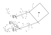
- FIG. 2 presents different forces impinging on the force system between support structure 14 and attached implement 10 .
- a cylinder force F Zyl is active between the two operative ends 28 , 30 of the lifting cylinder 26 .
- a force designated F K impinges on the articulation point K between the attached implement 10 and the lower link 18 , and is oriented at an angle ⁇ relative to the vehicle vertical line 32 .
- FIG. 3 Additional forces that impinge on the attached implement 10 are illustrated in FIG. 3 .
- a force impinging on the articulation point E and acting along the upper link 16 is designated F E .
- the weight force of the attached implement 10 at center of gravity S is marked m ⁇ g, where g is the gravitational constant.
- the lengths of paths AD and AK are known design parameters of the front powerlift 12 .
- the force F Zyl can be measured by means of a pressure sensor or differential pressure sensor in the lifting cylinder 26 .
- the force F E can be measured by means of pressure sensors and a length sensor on the upper link 16 , for example, or alternatively (in the case of a mechanical sensor 16 ) by means of a two-axial force sensor at the articulation point C.
- the angles ⁇ , ⁇ and ⁇ in equation (7) can be derived as follows:
- the x-coordinates A x , B x and the z-coordinates A z , B z are known since the articulation points A and B thereof on the support structure 14 have fixed coordinates relative to the coordinate system 33 .
- the x-coordinate C x and the z-coordinate C z of the articulation point C are also known, and are therefore either determined by sensors or specified by the operator.
- angles can also be measured by means of suitable angle sensors.
- biaxial force measuring pins can be used, as illustrated with reference to angle ⁇ and the two force components F Cx (along the x-axis of the coordinate system 33 ) and F Cz (along the z-axis of the coordinate system 33 ) in schematic form (see FIG. 3 ).
- variable x-coordinates and z-coordinates D x and D z of the link-connecting point D and E x and E z of the articulation point E can be derived mathematically, as described below.
- the first circle has a radius corresponding to the path BD with a circle center B and the second circle has a radius corresponding to the path AD with a circle center A.
- the path BD can be measured by means of a length sensor or a distance sensor, for example.
- the first circle has a radius corresponding to the path EK with a circle center K and the second circle has a radius corresponding to the path CE with a circle center C.
- the path CE can also be measured by means of a length sensor or a distance sensor on the upper link 16 , for example, or this path CE is known for a constant length of the upper link 16 .
- the path EK is a defined value corresponding to the dimensioning of the attached implement 10 .
- the x-coordinate S x of the center of gravity S relative to the coordinate system 33 can be determined by solving equation (4) for S x .
- the angle of inclination ⁇ is assumed to be 0°:
- the x-coordinate of the center of gravity S is determined as a function of
Landscapes
- Life Sciences & Earth Sciences (AREA)
- Engineering & Computer Science (AREA)
- Mechanical Engineering (AREA)
- Soil Sciences (AREA)
- Environmental Sciences (AREA)
- Zoology (AREA)
- Chemical & Material Sciences (AREA)
- Analytical Chemistry (AREA)
- Physics & Mathematics (AREA)
- General Physics & Mathematics (AREA)
- Vehicle Body Suspensions (AREA)
- Agricultural Machines (AREA)
Applications Claiming Priority (3)
| Application Number | Priority Date | Filing Date | Title |
|---|---|---|---|
| DE102016207204.8A DE102016207204A1 (de) | 2016-04-27 | 2016-04-27 | Verfahren zur Ermittlung einer Masse eines Anbaugerätes für ein Nutzfahrzeug |
| DE102016207204.8 | 2016-04-27 | ||
| DE102016207204 | 2016-04-27 |
Publications (2)
| Publication Number | Publication Date |
|---|---|
| US20170315005A1 US20170315005A1 (en) | 2017-11-02 |
| US10072996B2 true US10072996B2 (en) | 2018-09-11 |
Family
ID=58536843
Family Applications (1)
| Application Number | Title | Priority Date | Filing Date |
|---|---|---|---|
| US15/463,073 Active US10072996B2 (en) | 2016-04-27 | 2017-03-20 | Method for determining a mass of an attached implement for a utility vehicle |
Country Status (3)
| Country | Link |
|---|---|
| US (1) | US10072996B2 (de) |
| EP (1) | EP3238516B1 (de) |
| DE (1) | DE102016207204A1 (de) |
Families Citing this family (2)
| Publication number | Priority date | Publication date | Assignee | Title |
|---|---|---|---|---|
| DE102016224753A1 (de) | 2016-12-12 | 2018-06-14 | Deere & Company | Einrichtung zur Beeinflussung der Vertikaldynamik eines landwirtschaftlichen Fahrzeugs |
| JP7134860B2 (ja) * | 2018-12-26 | 2022-09-12 | 株式会社クボタ | 作業車両 |
Citations (13)
| Publication number | Priority date | Publication date | Assignee | Title |
|---|---|---|---|---|
| US3027029A (en) * | 1959-08-10 | 1962-03-27 | Ora W Clarke | Hydraulic shovel and loader |
| US3635364A (en) * | 1969-07-10 | 1972-01-18 | Gunnar Tingleff | Mobile working machine |
| US4627013A (en) * | 1982-12-01 | 1986-12-02 | Hitachi Construction Machinery Co., Ltd. | Load weight indicating system for load moving machine |
| US4825568A (en) * | 1987-08-12 | 1989-05-02 | Kubota Ltd. | Apparatus for controlling posture of work implement of loader |
| EP0892256A1 (de) | 1997-07-19 | 1999-01-20 | Robert Bosch Gmbh | Einrichtung zur Gewichtsbestimmung von angelenkten Lasten |
| US6518519B1 (en) * | 2000-08-30 | 2003-02-11 | Caterpillar Inc | Method and apparatus for determining a weight of a payload |
| US6699000B2 (en) * | 2000-05-10 | 2004-03-02 | J. C. Bamford Excavators Limited | Machine having a working arm |
| US20040200624A1 (en) * | 2002-04-11 | 2004-10-14 | Tomofumi Ochi | Working machine lifting device of tractor |
| US20080110647A1 (en) | 2006-10-26 | 2008-05-15 | Haibo Guo | Implement weight and center of gravity determination based on hitch cylinder pressure |
| US20100161185A1 (en) * | 2008-12-23 | 2010-06-24 | Caterpillar Inc. | Method and apparatus for calculating payload weight |
| EP2239467A2 (de) | 2009-04-06 | 2010-10-13 | Robert Bosch GmbH | Hydraulische Steueranordnung |
| EP2947431A1 (de) | 2014-05-21 | 2015-11-25 | Deere & Company | Verfahren zur bestimmung einer gewichtskraft einer nutzlast |
| US20150354177A1 (en) * | 2014-06-09 | 2015-12-10 | Caterpillar Inc. | Method and System for Estimating Payload Weight with Tilt Position Compensation |
-
2016
- 2016-04-27 DE DE102016207204.8A patent/DE102016207204A1/de not_active Withdrawn
-
2017
- 2017-03-20 US US15/463,073 patent/US10072996B2/en active Active
- 2017-04-11 EP EP17165908.9A patent/EP3238516B1/de active Active
Patent Citations (13)
| Publication number | Priority date | Publication date | Assignee | Title |
|---|---|---|---|---|
| US3027029A (en) * | 1959-08-10 | 1962-03-27 | Ora W Clarke | Hydraulic shovel and loader |
| US3635364A (en) * | 1969-07-10 | 1972-01-18 | Gunnar Tingleff | Mobile working machine |
| US4627013A (en) * | 1982-12-01 | 1986-12-02 | Hitachi Construction Machinery Co., Ltd. | Load weight indicating system for load moving machine |
| US4825568A (en) * | 1987-08-12 | 1989-05-02 | Kubota Ltd. | Apparatus for controlling posture of work implement of loader |
| EP0892256A1 (de) | 1997-07-19 | 1999-01-20 | Robert Bosch Gmbh | Einrichtung zur Gewichtsbestimmung von angelenkten Lasten |
| US6699000B2 (en) * | 2000-05-10 | 2004-03-02 | J. C. Bamford Excavators Limited | Machine having a working arm |
| US6518519B1 (en) * | 2000-08-30 | 2003-02-11 | Caterpillar Inc | Method and apparatus for determining a weight of a payload |
| US20040200624A1 (en) * | 2002-04-11 | 2004-10-14 | Tomofumi Ochi | Working machine lifting device of tractor |
| US20080110647A1 (en) | 2006-10-26 | 2008-05-15 | Haibo Guo | Implement weight and center of gravity determination based on hitch cylinder pressure |
| US20100161185A1 (en) * | 2008-12-23 | 2010-06-24 | Caterpillar Inc. | Method and apparatus for calculating payload weight |
| EP2239467A2 (de) | 2009-04-06 | 2010-10-13 | Robert Bosch GmbH | Hydraulische Steueranordnung |
| EP2947431A1 (de) | 2014-05-21 | 2015-11-25 | Deere & Company | Verfahren zur bestimmung einer gewichtskraft einer nutzlast |
| US20150354177A1 (en) * | 2014-06-09 | 2015-12-10 | Caterpillar Inc. | Method and System for Estimating Payload Weight with Tilt Position Compensation |
Non-Patent Citations (2)
| Title |
|---|
| European Search Report issued in counterpart application No. 17165908.9 dated Oct. 2, 2017. (7 pages). |
| German Search Report issued in counterpart application No. 102016207204.8 dated Dec. 16, 2016. (8 pages). |
Also Published As
| Publication number | Publication date |
|---|---|
| EP3238516A1 (de) | 2017-11-01 |
| DE102016207204A1 (de) | 2017-11-02 |
| EP3238516B1 (de) | 2020-10-14 |
| US20170315005A1 (en) | 2017-11-02 |
Similar Documents
| Publication | Publication Date | Title |
|---|---|---|
| US10684182B2 (en) | Method for determining a mass of an attached implement for a utility vehicle | |
| ES2377675T3 (es) | Vehículo agrícola y método para calcular la posición | |
| US11343956B2 (en) | System and method for monitoring soil conditions within a field | |
| EP2546627B1 (de) | Vorrichtung und Verfahren zur Bestimmung der Grösse und der Richtung einer Deichselkraft | |
| US11191204B2 (en) | System and method for monitoring soil conditions within a field | |
| US10524403B2 (en) | Method for determining a weight of a payload for a utility vehicle | |
| US9338937B2 (en) | Load sensing pin | |
| CN107787630A (zh) | 用于影响农用附加装置的位置的装置 | |
| US11788258B2 (en) | Systems and methods for determining a locational value of a load associated with an implement | |
| US10072996B2 (en) | Method for determining a mass of an attached implement for a utility vehicle | |
| US11533901B2 (en) | Traveling vehicle | |
| EP2946647B1 (de) | Verfahren zur kalibrierung einer kraftmesseinrichtung | |
| EP3391721B1 (de) | Landwirtschaftliches arbeitsfahrzeug und verfahren zur steuerung der anhängekupplung des landwirtschaftlichen arbeitsfahrzeugs | |
| Antoshchenkov et al. | MEASURING SYSTEM OF DYNAMICS AND ENERGY OF MOBILE MACHINES | |
| EP2947431B1 (de) | Verfahren zur bestimmung einer gewichtskraft einer nutzlast | |
| EP0625696B1 (de) | Verfahren und Vorrichtung zum Wiegen einer mit einem Zugfahrzeug verbundenen Last | |
| EP4296433A1 (de) | Verbesserte bestimmung eines baggerschwenkauslegerwinkels basierend auf einem winkelgeschwindigkeitsverhältnis | |
| US10098272B2 (en) | Method for calculating characteristic geometrical or control variables of a three point hitch | |
| US5270496A (en) | Tension bar | |
| Keen et al. | Force measurement between a tractor and a three point linkage mounted cultivation implement | |
| JP2505474Y2 (ja) | 荷役作業機の積載重量測定装置 | |
| EP2885959B1 (de) | Anbaugerätedetektionsanordnung für einen Traktor | |
| DE112020001099T5 (de) | Arbeitsmaschine und Verfahren zu deren Steuerung | |
| US20250107476A1 (en) | Systems and methods for an agricultural implement | |
| EP4599657A1 (de) | Identifizierung der flexion eines pflanzers |
Legal Events
| Date | Code | Title | Description |
|---|---|---|---|
| AS | Assignment |
Owner name: DEERE & COMPANY, ILLINOIS Free format text: ASSIGNMENT OF ASSIGNORS INTEREST;ASSIGNORS:MEID, MICHAEL;TRAUT, SEBASTIAN;JOHN DEERE GMBH & CO. KG;SIGNING DATES FROM 20141219 TO 20170316;REEL/FRAME:041645/0760 |
|
| STCF | Information on status: patent grant |
Free format text: PATENTED CASE |
|
| MAFP | Maintenance fee payment |
Free format text: PAYMENT OF MAINTENANCE FEE, 4TH YEAR, LARGE ENTITY (ORIGINAL EVENT CODE: M1551); ENTITY STATUS OF PATENT OWNER: LARGE ENTITY Year of fee payment: 4 |
|
| MAFP | Maintenance fee payment |
Free format text: PAYMENT OF MAINTENANCE FEE, 8TH YEAR, LARGE ENTITY (ORIGINAL EVENT CODE: M1552); ENTITY STATUS OF PATENT OWNER: LARGE ENTITY Year of fee payment: 8 |