US10071716B2 - Hydraulic system for a hydrodynamic machine - Google Patents
Hydraulic system for a hydrodynamic machine Download PDFInfo
- Publication number
- US10071716B2 US10071716B2 US15/083,959 US201615083959A US10071716B2 US 10071716 B2 US10071716 B2 US 10071716B2 US 201615083959 A US201615083959 A US 201615083959A US 10071716 B2 US10071716 B2 US 10071716B2
- Authority
- US
- United States
- Prior art keywords
- pump
- valve
- hydrodynamic machine
- working medium
- operational state
- Prior art date
- Legal status (The legal status is an assumption and is not a legal conclusion. Google has not performed a legal analysis and makes no representation as to the accuracy of the status listed.)
- Active, expires
Links
Images


Classifications
-
- B—PERFORMING OPERATIONS; TRANSPORTING
- B60—VEHICLES IN GENERAL
- B60T—VEHICLE BRAKE CONTROL SYSTEMS OR PARTS THEREOF; BRAKE CONTROL SYSTEMS OR PARTS THEREOF, IN GENERAL; ARRANGEMENT OF BRAKING ELEMENTS ON VEHICLES IN GENERAL; PORTABLE DEVICES FOR PREVENTING UNWANTED MOVEMENT OF VEHICLES; VEHICLE MODIFICATIONS TO FACILITATE COOLING OF BRAKES
- B60T10/00—Control or regulation for continuous braking making use of fluid or powdered medium, e.g. for use when descending a long slope
- B60T10/02—Control or regulation for continuous braking making use of fluid or powdered medium, e.g. for use when descending a long slope with hydrodynamic brake
-
- F—MECHANICAL ENGINEERING; LIGHTING; HEATING; WEAPONS; BLASTING
- F16—ENGINEERING ELEMENTS AND UNITS; GENERAL MEASURES FOR PRODUCING AND MAINTAINING EFFECTIVE FUNCTIONING OF MACHINES OR INSTALLATIONS; THERMAL INSULATION IN GENERAL
- F16D—COUPLINGS FOR TRANSMITTING ROTATION; CLUTCHES; BRAKES
- F16D57/00—Liquid-resistance brakes; Brakes using the internal friction of fluids or fluid-like media, e.g. powders
- F16D57/02—Liquid-resistance brakes; Brakes using the internal friction of fluids or fluid-like media, e.g. powders with blades or like members braked by the fluid
-
- F—MECHANICAL ENGINEERING; LIGHTING; HEATING; WEAPONS; BLASTING
- F16—ENGINEERING ELEMENTS AND UNITS; GENERAL MEASURES FOR PRODUCING AND MAINTAINING EFFECTIVE FUNCTIONING OF MACHINES OR INSTALLATIONS; THERMAL INSULATION IN GENERAL
- F16D—COUPLINGS FOR TRANSMITTING ROTATION; CLUTCHES; BRAKES
- F16D57/00—Liquid-resistance brakes; Brakes using the internal friction of fluids or fluid-like media, e.g. powders
- F16D57/04—Liquid-resistance brakes; Brakes using the internal friction of fluids or fluid-like media, e.g. powders with blades causing a directed flow, e.g. Föttinger type
-
- F—MECHANICAL ENGINEERING; LIGHTING; HEATING; WEAPONS; BLASTING
- F16—ENGINEERING ELEMENTS AND UNITS; GENERAL MEASURES FOR PRODUCING AND MAINTAINING EFFECTIVE FUNCTIONING OF MACHINES OR INSTALLATIONS; THERMAL INSULATION IN GENERAL
- F16H—GEARING
- F16H41/00—Rotary fluid gearing of the hydrokinetic type
- F16H41/24—Details
- F16H41/30—Details relating to venting, lubrication, cooling, circulation of the cooling medium
Definitions
- the invention relates to a hydrodynamic machine, in particular a hydrodynamic retarder to produce a braking torque by way of a fluid.
- Hydrodynamic machines or hydrodynamic retarders generally include a housing in which a first bladed wheel, in particular a rotor and a second bladed wheel, in particular a stator arranged concentrically thereto which together form a toroidal chamber, and that are grouped about a common axis of rotation are arranged.
- Retarders or hydrodynamic brakes can be arranged in a drive train on the motor side or respectively gear box side.
- the fill level of the retarder with a working fluid determines the rotor “braking torque”.
- oil for example is pumped into the working chamber.
- the driven rotor accelerates this oil and transfers it on the outside diameter of the working chamber to the stator.
- the oil is slowed and returned via the inside diameter of the working chamber back into the rotor. Due to the generally known interaction between rotor and stator the braking torque develops.
- a hydraulic system ensures that in the non-braking operation and/or in the braking operation the working chamber is supplied or respectively filled with the appropriate working medium. It is thereby of special consideration that the heat that is generated in both operational modes is removed from the working chamber by way of the working medium and is returned for cooling to a cooling circuit in a cooler. It is particularly necessary in the non-braking operation that a minimum volume is routed through the working chamber in order to cool the retarder also in the non-braking operation.
- the working chamber is connected to a working fluid circuit via the fluid supply and the fluid discharge, wherein said circuit consists essentially of a working fluid accumulator, a cooler, a pump and several valves.
- An open loop and closed loop control unit is connected with the components of a hydraulic system in such a manner that the braking torque and/or working medium flow can be controlled or respectively regulated.
- a hydraulic system of this type is known for example from DE 10 2006 030 791 A1.
- the objective is essentially to direct the working medium in all operational modes through a cooler in order to achieve optimum temperature control.
- the working medium is an oil that at the same time is used for gear lubrication.
- the invention includes a hydrodynamic machine or a retarder, in particular a hydrodynamic retarder, comprising a first bladed wheel, in particular a rotor and a second bladed wheel arranged concentrically thereto, in particular a stator that together form a toroidal working chamber.
- the hydrodynamic machine moreover includes an electrohydraulic system including an open loop and closed loop control unit, a pump, a heat exchanger, a working medium accumulator, a valve and a line system, wherein a volume flow circulation of the working medium can be generated by the pump through the line system and the working chamber.
- the electrohydraulic system is characterized in that the valve is a pressure control valve by means of which the braking performance or respectively the braking torque can be controlled/adjusted.
- the system pressure can be advantageously controlled proportionally to the torque or respectively braking torque.
- the pressure control valve may be a 3/3 directional valve or a 3/2 directional valve.
- the electrohydraulic system for control/adjustment of the pressure control valve can moreover include a pressure differential control.
- the pressure differential control comprises at least one proportional valve and the open loop and closed loop control unit.
- a sensor can be coupled for torque measurement with the open loop and closed loop control unit so that torque measurement values can also be used for the pressure differential control.
- the pump is moreover integrated into the hydraulic system in such a manner that the pump can be switched in two operational states: a first operational state, the non-braking state; and a second operational state, the braking state; wherein the line system is designed in such a manner that a volume flow circulation can be pumped through the working chamber in both operational states.
- the pump can be a Gerotor pump that is coupled or non-rotatably connected with the rotor.
- the switching valve for switching of the operational state can moreover be located at the pressure side of the pump, wherein a bypass line is provided for bypassing the switching valve and the pump, back into the working medium accumulator is provided.
- a bypass line is provided for bypassing the switching valve and the pump, back into the working medium accumulator is provided.
- the substantial control of the working medium volume occurs on the pressure side of the pump, in particular through the downstream hydraulic- or line system.
- Non-essential working medium is returned into the working medium accumulator before and/or after the valve.
- the switching valve for switching of the operational state can be arranged on the suction side of the pump, whereby in this arrangement a bypass line is provided to bypass the valve and through which the working medium can be sucked by the pump.
- a second bypass line is provided, so that working medium or a partial volume flow can be pumped in the first operating state, the non-braking operation, into the working chamber also in this embodiment.
- a working medium filter can be provided in this bypass line.
- a proportional valve by way of which the first pressure control valve is controlled/adjusted can moreover be coupled advantageously after the working medium filter with the bypass line.
- the proportional valve is moreover kept ready for operation at all times due to the coupling with the bypass line, since there is always a certain working medium pressure present.
- FIG. 1 illustrates a sectional view of a retarder according to the invention
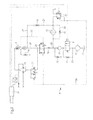
- FIG. 2 illustrates a first embodiment for the design of a hydraulic system
- FIG. 3 illustrates a second embodiment for the design of a hydraulic system.
- FIG. 1 is a sectional view of an exemplary retarder that is used in particular in buses and commercial vehicles.
- the retarder includes a housing consisting of several housing parts, a rotor 1 and a stator 2 that together form a toroidal annulus or working chamber 4 .
- the retarder is driven by a working medium, in particular an oil that is pumped by way of pump 11 via a line system into intake channel 6 or respectively spiral channel. From intake channel 6 the oil arrives through separating gap 3 into working chamber 4 . During the braking operation, a circulatory flow forms in working chamber 4 . Driven rotor 1 accelerates the oil and transfers it at the outside diameter into stator 2 . There, the oil impacts on the stationary stator blades and is slowed down. On the inside diameter the oil flows again to rotor 2 . The resulting braking energy is converted predominantly into heat, so that it is necessary to cool part of the oil permanently by way of a heat exchanger 19 . This part of the oil is drained from the circulatory flow through the fluid outlet or outlet channel 7 .
- a working medium in particular an oil that is pumped by way of pump 11 via a line system into intake channel 6 or respectively spiral channel. From intake channel 6 the oil arrives through separating gap 3 into working chamber 4 .
- a circulatory flow forms in working chamber 4
- the drained oil is then pumped through a heat exchanger 19 and subsequently—depending on the operational condition—back into working chamber 4 , so that a circulatory flow is created. In non-braking operation the oil is pumped back into working medium accumulator 10 .
- FIG. 2 illustrates a first embodiment for the design of the hydraulic system.
- a substantial characteristic of this design is the positioning of pump 11 before valve 9 .
- the valve is herein illustrated in the non-braking operational position.
- a throttle 14 is installed in bypass line 27 that can be adjusted in such a manner that a small part of the working medium is pumped into working chamber 4 .
- the volume flow is to be selected large enough that sufficient heat removal out of the working chamber is ensured. Moreover, it may not be so large as to create an increased no-load resistance.
- From working chamber 4 the oil is pumped through heat exchanger 19 back into working medium accumulator 10 . Thus, a small amount of oil is continuously being cooled in the non-braking operation by way of heat exchanger 19 .
- Second bypass line 28 feeds the remaining, substantially larger volume flow directly back into working medium accumulator 10 .
- Pump 11 thus runs virtually in a no-load mode as a result of which the losses in the non-braking operation can be minimized without having to adjust the pump 11 .
- a Gerotor pump can hereby be used that is driven directly by the rotor shaft.
- valve 9 , 16 and 20 are switched. As soon as switching valve 9 that is located on the pressure side of pump 11 switches, the working medium gets into working chamber 4 via working medium limes 30 , 31 and valve 16 .
- Valve 16 is a pressure compensator that is switched into the appropriate switching position via the pressure measured in working chamber 4 and the pressure predefined by proportional valve 21 .
- a pressure compensator is a differential pressure valve or a pressure control valve that can regulate a differential pressure between an externally fed measuring location and an actual pressure at the valve.
- Valve 16 can be designed as a 3/3 directional valve as illustrated herein, or also as a 2/3 directional valve.
- the system pressure in working chamber 4 can be regulated proportionally to the desired braking torque at the rotor shaft by way of the pressure compensator.
- a torque sensor can be provided for this purpose, for example on the rotor shaft.
- proportional valve 21 is supplied with system pressure only when switching into the braking position.
- a filter 13 is provided for the protection of proportional valve 21 that filters the entire working medium necessary for the braking operation.
- FIG. 3 illustrates a second embodiment of the structure of the hydraulic system. This differs substantially from the first embodiment, wherein also in this embodiment in the non-braking operation, a certain volume of working medium is pumped into working chamber 4 by way of pump 11 .
- valve 9 is located on the suction side of pump 11 .
- bypass line 26 that is throttled by way of a suction throttle 17 from working medium accumulator 10 , and is pumped via bypass 27 into working chamber 4 .
- Bypass line 27 thereby ends in inlet channel 6 in such a way that the working medium is essentially pumped through working chamber 4 into outlet channel 7 .
- An additional throttle 14 is installed in bypass 27 , and before the same, a proportional valve 21 is connected with valve 25 to bypass line 27 for control of the pressure compensator. In this way it is ensured that there is always sufficient system pressure available at proportional valve 21 , and that therefore always a quick delay-free adjustment of the braking effect is facilitated.
- a filter 13 in particular a fine filter is installed in bypass line 27 before proportional valve 21 . As a result, only the relatively small volume that is necessary for the non-braking operation and for control of proportional valve 21 is filtered.
- Valve 25 is a pressure compensator that is switched into the appropriate switching position according to the pressure that is measured in working chamber 4 and the pressure that is predefined by proportional valve 21 .
- Valve 25 can be designed as a 2/3 directional valve as indicated in this example, or alternatively as a 3/3 directional valve.
- the pressure compensator the system pressure in working chamber 4 can be adjusted proportionally to the desired braking torque at the rotor shaft.
- a torque sensor may for example by provided on the rotor shaft.
- a Gerotor pump 11 is provided as the pump and is connected non-rotatably with the rotor shaft. Both embodiments ensure that the pump resistance in the non-braking operation is very low and supports the braking action in the braking operation.
- the filters and return lines into the working medium accumulator 10 illustrated in the drawings, and the throttles or check valves that are installed in the lines, are indeed necessary for the overall function but are routinely used by the expert.
Landscapes
- Engineering & Computer Science (AREA)
- General Engineering & Computer Science (AREA)
- Mechanical Engineering (AREA)
- Physics & Mathematics (AREA)
- Fluid Mechanics (AREA)
- Transportation (AREA)
- Braking Arrangements (AREA)
- Transmission Of Braking Force In Braking Systems (AREA)
Applications Claiming Priority (4)
| Application Number | Priority Date | Filing Date | Title |
|---|---|---|---|
| DE201310219792 DE102013219792A1 (de) | 2013-09-30 | 2013-09-30 | Hydrauliksystem für eine hydrodynamische Maschine |
| DE102013219792.6 | 2013-09-30 | ||
| DE102013219792 | 2013-09-30 | ||
| PCT/EP2014/070590 WO2015044328A2 (de) | 2013-09-30 | 2014-09-26 | Hydrauliksystem für eine hydrodynamische maschine |
Related Parent Applications (1)
| Application Number | Title | Priority Date | Filing Date |
|---|---|---|---|
| PCT/EP2014/070590 Continuation WO2015044328A2 (de) | 2013-09-30 | 2014-09-26 | Hydrauliksystem für eine hydrodynamische maschine |
Publications (2)
| Publication Number | Publication Date |
|---|---|
| US20160244041A1 US20160244041A1 (en) | 2016-08-25 |
| US10071716B2 true US10071716B2 (en) | 2018-09-11 |
Family
ID=51703134
Family Applications (1)
| Application Number | Title | Priority Date | Filing Date |
|---|---|---|---|
| US15/083,959 Active 2035-05-24 US10071716B2 (en) | 2013-09-30 | 2016-03-29 | Hydraulic system for a hydrodynamic machine |
Country Status (4)
| Country | Link |
|---|---|
| US (1) | US10071716B2 (de) |
| EP (1) | EP3052350B1 (de) |
| DE (1) | DE102013219792A1 (de) |
| WO (1) | WO2015044328A2 (de) |
Cited By (1)
| Publication number | Priority date | Publication date | Assignee | Title |
|---|---|---|---|---|
| US11312341B2 (en) | 2017-04-26 | 2022-04-26 | Dana Belgium N.V. | Hydrodynamic retarder system and method of controlling a hydrodynamic retarder system |
Families Citing this family (1)
| Publication number | Priority date | Publication date | Assignee | Title |
|---|---|---|---|---|
| DE102015218358A1 (de) | 2015-09-24 | 2017-03-30 | Voith Patent Gmbh | Ölversorgung eines Automatgetriebes oder automatisierten Schaltgetriebes, in einem Antriebsstrang |
Citations (7)
| Publication number | Priority date | Publication date | Assignee | Title |
|---|---|---|---|---|
| US2496497A (en) * | 1946-08-16 | 1950-02-07 | Robert C Russell | Brake |
| DE2757237A1 (de) | 1977-12-22 | 1979-06-28 | Zahnradfabrik Friedrichshafen | Hydrodynamische dauerbremsanlage |
| DE19909690A1 (de) | 1999-03-05 | 2000-09-21 | Voith Turbo Kg | Verfahren zur Steuerung einer hydrodynamischen Baueinheit und Steuervorrichtung |
| US6817455B1 (en) * | 1999-10-27 | 2004-11-16 | Zf Friedrichshafen Ag | Retarder system |
| DE102006030791A1 (de) | 2006-06-30 | 2008-01-03 | Zf Friedrichshafen Ag | Hydrodynamischer Retarder |
| CN101448690A (zh) | 2006-05-23 | 2009-06-03 | Zf腓德烈斯哈芬股份公司 | 用于调节和控制汽车液力减速器的方法和装置 |
| CN103101522A (zh) | 2013-01-30 | 2013-05-15 | 厦门宇龙机械有限公司 | 一种应用于非驱动车桥的辅助制动装置 |
-
2013
- 2013-09-30 DE DE201310219792 patent/DE102013219792A1/de not_active Withdrawn
-
2014
- 2014-09-26 EP EP14784011.0A patent/EP3052350B1/de active Active
- 2014-09-26 WO PCT/EP2014/070590 patent/WO2015044328A2/de not_active Ceased
-
2016
- 2016-03-29 US US15/083,959 patent/US10071716B2/en active Active
Patent Citations (7)
| Publication number | Priority date | Publication date | Assignee | Title |
|---|---|---|---|---|
| US2496497A (en) * | 1946-08-16 | 1950-02-07 | Robert C Russell | Brake |
| DE2757237A1 (de) | 1977-12-22 | 1979-06-28 | Zahnradfabrik Friedrichshafen | Hydrodynamische dauerbremsanlage |
| DE19909690A1 (de) | 1999-03-05 | 2000-09-21 | Voith Turbo Kg | Verfahren zur Steuerung einer hydrodynamischen Baueinheit und Steuervorrichtung |
| US6817455B1 (en) * | 1999-10-27 | 2004-11-16 | Zf Friedrichshafen Ag | Retarder system |
| CN101448690A (zh) | 2006-05-23 | 2009-06-03 | Zf腓德烈斯哈芬股份公司 | 用于调节和控制汽车液力减速器的方法和装置 |
| DE102006030791A1 (de) | 2006-06-30 | 2008-01-03 | Zf Friedrichshafen Ag | Hydrodynamischer Retarder |
| CN103101522A (zh) | 2013-01-30 | 2013-05-15 | 厦门宇龙机械有限公司 | 一种应用于非驱动车桥的辅助制动装置 |
Non-Patent Citations (2)
| Title |
|---|
| Chinese Office Action dated May 26, 2017 for Chinese Application No. 201480053992.2 (8 pages). |
| Notice of Transfer of International Research Report and the Written Notice Issued for International Searching Authority or Statement dated Mar. 31, 2015 for International Application No. PCT/EP2014/070590 (9 pages). |
Cited By (1)
| Publication number | Priority date | Publication date | Assignee | Title |
|---|---|---|---|---|
| US11312341B2 (en) | 2017-04-26 | 2022-04-26 | Dana Belgium N.V. | Hydrodynamic retarder system and method of controlling a hydrodynamic retarder system |
Also Published As
| Publication number | Publication date |
|---|---|
| WO2015044328A3 (de) | 2015-05-21 |
| EP3052350B1 (de) | 2020-07-08 |
| EP3052350A2 (de) | 2016-08-10 |
| WO2015044328A2 (de) | 2015-04-02 |
| DE102013219792A1 (de) | 2015-04-02 |
| US20160244041A1 (en) | 2016-08-25 |
| CN105593081A (zh) | 2016-05-18 |
Similar Documents
| Publication | Publication Date | Title |
|---|---|---|
| US10570972B2 (en) | Hydraulic system for a hydrodynamic machine | |
| CN105555625B (zh) | 液力减速装置以及将液力减速装置与车辆一起使用的方法 | |
| CN102792027B (zh) | 螺杆式压缩机 | |
| JP3760275B2 (ja) | 液圧駆動アセンブリ | |
| CN105546077B (zh) | 静液压制动方案 | |
| EP3225450B1 (de) | Kühlsystem für eine mit einem automatikgetriebe mit hydraulischem retarder gekoppelte brennkraftmaschine | |
| CN105202163B (zh) | 一种风电齿轮箱润滑冷却系统及风力发电机组 | |
| CN105939909B (zh) | 液力减速装置及其使用方法和车辆 | |
| US9650023B2 (en) | Cooling circuit for a motor vehicle having a hydrodynamic retarder | |
| US8176734B2 (en) | Hydrostatic transmission having proportional pressure variable displacement pump for loop charge and fan flow supply | |
| JPH03213455A (ja) | 流体静力学的ブレーキ負荷変換器 | |
| JP2018510308A (ja) | ドレン弁 | |
| US20160244041A1 (en) | Hydraulic system for a hydrodynamic machine | |
| CN108730380A (zh) | 用于水减速器的冷却系统 | |
| CN104029664B (zh) | 一种带闭锁装置及控制油路的可消除鼓风损失的液力缓速器 | |
| CN108397428B (zh) | 预紧模块和次级调校的液压系统 | |
| KR20150097749A (ko) | 차량의 냉각 시스템 | |
| EP2559878A1 (de) | Kühlsystem, insbesondere eines Kraftfahrzeuges | |
| JP2009541127A (ja) | 流体リターダ | |
| CN107709722A (zh) | 液力缓速器装置 | |
| SE1351227A2 (sv) | Förbränningsmotor samt kåpsammansättning därför | |
| US20050016804A1 (en) | Hydrodynamic braking system provide with a retarder | |
| CN104508330A (zh) | 变速箱液压回路 | |
| CN105593081B (zh) | 用于液力机械的液压系统 | |
| WO2015044330A1 (de) | Hydrauliksystem für eine hydrodynamische maschine |
Legal Events
| Date | Code | Title | Description |
|---|---|---|---|
| AS | Assignment |
Owner name: VOITH PATENT GMBH, GERMANY Free format text: ASSIGNMENT OF ASSIGNORS INTEREST;ASSIGNORS:SCHLOSSER, MARKUS;ROMMEL, MATTHIAS;OTT, HELMUT;AND OTHERS;REEL/FRAME:038520/0531 Effective date: 20160429 |
|
| STCF | Information on status: patent grant |
Free format text: PATENTED CASE |
|
| MAFP | Maintenance fee payment |
Free format text: PAYMENT OF MAINTENANCE FEE, 4TH YEAR, LARGE ENTITY (ORIGINAL EVENT CODE: M1551); ENTITY STATUS OF PATENT OWNER: LARGE ENTITY Year of fee payment: 4 |
|
| FEPP | Fee payment procedure |
Free format text: MAINTENANCE FEE REMINDER MAILED (ORIGINAL EVENT CODE: REM.); ENTITY STATUS OF PATENT OWNER: LARGE ENTITY |